
お問い合わせ
ダウンロード
マニュアル、データシート、ソフトウェアなどのダウンロード:
フィードバック
CAN通信バスの仕組みとトラブルシューティング
CAN通信とは?
コントローラ・エリア・ネットワーク(CAN)通信とは、元々は車載アプリケーション用に設計されたバス通信の規格ですが、他の領域にも対応しています。CAN通信バスは、用途に応じてさまざまなタイプのケーブルで動作する平衡(差動)2線式インタフェースです。規格ではいくつかの異なるデータ転送速度が定義されていますが、CANで最も高速なのは1 Mbpsです。最新版のCAN FD(フレキシブル・データ・レート)では、伝送速度が10 Mbpsまで向上し、パッケージのペイロード・データ・フィールドの最大長さも増加しています。信号品質を維持するためには、ケーブルの各端の終端抵抗を120 Ωにしてインピーダンスのマッチングを確保する必要があります。
CAN通信バスは、1980年代の導入以来、電子制御ユニット(ECU)間のデータ転送や車両センサを使用したデータ転送に使用されています。
コネクテッド・カーとCAN通信バス
近年、自動車において生成、転送、および受信されるデータの量は大幅に増加しており、今後も増加し続けると思われます。現在、多くの自動車に80を超える電子制御ユニット(ECU)が搭載され、さまざまなバス・ネットワークを経由して接続されています。一部の高級車ではすでに150を超えるECUが使用されているため、この数は今後数年間で100を超えることが予想されます。
車両サブシステム間の高度な統合により、センサ信号とアクチュエータ信号の処理に加えて、一度に複数のシリアル・バスを介して多くのECUが通信できます。例えば、ECUがCAN(クリティカル・システムの場合)とLIN(ウィンドウやミラーなどの優先度の低い制御の場合)の両方で通信することは非常に一般的です。
CAN通信バスのトラブルシューティング
運転手の安全はこれらのシステムの正常な通信に依存しているため、CAN通信バスを正しく構成することが非常に重要です。幸いなことに、ミックスド・シグナル・オシロスコープなどの適切なCAN通信バス・デコード・ツールがあれば、CAN通信バスのデコードとCAN通信バス問題のトラブルシューティングは簡単に実行できます。この短編ガイドでは、トラブルシューティングのヒントや、作業を迅速に完了させるのに必要な機器をご紹介します。
オシロスコープによるCAN通信バスのデコードとトラブルシューティング
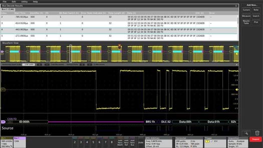
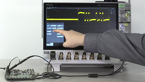
チャンネル1のCAN FD信号がデコードされ、バス波形(下)およびイベント・テーブル(上)として表示されています。
CAN通信バス・プロトコルのデコード
シリアル・バス・プロトコルを手動でデコードすることは時間がかかり、間違いも起こりやすくなります。テクトロニクスの車載バスのデコード/トリガ・パッケージは、CAN、CAN FD、LIN、FlexRayなど一般的なECUバスに対して、自動化された簡単なデコードおよびトリガ機能を備えています。
オシロスコープによるCAN通信バスのトラブルシューティング
CAN通信バス・プロトコルのデコードだけで十分ではありません。バスが動作しない、さらにはバスの動作が断続的になった場合のトラブルシューティングは、バス・トラフィックの範疇を超えてシグナル・インテグリティの領域に関係してきます。
クロストーク、ノイズ、不適切な終端などの物理層のシグナル・インテグリティの事柄から発生するこれらの問題は、波形解析によって最も効果的に検出できます。
オシロスコープにより、エンジニアはアナログ・バスの波形を検査して信号品質とノイズを評価し、複数の信号を調査して相互作用を検出し、クロストークを特定することができます。
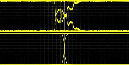
CAN通信バスには120Ω終端が必要です。終端されていないバスは、信号品質が悪くなります(上位信号)。
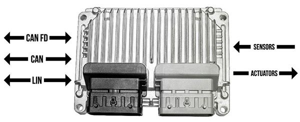
ECUは、CAN、LIN、他のバスを介して、センサおよびアクチュエータと直接通信します。
オシロスコープによるECUの可視化
マルチバス、マルチセンサ/アクチュエータ・システムは複雑であるため、作業環境の概要を理解することは困難な場合があります。
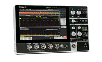
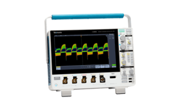
ほとんどのテクトロニクスのオシロスコープは、複数のバスと制御信号を同時に表示することができます。ミックスド・シグナル・オシロスコープは、バス・デコードにデジタル・チャネルを使用することができ、アナログ・チャネルを信号品質の評価に解放します。 5シリーズMSOは、チャンネル数の多いFlexChannel入力と大型HDディスプレイにより、複雑なECUの可視化に威力を発揮します。
CAN通信バスの関連資料

CAN通信バスに関するよくある質問
CAN通信バスの終端抵抗とは?
CAN通信バスのデメリットは?
CAN通信バス・デコーダとは?
CAN通信バス・デコーダは、コントローラ・エリア・ネットワーク(CAN)バスを介して送信された信号を解釈するデバイスです。そのデバイスとして、オシロスコープが挙げられます。
CAN通信ネットワークは、最新の自動車や複雑なシステムに採用されています。デコーダは、CAN通信バスを介して転送された速度、回転数、温度、その他のデータなどの情報を抽出します。
CAN通信バス・デコーダを使う利点は?
CAN通信バス・デコーダは、CAN通信バスを介して転送された重要データにリアルタイムでアクセスできるため、診断、性能の調整、データ解析などの幅広い目的に使用されています。また、自動車のシステムや部品の問題検出や診断にも役立つため、より迅速かつ高確度のトラブルシューティングが可能になります。
CAN通信バス・デコーダの動作原理は?
CAN通信バス・デコーダは、CAN通信バスを介して転送された信号を解釈し、専用のソフトウェアによりデータ・パケットをデコードすることで機能します。デコーダには使いやすい形式でデータが表示されるため、簡単に解釈と解析を実施できます。
CAN通信バス・デコーダでデコードできるデータの種類は?
CAN通信バス・デコーダは、エンジン回転数、スロットル位置、車速、クーラント温度、燃料レベルなど、CAN通信バスを介して転送された様々なデータを抽出します。デコードできる特定のデータは、車両のメーカ、モデル、使用するCAN通信バス・デコーダのタイプによって異なります。
CAN通信バス・デコーダはどの車両にも使用できる?
CAN通信バス・デコーダは、コントローラ・エリア・ネットワーク(CAN)バスを使用するほぼすべての最新型車両で利用できます。ただし、車両のメーカ、モデル、使用するCAN通信バス・デコーダのタイプに応じて互換性が異なります。CAN通信バス・デコーダを購入する前に、メーカ仕様を確認することが常に最善の方法です。
CAN通信バス・デコーダにはさまざまなタイプがある?
はい。シンプルなハンドヘルド・デバイスから高度なソフトウェアベースのシステムまで、複数のCAN通信バス・デコーダが市販されています。最適なデコーダのタイプは、固有のニーズや、CAN通信バスから抽出する必要があるデータの複雑性によって異なります。
CAN通信バス・デコーダは車両性能の改善に役立つ?
はい。CAN通信バス・デコーダは車両性能データの監視と解析に利用できるため、車両性能の改善や、最適化するべき領域の特定に役立ちます。たとえば、燃料や点火のタイミングを調整してエンジン性能を微調整する場合や、抵抗が発生して燃料消費量が増加している車両領域を特定する場合に役立ちます。
CAN通信バス・デコーダの設定方法は?
CAN通信バス・デコーダの設定は簡単にできます。テクトロニクスのオシロスコープを例にしたCANバス・デコーダの設定手順をご参考にご覧ください。