お問い合わせ
ダウンロード
マニュアル、データシート、ソフトウェアなどのダウンロード:
フィードバック
4 Series MSO Service Manual
This manual provides the theory of operation, service instructions and a list of replaceable parts for the MSO44 and MSO46 instruments.
該当製品:
MSO44, MSO46
By downloading, you agree to the terms and conditions of the Manuals Download Agreement.
Manuals Download Agreement
ATTENTION: please read the following terms and conditions carefully before downloading any documents from this website. By downloading manuals from Tektronix' website, you agree to the following terms and conditions:
Manuals for Products That Are Currently Supported:
Tektronix hereby grants permission and license to owners of Tektronix instruments to download and reproduce the manuals on this website for their own internal or personal use. Manuals for currently supported products may not be reproduced for distribution to others unless specifically authorized in writing by Tektronix, Inc.
A Tektronix manual may have been revised to reflect changes made to the product during its manufacturing life. Thus, different versions of a manual may exist for any given product. Care should be taken to ensure that one obtains the proper manual version for a specific product serial number.
Manuals for Products That Are No Longer Supported:
Tektronix cannot provide manuals for measurement products that are no longer eligible for long term support. Tektronix hereby grants permission and license for others to reproduce and distribute copies of any Tektronix measurement product manual, including user manuals, operator's manuals, service manuals, and the like, that (a) have a Tektronix Part Number and (b) are for a measurement product that is no longer supported by Tektronix.
A Tektronix manual may be revised to reflect changes made to the product during its manufacturing life. Thus, different versions of a manual may exist for any given product. Care should be taken to ensure that one obtains the proper manual version for a specific product serial number.
This permission and license does not apply to any manual or other publication that is still available from Tektronix, or to any manual or other publication for a video production product or a color printer product.
Disclaimer:
Tektronix does not warrant the accuracy or completeness of the information, text, graphics, schematics, parts lists, or other material contained within any measurement product manual or other publication that is not supplied by Tektronix or that is produced or distributed in accordance with the permission and license set forth above.
Tektronix may make changes to the content of this website or to its products at any time without notice.
Limitation of Liability:
TEKTRONIX SHALL NOT BE LIABLE FOR ANY DAMAGES WHATSOEVER (INCLUDING, WITHOUT LIMITATION, ANY CONSEQUENTIAL OR INCIDENTAL DAMAGES, DAMAGES FOR LOSS OF PROFITS, BUSINESS INTERRUPTION, OR FOR INFRINGEMENT OF INTELLECTUAL PROPERTY) ARISING OUT OF THE USE OF ANY MEASUREMENT PRODUCT MANUAL OR OTHER PUBLICATION PRODUCED OR DISTRIBUTED IN ACCORDANCE WITH THE PERMISSION AND LICENSE SET FORTH ABOVE.
Read Online
MAINTENANCE
- Preventing ESD
- Adjustment procedures
- Inspection and cleaning
- Exterior cleaning (other than display)
- Flat panel display cleaning
- Interior cleaning
- Lubrication
- Returning instrument for service
- Removal and replacement procedures
- Required equipment
- Remove the front-panel knobs
- Remove instrument feet
- Remove the handle
- Remove the rear grill and case
- Remove the rear chassis assembly
- Remove the power supply bracket
- Remove the power supply
- Remove the main fan assembly
- Remove the main board
- Remove the processor board
- Troubleshooting
Important safety information
This manual contains information and warnings that must be followed by the user for safe operation and to keep the product in a safe condition.
To safely perform service on this product, see the Service safety summary that follows the General safety summary.
General safety summary
Use the product only as specified. Review the following safety precautions to avoid injury and prevent damage to this product or any products connected to it. Carefully read all instructions. Retain these instructions for future reference.
This product shall be used in accordance with local and national codes.
For correct and safe operation of the product, it is essential that you follow generally accepted safety procedures in addition to the safety precautions specified in this manual.
The product is designed to be used by trained personnel only.
Only qualified personnel who are aware of the hazards involved should remove the cover for repair, maintenance, or adjustment.
Before use, always check the product with a known source to be sure it is operating correctly.
This product is not intended for detection of hazardous voltages.
Use personal protective equipment to prevent shock and arc blast injury where hazardous live conductors are exposed.
While using this product, you may need to access other parts of a larger system. Read the safety sections of the other component manuals for warnings and cautions related to operating the system.
When incorporating this equipment into a system, the safety of that system is the responsibility of the assembler of the system.
To avoid fire or personal injury
Use proper power cord
Use only the power cord specified for this product and certified for the country of use. Do not use the provided power cord for other products.
Ground the product
This product is grounded through the grounding conductor of the power cord. To avoid electric shock, the grounding conductor must be connected to earth ground. Before making connections to the input or output terminals of the product, ensure that the product is properly grounded. Do not disable the power cord grounding connection.
Power disconnect
The power cord disconnects the product from the power source. See instructions for the location. Do not position the equipment so that it is difficult to operate the power cord; it must remain accessible to the user at all times to allow for quick disconnection if needed.
Connect and disconnect properly
Do not connect or disconnect probes or test leads while they are connected to a voltage source.
Use only insulated voltage probes, test leads, and adapters supplied with the product, or indicated by Tektronix to be suitable for the product.
Observe all terminal ratings
To avoid fire or shock hazard, observe all rating and markings on the product. Consult the product manual for further ratings information before making connections to the product.
Do not exceed the Measurement Category (CAT) rating and voltage or current rating of the lowest rated individual component of a product, probe, or accessory. Use caution when using 1:1 test leads because the probe tip voltage is directly transmitted to the product.
Do not apply a potential to any terminal, including the common terminal, that exceeds the maximum rating of that terminal.
Do not float the common terminal above the rated voltage for that terminal.
The measurement terminals on this product are not rated for connection to Category III or IV circuits.
Do not operate without covers
Do not operate this product with covers or panels removed, or with the case open. Hazardous voltage exposure is possible.
Avoid exposed circuitry
Do not touch exposed connections and components when power is present.
Do not operate with suspected failures
If you suspect that there is damage to this product, have it inspected by qualified service personnel.
Disable the product if it is damaged. Do not use the product if it is damaged or operates incorrectly. If in doubt about safety of the product, turn it off and disconnect the power cord. Clearly mark the product to prevent its further operation.
Before use, inspect voltage probes, test leads, and accessories for mechanical damage and replace when damaged. Do not use probes or test leads if they are damaged, if there is exposed metal, or if a wear indicator shows.
Examine the exterior of the product before you use it. Look for cracks or missing pieces.
Use only specified replacement parts.
Do not operate in wet/damp conditions
Be aware that condensation may occur if a unit is moved from a cold to a warm environment.
Do not operate in an explosive atmosphere
Keep product surfaces clean and dry
Remove the input signals before you clean the product.
Provide proper ventilation
Refer to the installation instructions in the manual for details on installing the product so it has proper ventilation.
Slots and openings are provided for ventilation and should never be covered or otherwise obstructed. Do not push objects into any of the openings.
Provide a safe working environment
Always place the product in a location convenient for viewing the display and indicators.
Avoid improper or prolonged use of keyboards, pointers, and button pads. Improper or prolonged keyboard or pointer use may result in serious injury.
Be sure your work area meets applicable ergonomic standards. Consult with an ergonomics professional to avoid stress injuries.
Use care when lifting and carrying the product. This product is provided with a handle or handles for lifting and carrying.
Use only the Tektronix rackmount hardware specified for this product.
Probes and test leads
Before connecting probes or test leads, connect the power cord from the power connector to a properly grounded power outlet.
Keep fingers behind the protective barrier, protective finger guard, or tactile indicator on the probes. Remove all probes, test leads and accessories that are not in use.
Use only correct Measurement Category (CAT), voltage, temperature, altitude, and amperage rated probes, test leads, and adapters for any measurement.
Beware of high voltages
Understand the voltage ratings for the probe you are using and do not exceed those ratings. Two ratings are important to know and understand:
- The maximum measurement voltage from the probe tip to the probe reference lead.
- The maximum floating voltage from the probe reference lead to earth ground.
These two voltage ratings depend on the probe and your application. Refer to the Specifications section of the manual for more information.
 | WARNING:To prevent electrical shock, do not exceed the maximum measurement or maximum floating voltage for the oscilloscope input BNC connector, probe tip, or probe reference lead. |
Connect and disconnect properly
Connect the probe output to the measurement product before connecting the probe to the circuit under test. Connect the probe reference lead to the circuit under test before connecting the probe input. Disconnect the probe input and the probe reference lead from the circuit under test before disconnecting the probe from the measurement product.
De-energize the circuit under test before connecting or disconnecting the current probe.
Connect the probe reference lead to earth ground only.
Do not connect a current probe to any wire that carries voltages or frequencies above the current probe voltage rating.
Inspect the probe and accessories
Before each use, inspect probe and accessories for damage (cuts, tears, or defects in the probe body, accessories, or cable jacket). Do not use if damaged.
Service safety summary
The Service safety summary section contains additional information required to safely perform service on the product. Only qualified personnel should perform service procedures. Read this Service safety summary and the General safety summary before performing any service procedures.
To avoid electric shock
Do not touch exposed connections.
Do not service alone
Do not perform internal service or adjustments of this product unless another person capable of rendering first aid and resuscitation is present.
Disconnect power
To avoid electric shock, switch off the product power and disconnect the power cord from the mains power before removing any covers or panels, or opening the case for servicing.
Use care when servicing with power on
Dangerous voltages or currents may exist in this product. Disconnect power, remove battery (if applicable), and disconnect test leads before removing protective panels, soldering, or replacing components.
Verify safety after repair
Always recheck ground continuity and mains dielectric strength after performing a repair.
Terms in this manual
These terms may appear in this manual:
| WARNING:Warning statements identify conditions or practices that could result in injury or loss of life. |
| CAUTION:Caution statements identify conditions or practices that could result in damage to this product or other property. |
Terms on the product
These terms may appear on the product:
- DANGER indicates an injury hazard immediately accessible as you read the marking.
- WARNING indicates an injury hazard not immediately accessible as you read the marking.
- CAUTION indicates a hazard to property including the product.
Symbols on the product
 | When this symbol is marked on the product, be sure to consult the manual to find out the nature of the potential hazards and any actions which have to be taken to avoid them. (This symbol may also be used to refer the user to ratings in the manual.) |
The following symbols(s) may appear on the product.
 CAUTION: Refer to Manual |  Protective Ground (Earth) Terminal |  Chassis Ground |  Standby |  Functional Earth Terminal |
Preface
This manual contains service information for your instrument.
Read the General and Service safety summaries before servicing the product.
Be sure to read the introductions to all procedures. These introductions provide important information needed to perform the service correctly, safely, and efficiently.
Supported products
This manual contains information that is necessary to service the MSO44 and MSO46 instruments.
Check for a specific product designation in the header at the top of the page, in a heading, table or figure title, or within text. Material that does not have any specific product designation applies to all products in the manual.
Where to find operating information
For information on installing, operating, and networking the instrument, refer to the online help or user manual that was provided with your oscilloscope. You can also find the manual at tek.com, by searching for your product.
Theory of operation
This chapter describes the electrical operation of the oscilloscope to the module level. The block diagram shows the oscilloscope module interconnections.
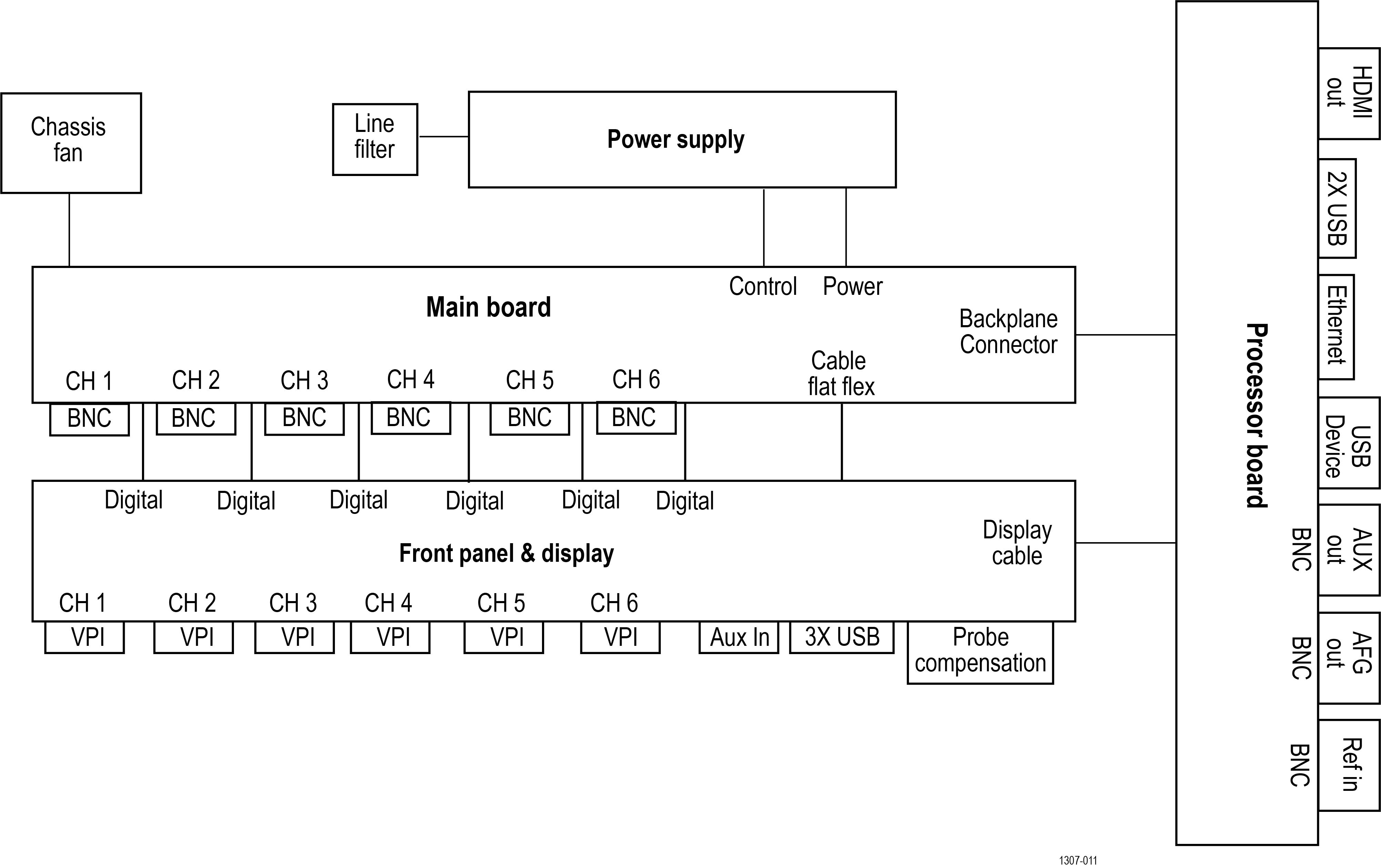
Power supply
The Power Supply board converts AC line voltage to +12 V to power for all internal circuits.
Processor board
The processor board contains the following functions:
- Processor system
- The processor system contains a microprocessor that controls the entire instrument. The processor system also contains the flash memory for the operating system, system RAM, and interfaces to I/O ports and the acquisition system.
- Rear panel I/O ports
- The processor board contains USB ports, an Ethernet port (LAN), a HDMI Video port, the USB-TMC port, an AUX OUT BNC connector, an EXT REF IN BNC connector, and the AFG Out generator BNC connector.
- Other functions
- The processor board also houses the AFG generator, USB-TMC controller and USB host hub.
Main board
The Main board contain the following functions:
- Acquisition system
- The Acquisition system begins with the analog signal path and ends with a digitized signal in memory. The signal enters a channel input, and then passes through an attenuator and preamplifier. The analog signal from each preamplifier goes through a digitizer, and then into acquisition memory. The analog signal from each preamplifier is also distributed to a trigger circuit.
- Analog Front-end
- All of the analog and digital inputs are routed to the analog Front-end circuitry. The analog channels are amplified and attenuated through the front-end circuitry, and are output to the acquisition ASICs. The digital channels simply pass through the front-end circuitry to the acquisition ASICs.
- Power converter
- The Carrier interface assembly converts the +12 V power to all voltages used for the analog and digital circuitry throughout the system. Standby power is used to keep portions of the system powered at all times that AC power is connected to the instrument.
- Other functions
- The Main board interfaces to the Power supply and various cooling fans.
Front panel and display
The Front Panel board contains digital logic that reads the front-panel buttons and controls and sends this information to the processor system on the Processor board. The Front Panel board also generates the probe compensation output signal, provides USB ports on the front panel and houses the main power switch. The front panel routes the digital front-end signals from the probe directly to the main board.
Maintenance
This section contains information needed to perform periodic and corrective maintenance on the instrument.
Preventing ESD
Before servicing this product, read the General Safety Summary and the Service Safety Summary at the front of the manual, as well as the following ESD information.
| CAUTION:Electrostatic discharge (ESD) can damage any semiconductor component in this instrument. |
When performing any service that requires internal access to the instrument, adhere to the following precautions to avoid damaging internal modules and their components due to electrostatic discharge:
- Minimize handling of static-sensitive circuit boards and components.
- Transport and store static-sensitive modules in their static protected containers or on a metal rail. Label any package that contains static-sensitive boards.
- Discharge the static voltage from your body by wearing a grounded antistatic wrist strap while handling these modules.
- Service static-sensitive modules only at a static-free work station.
- Do not allow any items capable of generating or holding a static charge on the work station surface.
- Handle circuit boards by the edges when possible.
- Do not slide the circuit boards over any surface.
- Avoid handling circuit boards in areas that have a floor or work-surface covering capable of generating a static charge.
Adjustment procedures
Adjustment and calibration must be performed by a Tektronix Service Center.
Go to tek.com to find information on contacting Tektronix Service Support.
Adjustment interval
The voltage and timing references inside the instrument are very stable over time and do not need routine adjustment.
If the instrument fails the performance tests in the Specifications and Performance Verification Manual, adjustment may be required. To download the Specification and Performance Verification Manual go to tek.com/support/product-support, search for the model number of your instrument in the field, and select the Specification and Performance Verification document to download under Manuals.
If your organization requires periodic calibration, a general rule is to verify performance and make adjustments (only if needed) every 2000 hours of operation or once a year if the instrument is used infrequently.
Adjustment after repair
After removal and replacement of any module, you must perform the Performance Verification procedures, found in the Specifications and Performance Verification Manual, available to download from tek.com.
If the instrument fails any Performance Verification tests, it must be returned to a Tektronix Service Center for adjustment and calibration.
Inspection and cleaning
This section describes how to inspect for dirt and damage. It also describes how to clean the exterior and interior of the instrument.
Inspection and cleaning are done as preventive maintenance. Preventive maintenance, when done regularly, may prevent instrument malfunction and enhance its reliability.
Preventive maintenance consists of visually inspecting and cleaning the instrument and using general care when operating it.
How often to perform maintenance depends on the severity of the environment in which the instrument is used. A proper time to perform preventive maintenance is just before instrument adjustment.
Exterior cleaning (other than display)
Clean the exterior surfaces of the chassis with a dry lint-free cloth or a soft-bristle brush. If any dirt remains, use a cloth or swab dipped in a 75% isopropyl alcohol solution. Use a swab to clean narrow spaces around controls and connectors. Do not use abrasive compounds on any part of the chassis that may damage the chassis.
Clean the On/Standby switch using a cleaning towel dampened with deionized water. Do not spray or wet the switch itself.
| CAUTION:Avoid the use of chemical cleaning agents which might damage the plastics used in this instrument. Use only deionized water when cleaning the front-panel buttons. Use a 75% isopropyl alcohol solution as a cleaner for cabinet parts. Before using any other type of cleaner, consult your Tektronix Service Center or representative.
|
Inspection - Exterior. Inspect the outside of the instrument for damage, wear, and missing parts. Immediately repair defects that could cause personal injury or lead to further damage to the instrument.
| Item | Inspect for | Repair action |
|---|---|---|
| Cabinet, front panel, and cover | Cracks, scratches, deformations, damaged hardware | Repair or replace defective module |
| Front-panel knobs | Missing, damaged, or loose knobs | Repair or replace missing or defective knobs |
| Connectors | Broken shells, cracked insulation, and deformed contacts. Dirt in connectors | Repair or replace defective modules. Clear or brush out dirt |
| Carrying handle and cabinet feet | Correct operation | Repair or replace defective module |
| Accessories | Missing items or parts of items, bent pins, broken or frayed cables, and damaged connectors | Repair or replace damaged or missing items, frayed cables, and defective modules |
Flat panel display cleaning
Clean the flat panel display surface by gently rubbing the display with a clean-room wipe (such as Wypall Medium Duty Wipes, #05701, available from Kimberly-Clark Corporation), or an abrasive-free cleaning cloth.
If the display is very dirty, moisten the wipeor cloth with distilled water, a 75% isopropyl alcohol solution, or standard glass cleaner, and gently rub the display surface. Use only enough liquid to dampen the cloth or wipe. Avoid using excess force or you may damage the display surface.
| CAUTION:Improper cleaning agents or methods can damage the flat panel display.
|
| CAUTION:To prevent getting moisture inside the instrument during external cleaning, do not spray any cleaning solutions directly onto the screen or instrument.
|
Interior cleaning
You can only clean the interior of the rear chassis assembly. To access the rear chassis assembly, see the Removal and Installation Procedures topics.
Do not disassemble or clean the front chassis assembly (other than cleaning the front panel display and removing panel knobs). Disassembling the front chassis assembly requires that the instrument be returned to your nearest Tektronix Service Center for calibration.
| WARNING:To avoid electric shock or damage to the instrument, remove instrument power. Before performing any procedure that follows, power down the instrument and disconnect it from line voltage.
|
- Blow off dust with dry, low-pressure (approximately 9 psi), deionized air.
- Use a soft-bristle, non-static-producing brush for cleaning around components.
- Remove any remaining dust with a lint-free cloth dampened in isopropyl alcohol (75% solution). (A cotton-tipped applicator is useful for cleaning in narrow spaces and on circuit boards).
- If you must use a liquid for minor rear chassis interior cleaning, use a clean-room wipe (such as Wypall Medium Duty Wipes, #05701, available from Kimberly-Clark Corporation) dampened with a 75% isopropyl alcohol solution.
- Inspect the internal portions of the instrument for damage and wear. See Table 1. Defects should be repaired immediately.
- If any circuit board is repaired or replaced, you must perform the Performance Verification procedure in the specifications and performance verification manual, which was provided with your instrument. This manual is also available at www.tektronix.com/manuals, by searching for your product name. If the instrument fails the Performance Verification tests, it must be returned to a Tektronix Service Center for repair and calibration.
| CAUTION:To prevent damage from electrical arcing, ensure that circuit boards and components are dry before applying power to the instrument.
|
| Item | Inspect for | Repair action |
|---|---|---|
| Circuit boards | Loose, broken, or corroded solder connections. Burned circuit boards. Burned, broken, or cracked circuit-run plating. | Remove and replace damaged circuit board. |
| Resistors | Burned, cracked, broken, blistered condition. | |
| Capacitors | Damaged or leaking cases. Corroded solder on leads or terminals. | |
| Wiring and cables | Loose plugs or connectors. Burned, broken, or frayed wiring. | Firmly seat connectors. Replace defective cables. |
| Chassis | Dents, deformations, and damaged hardware. | Straighten, repair, or replace defective hardware. |
Lubrication
There is no periodic lubrication required for this instrument.
Returning instrument for service
Use the following instructions for returning your instrument for service.
When repacking the instrument for shipment, use the original packaging. If the packaging is not available or unfit for use, contact your local Tektronix representative to obtain new packaging.
If you need to return your instrument for repair or calibration, call 1-800-438-8165 or complete the form at tek.com/services/repair/rma-request. When you request service, have the serial number, firmware, and software version of the instrument.
If you want to see the warranty or service agreements on your products, or if you want to create your own service price estimate, visit our quick service quote site at tek.com/service-quote.
Removal and replacement procedures
This section contains procedures for removal and installation of replaceable modules in the instrument. Refer to the Replaceable parts section for lists and exploded views of replaceable modules.
Any module inside of the chassis that does not have a remove and replace procedure requires that the entire instrument be returned to Tektronix Service Center for service.
| WARNING:Before performing this or any other procedure in this manual, read the safety summaries found at the beginning of this manual. Also, to prevent possible injury to service personnel or damage to the instrument components, read Preventing ESD. Before performing any procedure in this subsection, disconnect the power cord from the line voltage source. Failure to do so could cause serious injury or death. |
| Note:Read the cleaning procedure before disassembling the instrument for cleaning. |
Required equipment
Most assemblies in this instrument can be removed with a T-10 or T8 Torx® screwdriver tip.
| Name | Description |
|---|---|
| Screwdriver handle | Accepts Torx-driver bits |
| T-10 Torx tip | Used for removing instrument screws. Torx-driver bit for T-10 size screw heads |
| T-8 Torx tip | Used for removing instrument screws. Torx-driver bit for T-8 size screw heads |
| 9/16 inch open-end wrench | Used to remove nut posts |
| Proper antistatic work environment | To prevent electrostatic damage to components whenever you work on the instrument, wear properly-grounded electrostatic prevention wrist and foot straps, and work in a tested antistatic environment on an antistatic mat. |
Remove the front-panel knobs
The following procedure describes the removal and replacement of the front-panel knob assemblies.
Before you begin
To prevent electrostatic damage to components whenever you work on the instrument, wear properly-grounded electrostatic prevention wrist and foot straps, and work in a tested antistatic environment on an antistatic mat.
About this task
There are eight knob assemblies that can be removed from the front case.
Procedure
Results
To reinstall a knob, align the knob with the shaft indent and push the knob onto the shaft. Turn the knob to make sure there is a smooth rotation.
Remove instrument feet
The following procedure describes the removal and replacement of the instrument feet.
Before you begin
To prevent electrostatic damage to components whenever you work on the instrument, wear properly-grounded electrostatic prevention wrist and foot straps, and work in a tested antistatic environment on an antistatic mat.
About this task
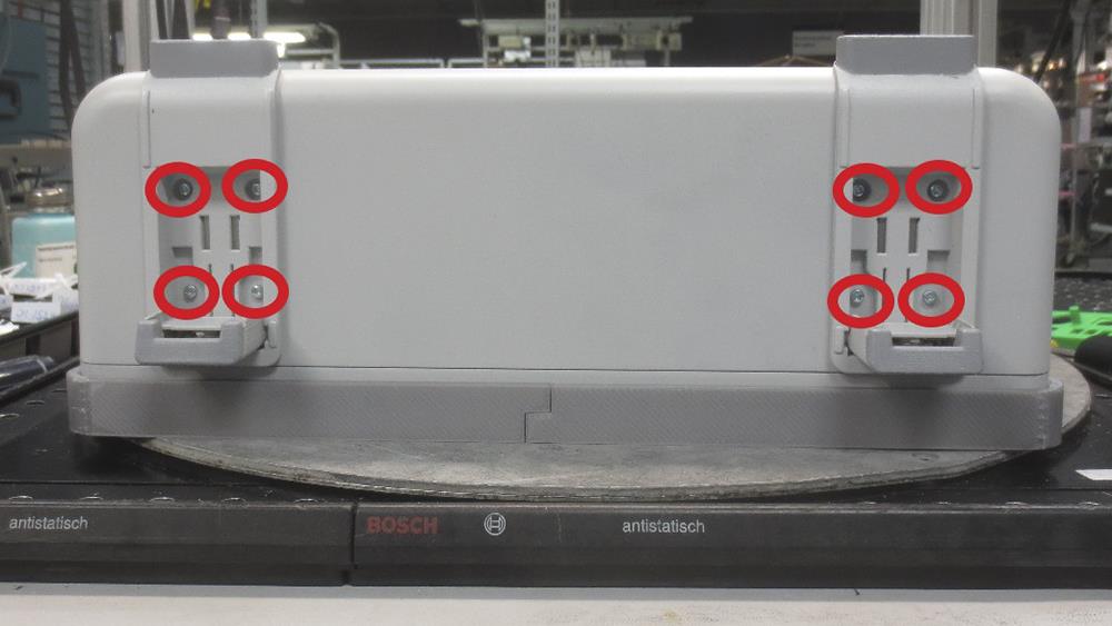
There are two feet that can be removed from the bottom of the instrument.
Procedure
- Use a screwdriver with T-10 Torx tip to remove the four screws from each foot assembly.

Results
To reinstall, reverse the above steps. Use a screwdriver with T-10 Torx tip to secure the eight screws. First insert and tighten the screws that are near the front edge of the instrument, then insert and tighten the screws that are near the rear edge of the instrument. Tighten to 0.65 N·m.
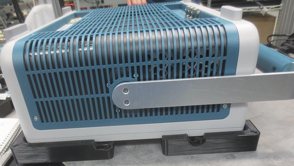
Remove the handle
The following procedure describes the removal and replacement of the handle.
Before you begin
To prevent electrostatic damage to components whenever you work on the instrument, wear properly-grounded electrostatic prevention wrist and foot straps, and work in a tested antistatic environment on an antistatic mat.
Procedure
- Use a screwdriver with T-10 Torx tip to remove two screws from each side of the handle.
- Disengage the handle from the pins on the couplers and remove the handle.
Results
To reinstall, reverse the above steps. Use a screwdriver with T-10 Torx tip to secure the screws. Tighten to 0.65 N·m.
Remove the rear grill and case
The following procedure describes the removal and replacement of the rear grill and case.
Before you begin
To prevent electrostatic damage to components whenever you work on the instrument, wear properly-grounded electrostatic prevention wrist and foot straps, and work in a tested antistatic environment on an antistatic mat.
Procedure
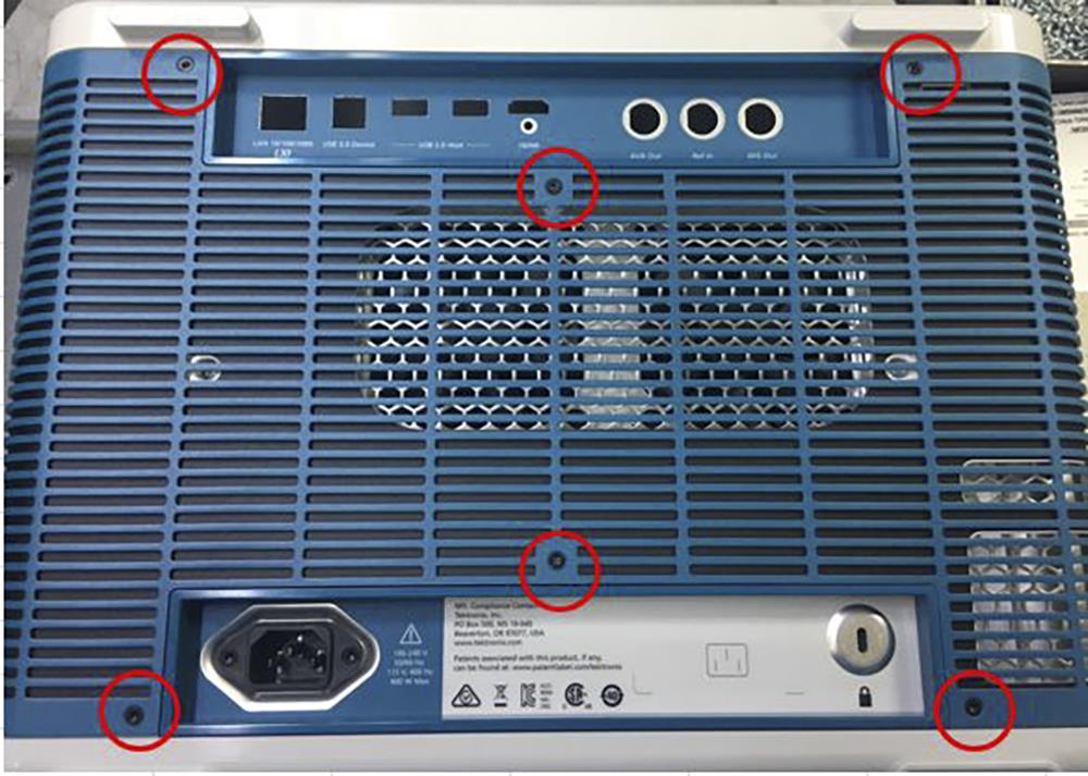
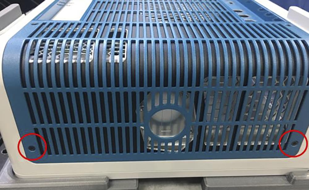
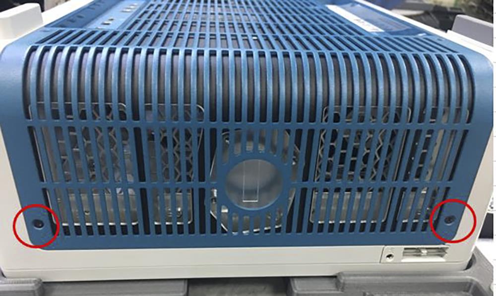
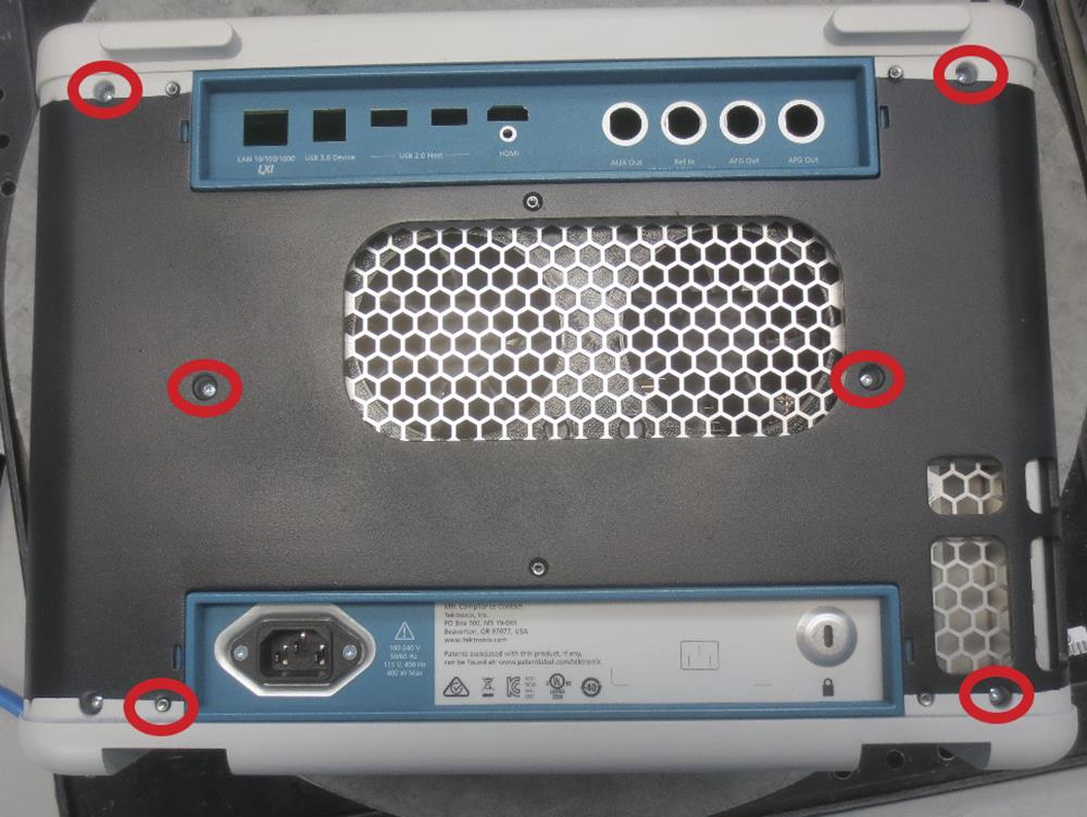
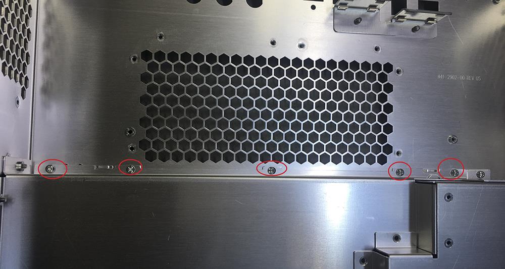
- Use a screwdriver with T-10 Torx tip to remove the 10 screws securing the grill to the rear case.
- Use a screwdriver with T-10 Torx tip to remove the six screws securing the rear case to the rear chassis.
Results
To reinstall, reverse the above steps. Tighten the six T-10 Torx rear case screws to 0.65 N·m.
Remove the rear chassis assembly
The following procedure describes the removal and replacement of the rear chassis assembly.
Before you begin
To prevent electrostatic damage to components whenever you work on the instrument, wear properly-grounded electrostatic prevention wrist and foot straps, and work in a tested antistatic environment on an antistatic mat.
Remove the rear grill and case.
Procedure
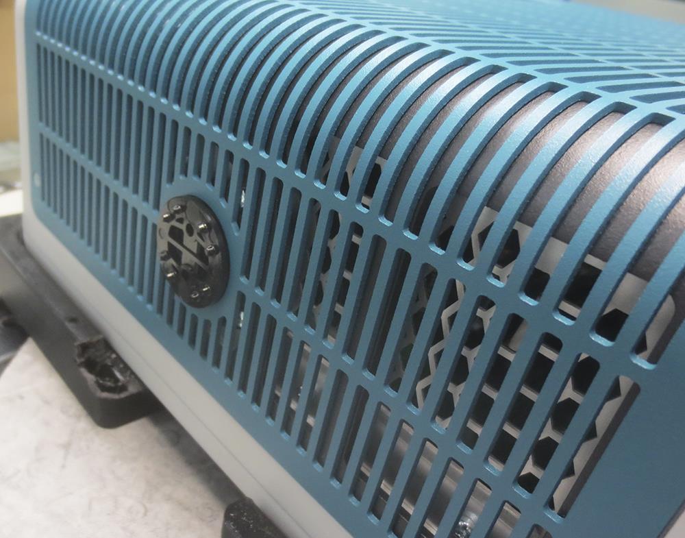
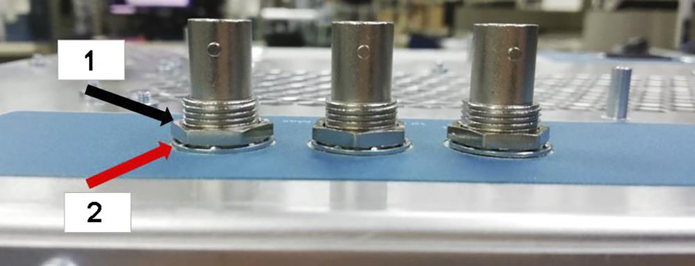
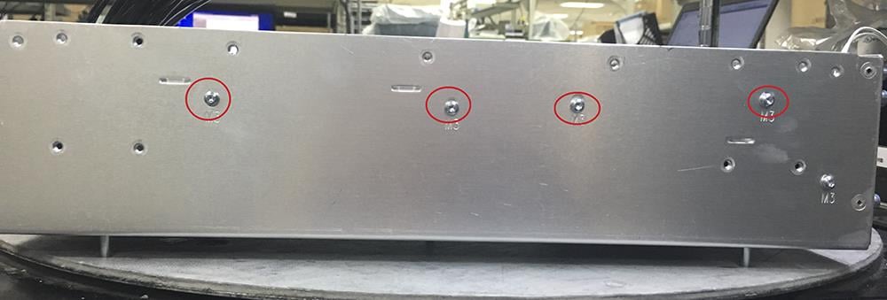
- Use a 9/16" socket to remove BNCs with three washers and three nuts.
Black arrow is for nut and red arrow is for washer.
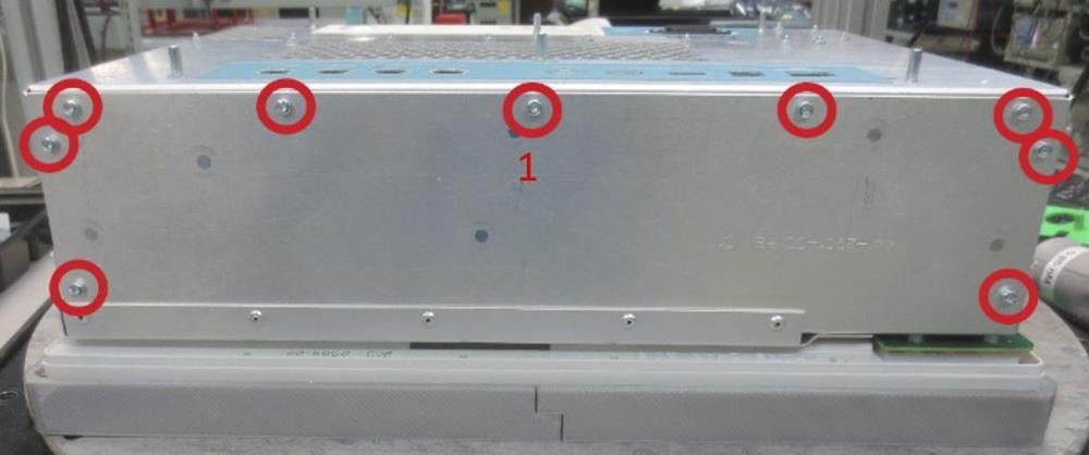
- Use a screwdriver with a with T-10 Torx tip to remove the 25 screws securing the rear chassis to the front chassis.
- Carefully lift the rear chassis off of the front chassis and disconnect the power cables, fan cables, and line filter cable.
Results
To reinstall, reverse the above steps. Tighten the 25 screws with T-10 bit to 0.65 N·m.
Secure BNCs with three washers and three nuts using 9/16" socket and 2.5 N.M hand driver.
Remove the power supply bracket
The following procedure describes the removal and replacement of the power supply bracket.
Before you begin
- To prevent electrostatic damage to components whenever you work on the instrument, wear properly-grounded electrostatic prevention wrist and foot straps, and work in a tested antistatic environment on an antistatic mat.
- Remove the rear grill and case.
- Remove the rear chassis assembly.
Procedure
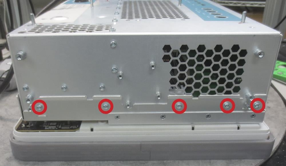
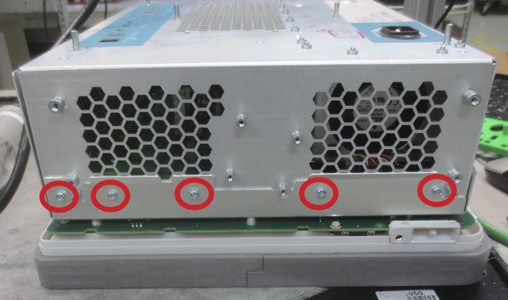
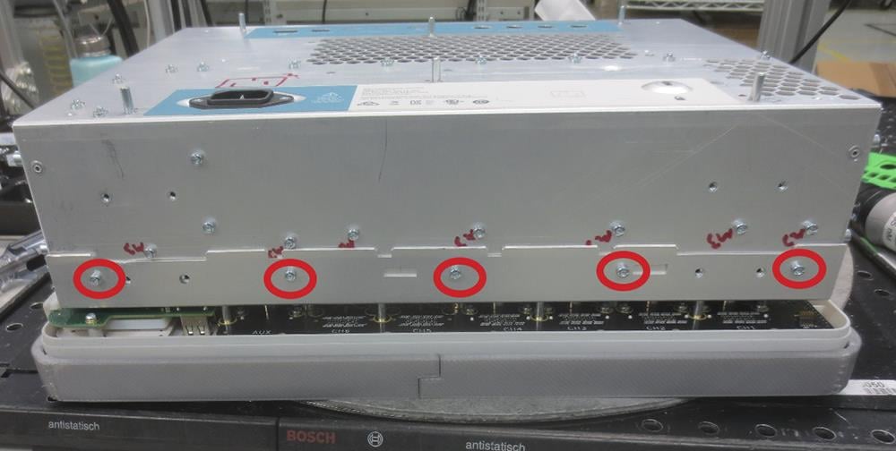
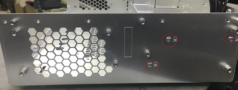
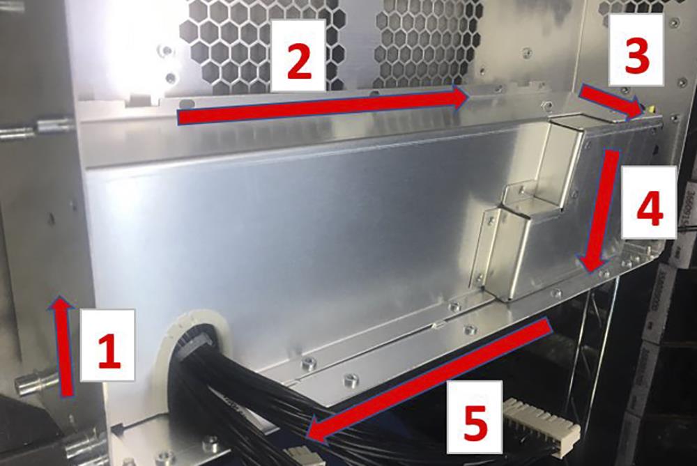
- Use a screwdriver with a with T-10 Torx tip to remove the 15 screws from the power supply bracket.
Results
To reinstall, reverse the above steps. Tighten the 15 screws with T-10 bit to 0.65 N·m. to attach the power supply bracket to chassis with the order of the red arrow.
Remove the power supply
The following procedure describes the removal and replacement of the power supply.
Before you begin
- To prevent electrostatic damage to components whenever you work on the instrument, wear properly-grounded electrostatic prevention wrist and foot straps, and work in a tested antistatic environment on an antistatic mat.
- Remove the rear grill and case.
- Remove the rear chassis assembly.
Procedure
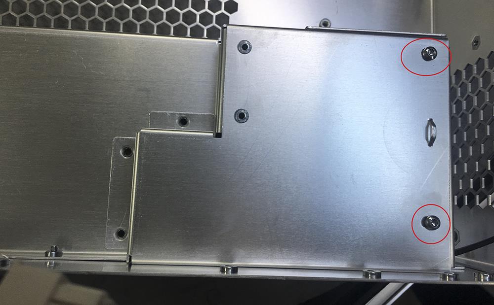
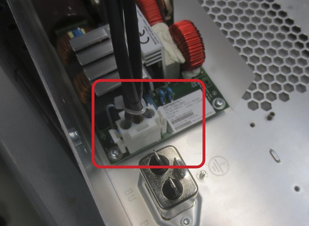
- Disconnect the line input cable from the power supply.
- Use a T-10 Torx screwdriver to remove the seven screws from the power supply.
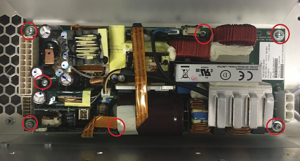
Results
To reinstall, reverse the steps. Tighten the T-10 Torx screws to 0.65 N·m when reinstalling.
Remove the main fan assembly
The following procedure describes the removal and replacement of the power supply bracket.
Before you begin
- To prevent electrostatic damage to components whenever you work on the instrument, wear properly-grounded electrostatic prevention wrist and foot straps, and work in a tested antistatic environment on an antistatic mat.
- Remove the rear grill and case.
- Remove the rear chassis assembly.
Procedure
- Use a T-10 Torx screwdriver to remove the seven screws from the main fan assembly bracket.
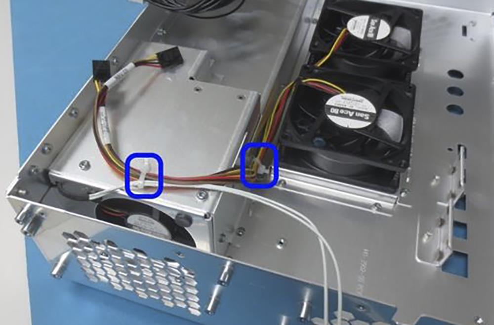
- Remove the cable ties and main fan assembly from the rear chassis.
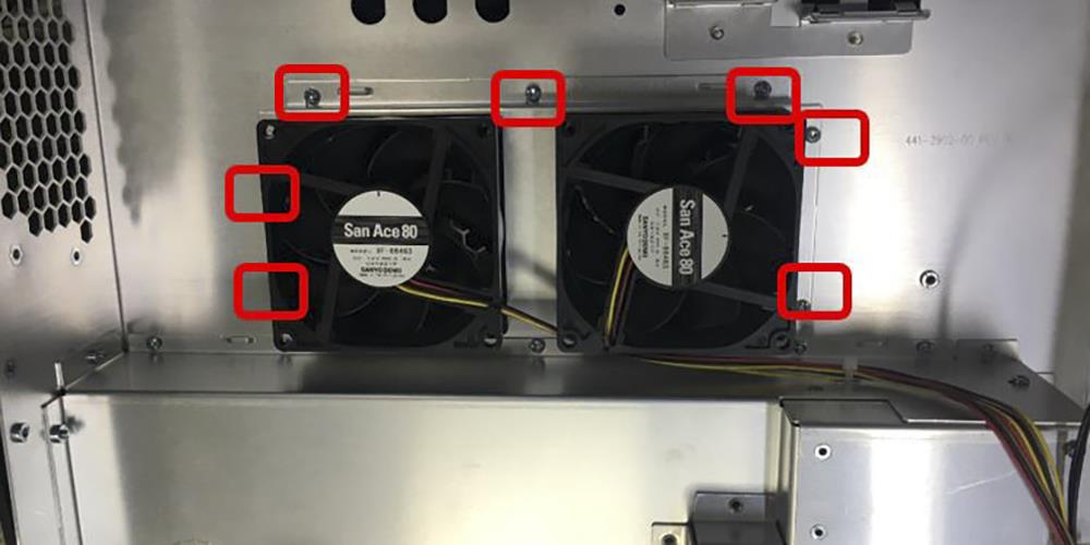
Results
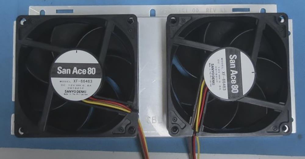
To reinstall, reverse the steps. Install the fan on the bracket in the correct orientation for the fan power cable (see photo). Use a needle nose pliers to reinstall the fan elastic attachments on each corner. Tighten the T-10 Torx screws to 0.65 N·m when reinstalling.
When reinstalling the cable ties, include the power supply fan cable on the top cable tie location.
Remove the main board
The following procedure describes the removal and replacement of the main board.
Before you begin
- To prevent electrostatic damage to components whenever you work on the instrument, wear properly-grounded electrostatic prevention wrist and foot straps, and work in a tested antistatic environment on an antistatic mat.
- Remove the front chassis assembly.
- Remove the processor board.
Procedure
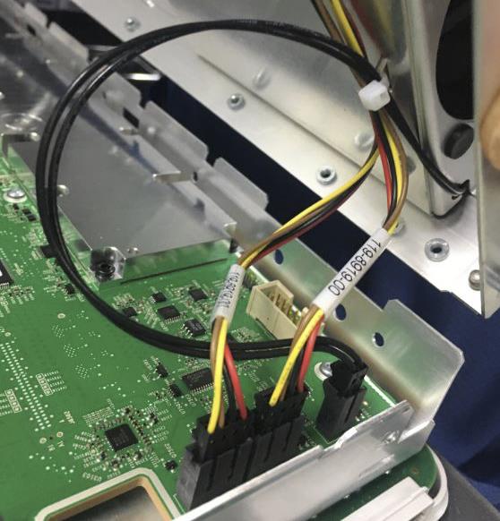
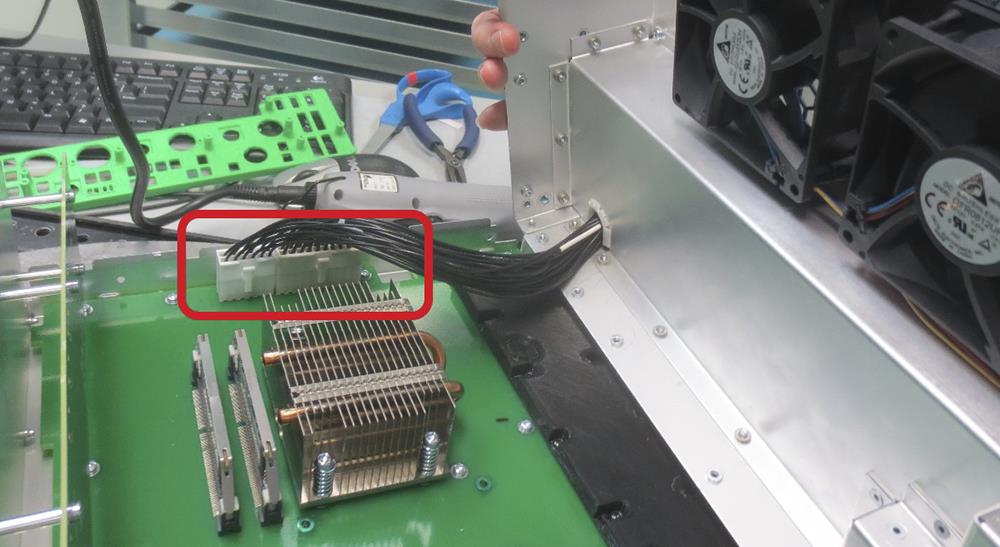
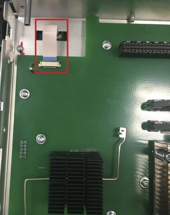
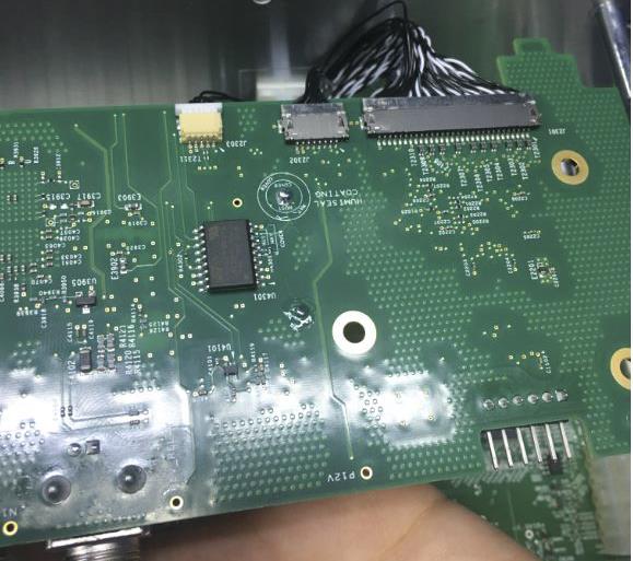
- Disconnect the front panel cable from the main board as shown below.
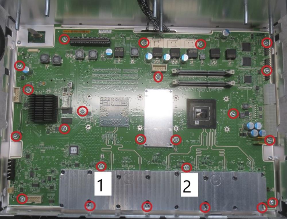
- Use a T-10 Torx screwdriver to remove the 23 screws that have attached the main board to the front chassis assembly.
Results
To reinstall, reverse the above steps. Tighten the T-10 Torx screws to 0.65 N·m when reinstalling.
Remove the processor board
The following procedure describes the removal and replacement of the processor board.
Before you begin
- To prevent electrostatic damage to components whenever you work on the instrument, wear properly-grounded electrostatic prevention wrist and foot straps, and work in a tested antistatic environment on an antistatic mat.
- Remove the front chassis assembly.
Procedure
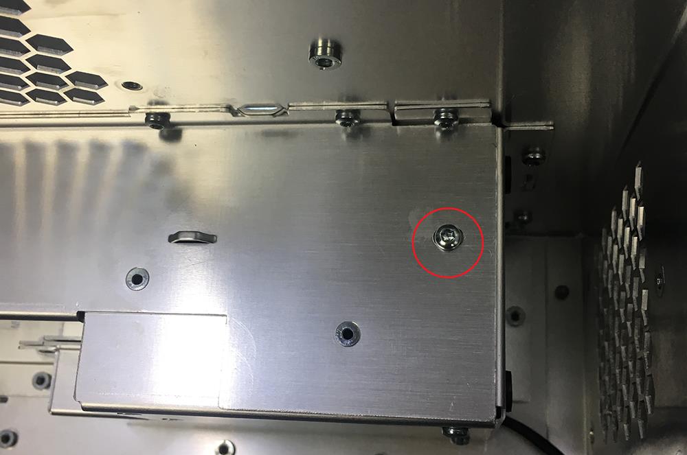
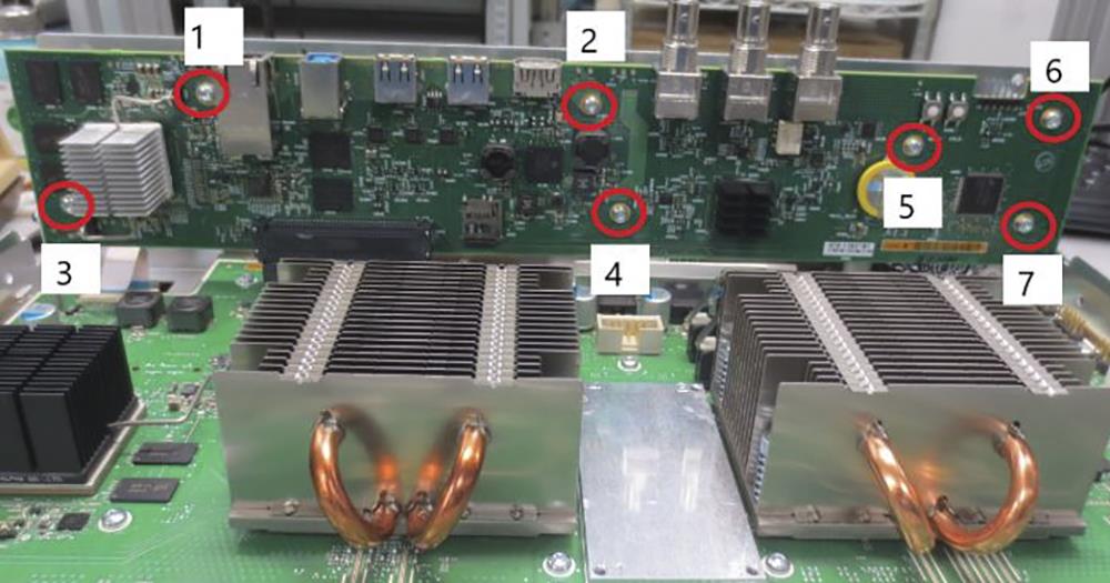
- Use a T-10 Torx screwdriver to remove the seven screws that have attached the processor board to the front chassis assembly.
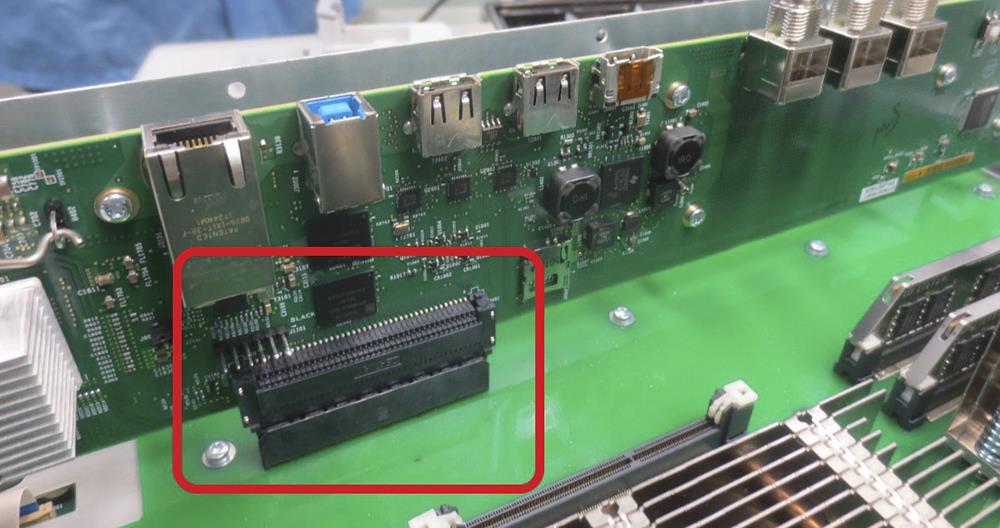
- Carefully disconnect the processor board from the main board.
- Disconnect the display cable from the processor board as shown below.
Results
To reinstall, reverse the above steps. Tighten the T-10 Torx screws to 0.65 N·m when reinstalling.
Troubleshooting
This section contains information and procedures designed to help you isolate faults to a module.
| CAUTION:Before performing this or any other procedure in this manual, read the General Safety Summary and Service Safety Summary found at the beginning of this manual. To prevent possible injury to service personnel or damage to electrical components, please read information on Preventing ESD. |
This section requires that service personnel have the appropriate skills to work on this instrument, including PC troubleshooting and Microsoft Windows operating system skills. Details of PC and Windows operation and service are not in this manual.
For assistance, contact your local Tektronix Service Center.
Service level
This subsection contains information and procedures to help you determine if a faulty power supply is the problem with your instrument. For a faulty power supply, return the instrument to a Tektronix Service Center for repair.
Check for common problems
Use the following table to help isolate possible failures. The table lists problems and possible causes. The list is not exhaustive, but it may help you eliminate a problem that is quick to fix, such as a loose power cord. For more detailed troubleshooting, see the Troubleshooting flow chart.
| Symptom | Possible cause(s) |
|---|---|
| Instrument will not power on | Power cord not plugged in |
| Faulty power supply | |
| Instrument powers on, but one or more fans will not operate | Faulty fan power cable |
| Fan power cable not connected to circuit board | |
| Defective fan | |
| Faulty power supply | |
| One or more defective point of load regulators | |
| Flat-panel display blank or has streaks in display | Faulty LCD screen or video circuitry |
| Touch sensor in display does not work or has limited use | Display cable not fully seated on display assembly |
| Display cable not fully seated on processor board |
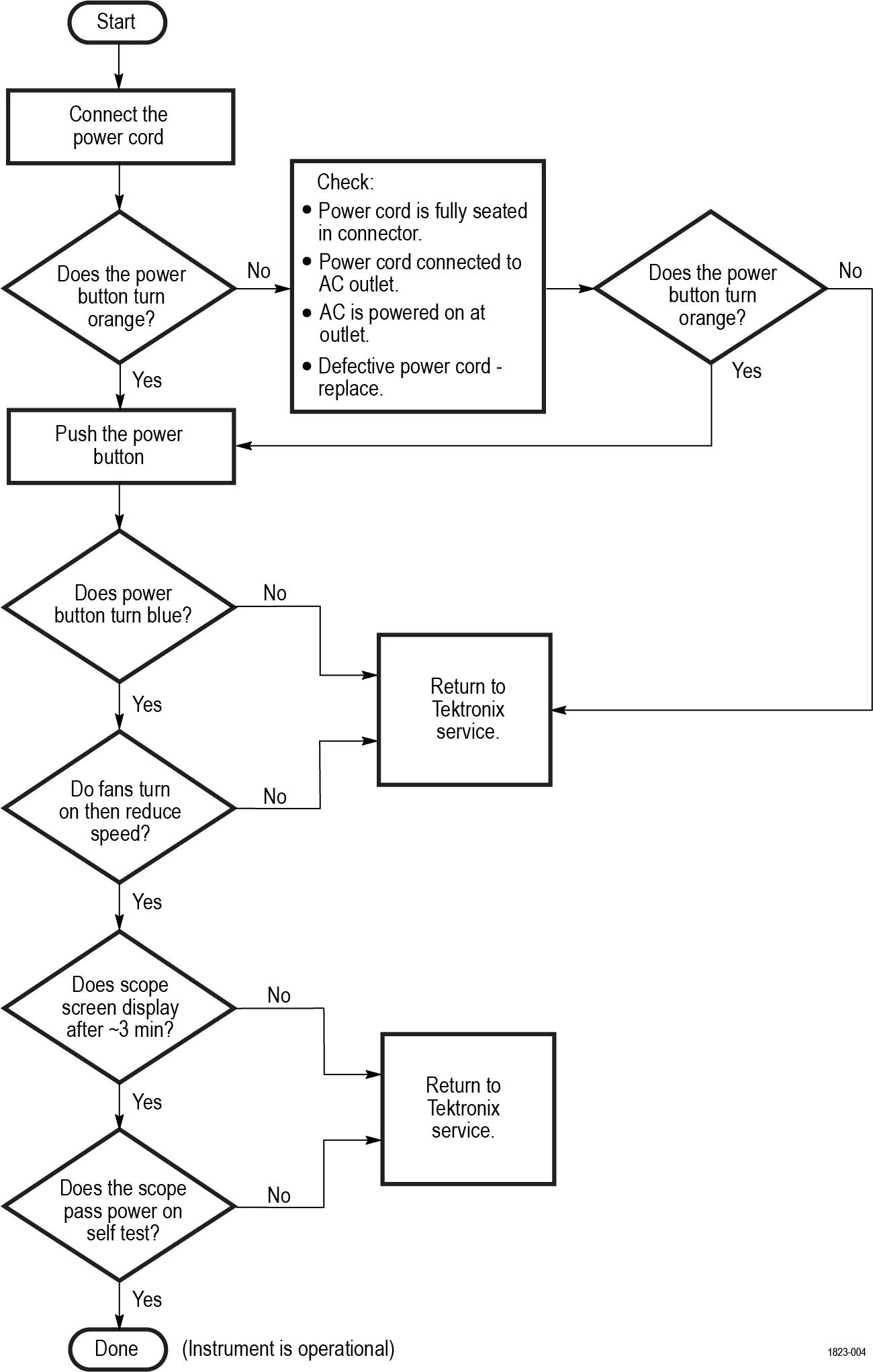
Troubleshooting flow chart
Follow the troubleshooting flow chart to determine the action for a fault condition.
Instrument self tests
The instrument runs self test diagnostics during every power on. The power on self tests ensure that the hardware and software are functionally working. The tests provide limited diagnostic information, and provide no performance information.
If the instrument detects errors during power on, a pop-up message indicates that a failure has occurred. To display the Self test menu and results, select Utility > Self Test. Select a test mode and run the self tests. If you continue to get errors on one or more tests, you will need to return the instrument to your nearest Tektronix Service Center for repair.
Software updates
To update the application software:
- Go to www.tek.com/product-support.
- Enter a model number (MSO44 or MSO46) in the Enter Product or Product Series Name field and click Go. Any 4 Series model number will do, as all models use the same software update.
- Click the Software tab.
- On the oscilloscope, tap Help > About.
- Compare the version number of the installed software to the version on the web:
- If the version number on the oscilloscope is the same as the version on the web, you have the latest version. You do not need to install new software. Exit this procedure.
- If the version number on the oscilloscope is a lower number than the version on the web, you can download and install new software. Continue with the rest of this procedure.
- Select the highest-numbered version (4 Series MSO Embedded OS Firmware - VX.X).
- Click Download File to start the download.
- When done downloading, unzip the downloaded file.
- Open the file install.txt and follow the instructions in the file.
After repair
After removal and replacement of the power supply module, you must perform the Performance Verification procedures, found in the Specifications and Performance Verification Manual. Download all instrument manuals from tek.com.
If the instrument fails the Performance Verification tests, it must be returned to a Tektronix Service Center for adjustment.
Replaceable parts
This section contains separate subsections for different product groups. Use the lists in the appropriate section to identify and order replacement parts for your product. The standard accessories your instrument are listed on tek.com.
Replacement parts are available through your local Tektronix field office or representative.
Parts ordering information
Changes to Tektronix products are sometimes made to accommodate improved components as they become available and to give you the benefit of the latest improvements. Therefore, when ordering parts, it is important to include the following information in your order:
- Part number
- Instrument type or model number
- Instrument serial number
- Instrument modification number, if applicable
If you order a part that has been replaced with a different or improved part, your local Tektronix field office or representative will contact you concerning any change in part number.
Module servicing
Modules can be serviced by selecting one of the following three options. Contact your local Tektronix Service Center or representative for repair assistance.
Module exchange. In some cases, you may exchange your module for a re-manufactured module. These modules cost significantly less than new modules and meet the same factory specifications. For more information about the module exchange program, call 1-800-833-9200. Outside North America, contact a Tektronix sales office or distributor; see tek.com for a list of offices.
Module repair and return. You may ship your module to Tektronix for repair, after which it will be returned to you.
New modules. You may purchase replacement modules in the same way as other replacement parts.
Abbreviations
Abbreviations conform to American National Standard ANSI Y1.1-1972.
Using the replaceable parts list
Use the following table describes each column in the parts list.
| Column | Column name | Description |
|---|---|---|
| 1 | Figure & index number | Items in this section are referenced by figure and index numbers to the exploded view illustrations that follow. |
| 2 | Tektronix part number | Use this part number when ordering replacement parts from Tektronix. |
| 3 and 4 | Serial number | Column three indicates the serial number at which the part was first effective. Column four indicates the serial number at which the part was discontinued. No entry indicates the part is good for all serial numbers. |
| 5 | Qty | This indicates the quantity of parts used. |
| 6 | Name & description | An item name is separated from the description by a colon (:). Because of space limitations, an item name may sometimes appear as incomplete. Use the U.S. Federal Catalog handbook H6-1 for further item name identification. |
Rear case assembly with handle and feet
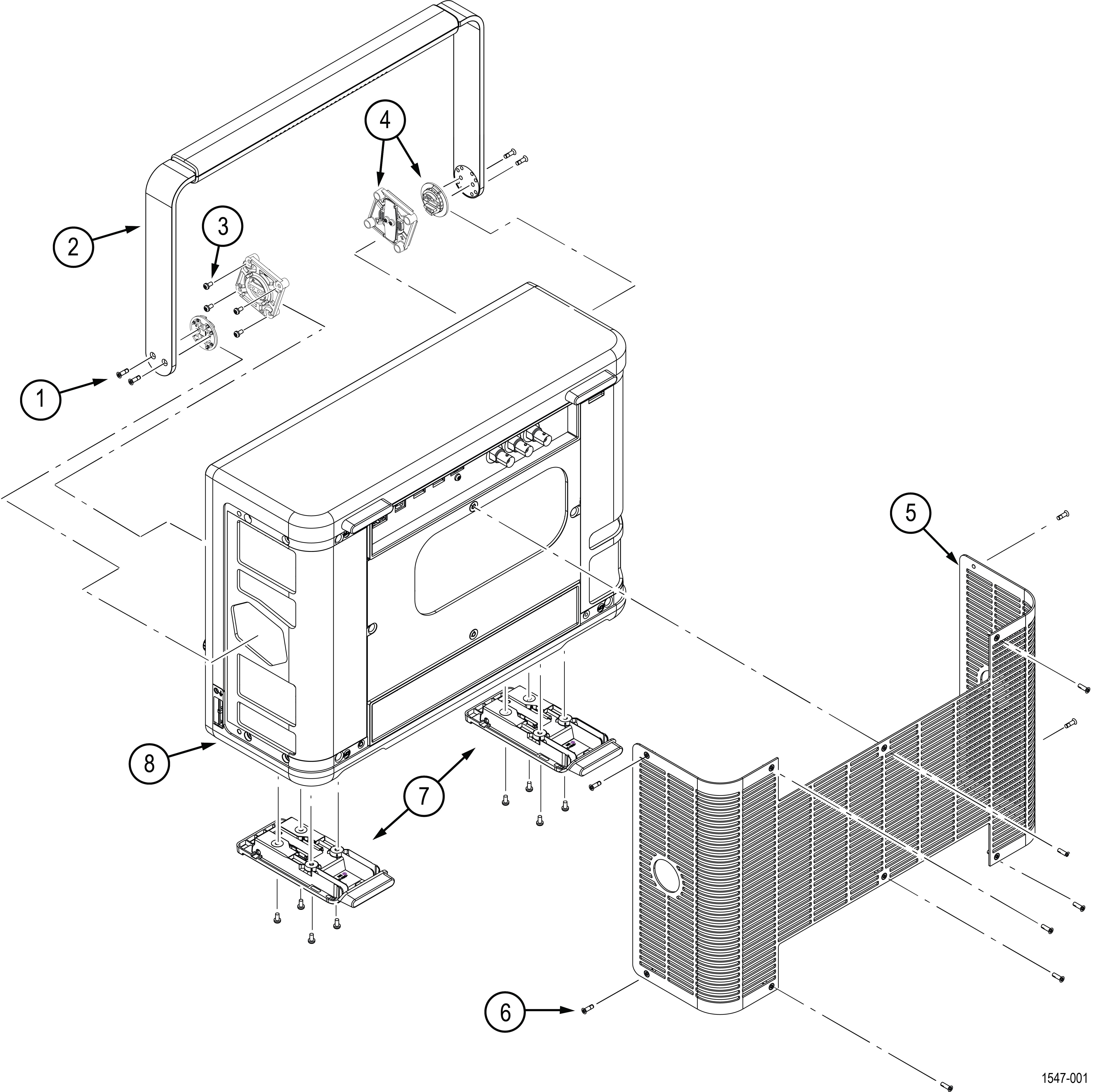
| Index number | Part number | Serial no. effective | Serial no. discont'd | Qty | Description |
|---|---|---|---|---|---|
| -1 | 211-1688-XX | 4 | SCREW, MACHINE, M3X0.5X10, FLAT HEAD 90 DEG, SUS410 NYLOK, TORX T10 | ||
| -2 | 050-3906-XX | 1 | MODULE ASSY:SERVICE REPLACEMENT KIT, HANDLE METAL BASE W/PLASTIC GRIP AND HARDWARE, MSO4 SERIES | ||
| -3 | 211-1636-XX | 4 |
SCREW, MACHINE, M3x0.5x8MM PAN HEAD, TORX T10 WITH NYLON PATCH | ||
| -4 | 065-1058-XX | 1 | MODULE ASSY:SERVICE REPLACEMENT KIT;HANDLE HUB LEFT AND RIGHT (SET), MSO4 SERIES | ||
| -5 | 378-0961-XX | 1 | GRILL, COSMETIC, REAR, MSO4K SERIES, SAFETY CONTROLLED | ||
| -6 | 211-1686-XX | 12 | SCREW, MACHINE; M3X0.5X10, FLAT HEAD, STL, TORX 10 | ||
| -7 | 065-1047-XX | 2 | MODULE ASSY:SERVICE REPLACEMENT KIT;REAR FLIP FEET, MSO4 SERIES | ||
| -8 | 202-0567-XX | 1 | CASE, REAR, MSO4K SERIES, SAFETY CONTROLLED |
Front display assembly
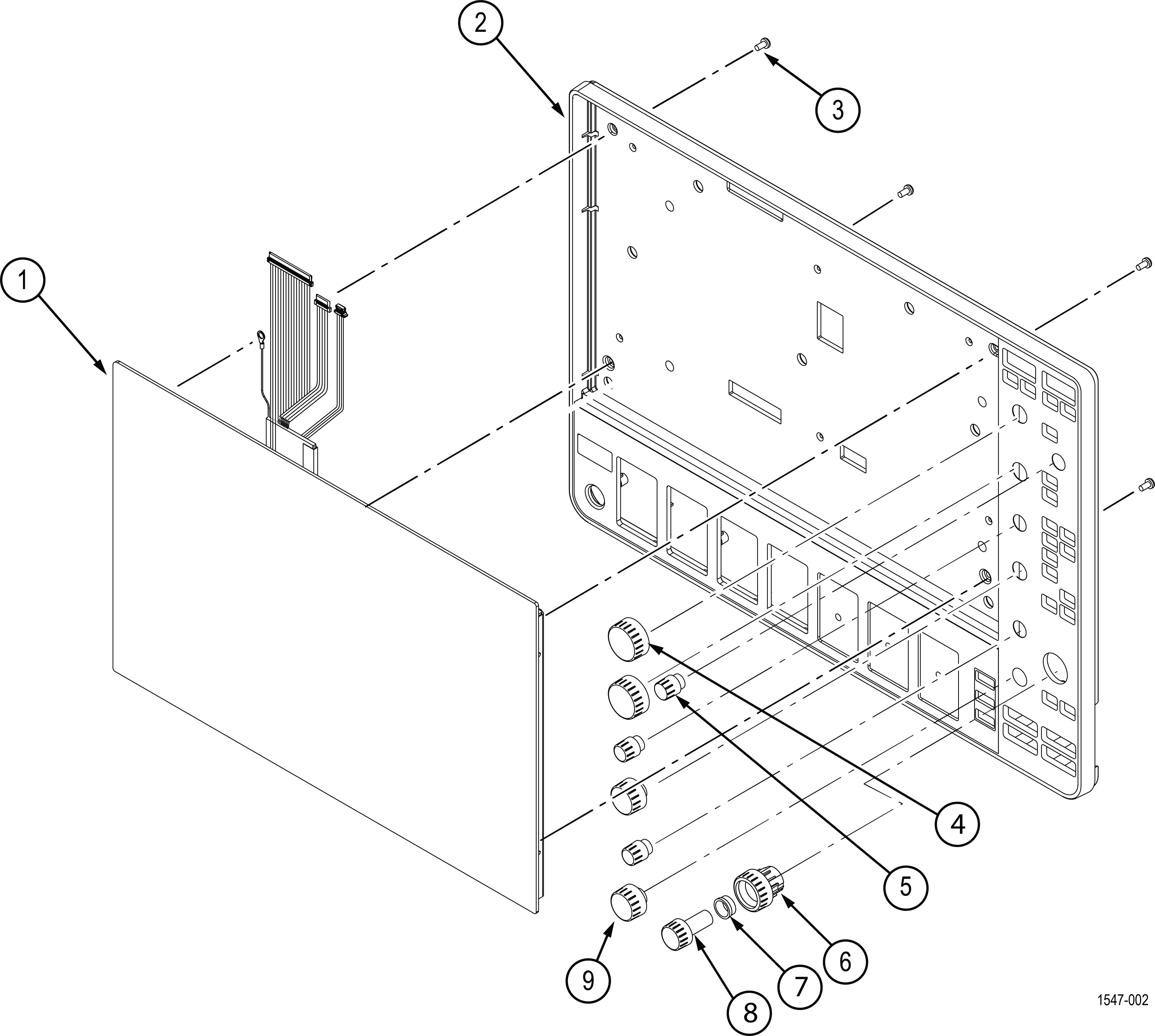
| Index number | Part number | Serial no. effective | Serial no. discont'd | Qty | Description |
|---|---|---|---|---|---|
| -1 | 065-1052-XX | 1 | MODULE ASSY:SERVICE REPLACEMENT KIT;DISPLAY/TOUCH SCREEN ASSY Return the instrument to Tektronix for service. | ||
| -2 | 065-1056-XX | 1 | MSO46: MODULE ASSY:SERVICE REPLACEMENT KIT;6CH FRONT CASE WITH LABELS | ||
| 065-1055-XX | 1 | MSO44: MODULE ASSY:SERVICE REPLACEMENT KIT;4CH FRONT CASE WITH LABELS | |||
| -3 | 211-1584-XX | 4 | SCREW, MACHINE, M3X0.5X6 MM PAN HEAD, TORX T10 | ||
| -4 | 366-0945-XX | 1 | ASSEMBLY, KNOB, LARGE WITH OVERMOLD | ||
| -5 | 366-0943-XX | 1 | ASSEMBLY, KNOB, SMALL WITH OVERMOLD | ||
| -6 | 366-0946-XX | 1 | ASSEMBLY, KNOB, PAN WITH OVERMOLD | ||
| -7 | 358-0890-XX | 1 | BUSHING, SPACER, RING JOG-SHUTTLE | ||
| -8 | 366-0947-XX | 1 | ASSEMBLY, KNOB, ZOOM WITH OVERMOLD | ||
| -9 | 366-0944-XX | 1 | ASSEMBLY, KNOB, MEDIUM WITH OVERMOLD |
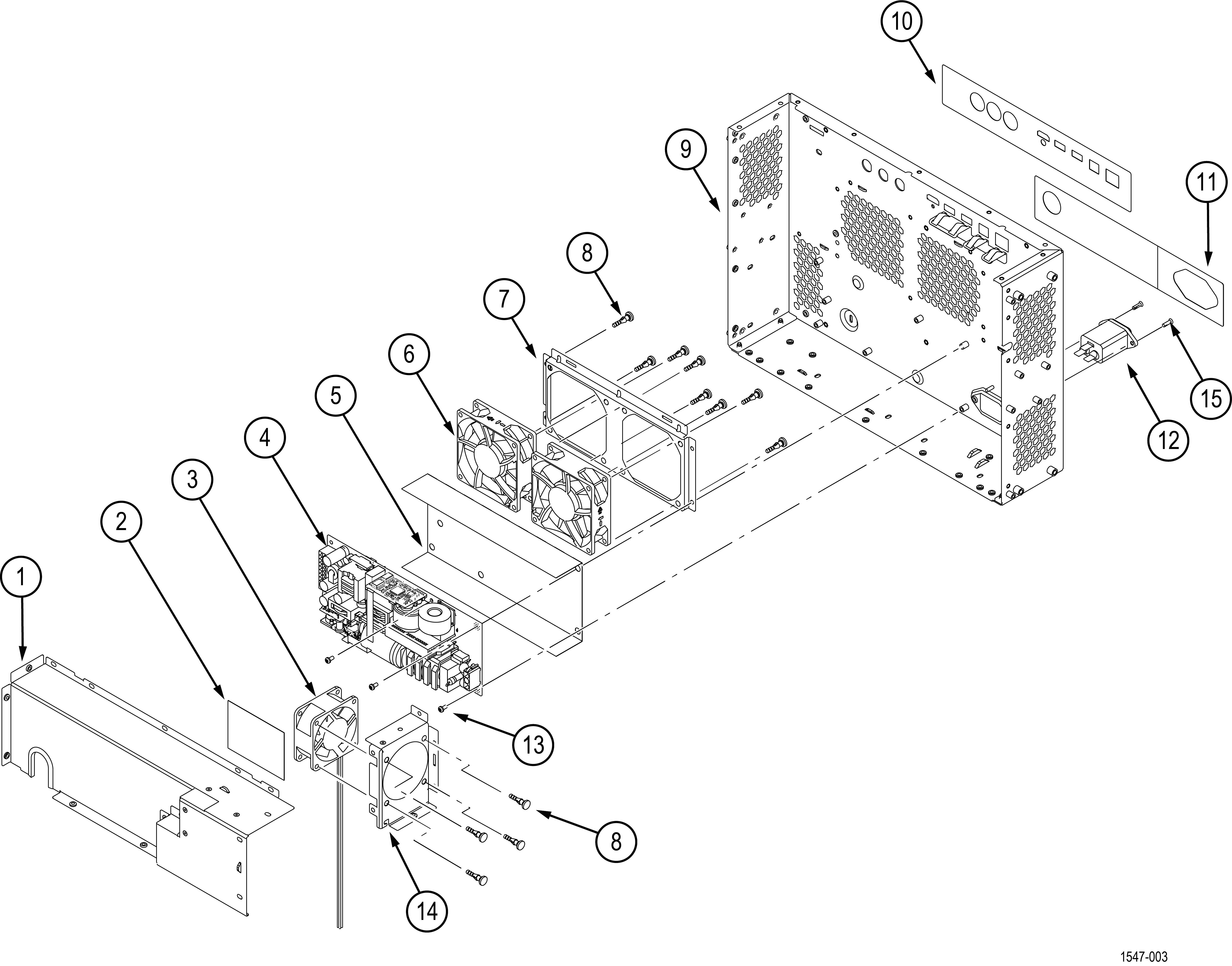
Rear chassis assembly with power supply and fans
| Index number | Part number | Serial no. effective | Serial no. discont'd | Qty | Description |
|---|---|---|---|---|---|
| -1 | 407-6131-XX | 1 | BRACKET, POWER SUPPLY, 750W | ||
| -2 | 337-4731-XX | 1 | SHIELD, INSULATOR, POWER SUPPLY, SAFETY CONTROLLED | ||
| -3 | 119-8939-XX | 1 | FAN WITH 2X2 CONN, 60X25MM, 12V, SAFETY CONTROLLED | ||
| -4 | 119-9093-XX | 1 | POWER SUPPLY: 400W(MAX),AC-DC,OPEN FRAME; 90-264VAC,47-63 HZ IN; [email protected], +5V@2A, [email protected] OUT; SAFETY CONTROLLED | ||
| -5 | 337-4717-XX | 1 | SHIELD, MOUNT, POWER SUPPLY, SAFETY CONTROLLED | ||
| -6 | 119-8919-XX | 1 | FAN ASSEMBLY, SAN ACE 9GA0812P4J0011 W/ TERMINATION, SAFETY CONTROLLED | ||
| -7 | 407-6151-XX | 1 | BRACKET, 2 FANS | ||
| -8 | 348-2082-XX | 12 | GROMMET, FAN MOUNT, NOISE DAMPING | ||
| -9 | 441-2902-XX | 1 | CHASSIS, REAR | ||
| -10 | 335-4011-XX | 1 | LABEL, REAR, IO, TOP | ||
| -11 | 335-4012-XX | 1 | LABEL, REAR, IO, BOTTOM | ||
| -12 | 119-8742-XX | 1 | FILTER, EMI, AC LINE FILTER, CHASSIS MOUNT, FN9244R10-06, SAFETY CONTROLLED | ||
| -13 | 211-1584-XX | 7 | SCREW, MACHINE, M3X0.5X6MM PAN HEAD, TORX T10 | ||
| -14 | 407-6130-XX | 1 | BRACKET, POWER SUPPLY, FAN | ||
| -15 | 211-1686-XX | 2 | SCREW, MACHINE; M3X0.5X10, FLAT HEAD, STL, TORX 10 |
Front panel assembly
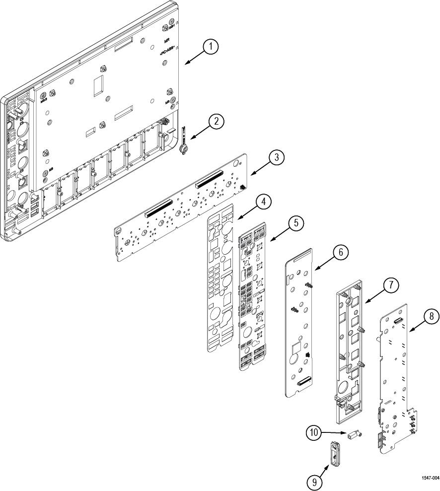
| Note:None of the components listed are user-replaceable. Return the instrument to your nearest Tektronix Service Center to repair or replace any internal components or assemblies in this diagram. |
| Index number | Part number | Serial no. effective | Serial no. discont'd | Qty | Description |
|---|---|---|---|---|---|
| -1 | 202-0564-XX | 1 | CASE, FRONT Return the instrument to Tektronix for service. | ||
| -2 |
366-0920-XX | 1 | BUTTON, POWER SWITCH, SAFETY CONTROLLED Return the instrument to Tektronix for service. | ||
| -3 | 065-1053-XX | 1 | MSO44: MODULE ASSY, SERVICE REPLACEMENT KIT, 4CH PROBE INTERFACE WITH VPI BUCKETS Return the instrument to Tektronix for service. | ||
| 065-1054-XX | 1 | MSO46: MODULE ASSY:SERVICE REPLACEMENT KIT;6CH PROBE INTERFACE WITH VPI BUCKETS Return the instrument to Tektronix for service. | |||
| -4 | 335-4073-XX | 1 | LABEL, BLACKOUT, EMAT OVERLAY Return the instrument to Tektronix for service. | ||
| -5 | 260-3144-XX | 1 | SWITCH, KEYPAD, ELASTOMERIC Return the instrument to Tektronix for service. | ||
| -6 | 065-1045-XX | 1 | MODULE ASSY, SERVICE REPLACEMENT KIT, FRONT PANEL LED 878-1899-XX WITH 259-0245-XX Return the instrument to Tektronix for service. | ||
| -7 | 361-1890-XX | 1 | SPACER, FRONT PANEL Return the instrument to Tektronix for service. | ||
| -8 | 878-1584-XX | 1 | CIRCUIT BOARD ASSY, FRONT PANEL ENCODER 4CH/6CH, 389-5341-XX Return the instrument to Tektronix for service. | ||
| -9 | 380-1322-XX | 1 | HOUSING, PROBE COMP Return the instrument to Tektronix for service. | ||
| -10 | 131-9410-XX | 1 | CONNECTOR, RECEPTACLE, GROUND JACK Return the instrument to Tektronix for service. |
Front chassis assembly
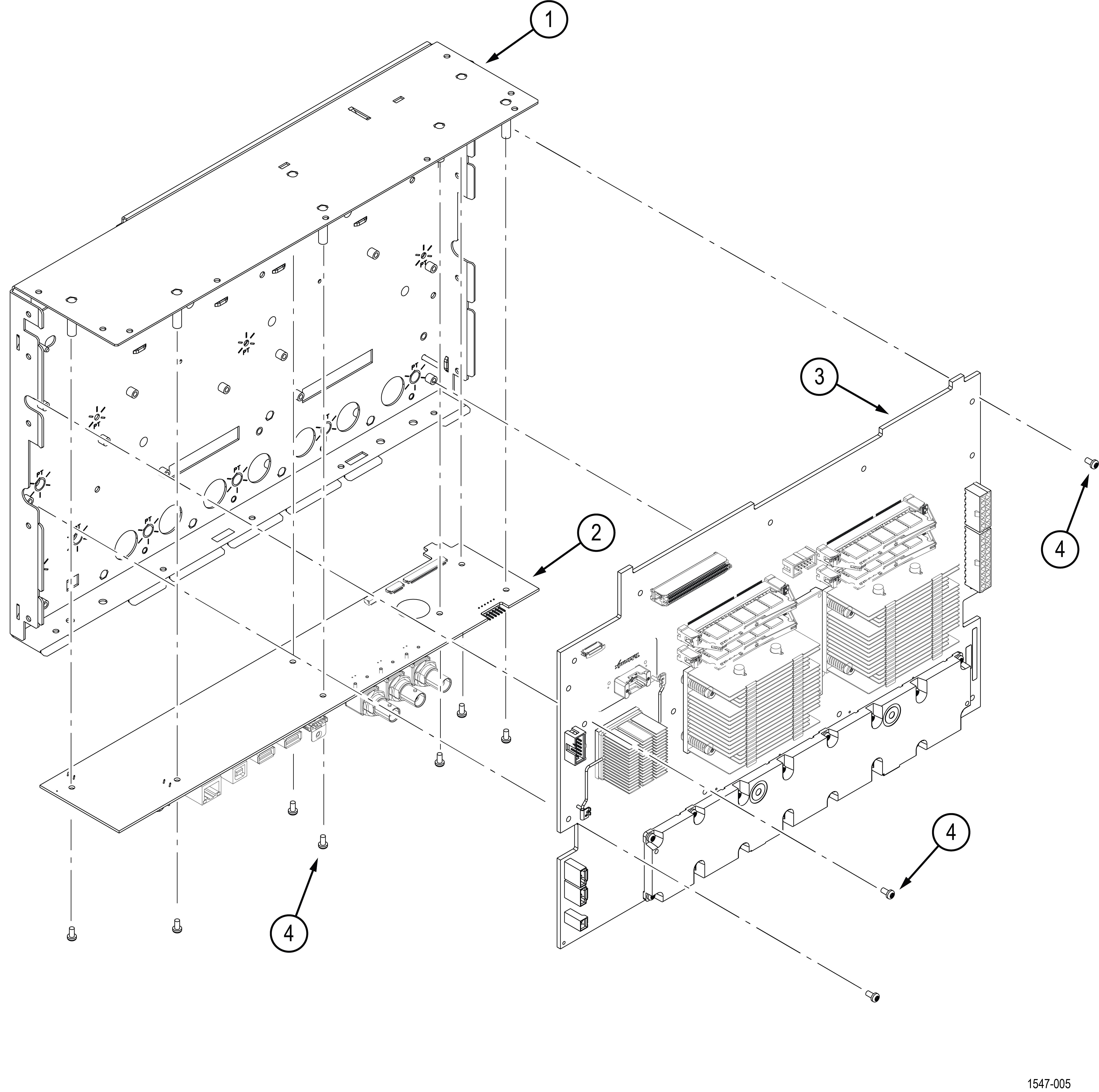
| Note:None of the components listed are user-replaceable. Return the instrument to your nearest Tektronix Service Center to repair or replace any internal components or assemblies in this diagram. |
| Index number | Part number | Serial no. effective | Serial no. discont'd | Qty | Description |
|---|---|---|---|---|---|
| -1 | 441-2901-XX | 1 | CHASSIS, FRONT, ASSEMBLY Return the instrument to Tektronix for service. | ||
| -2 | 878-1383-XX | 1 | CIRCUIT BOARD ASSY, PROCESSOR, 878-1383-XX TESTED WITH PACKAGING Return the instrument to Tektronix for service. | ||
| -3 | 878-1376-XX | 1 | MSO46: CIRCUIT BOARD ASSY, 6CH MAIN, 389-5345-XX, BOMBLD STD Return the instrument to Tektronix for service. | ||
| 878-1593-XX | 1 | MSO44: CIRCUIT BOARD ASSY, 4CH MAIN, 878-1593-XX TESTED WITH PACKAGING Return the instrument to Tektronix for service. | |||
| -4 | 211-1584-XX | 10 | SCREW, MACHINE, M3X0.5X6 MM PAN HEAD, TORX T10 |
Help us improve our technical documentation. Provide feedback on our TekTalk documentation forum.