Introduction
Many electronic test systems use relay switching to connect multiple devices to sources and measurement instruments. In some cases, multiple sources and measuring instruments are connected to a single device. Switching allows automating the testing of multiple devices, thereby reducing error and costs.
Designing the switching for an automated test system demands an understanding of the signals to be switched and the tests to be performed. Test requirements can change frequently, so automated test systems should provide the flexibility needed to handle a variety of signals. Even simple test systems often have diverse and conflicting switching requirements.
The test definition will determine the system configuration and switching needs.Given the versatility that test systems must offer, designing the switching function may be one of the most complex and challenging parts of the overall system design. A basic understanding of relay types and switching configurations is helpful when choosing an appropriate switch system.
Section 1 describes the effects of switching on system performance. Relay types, switching configurations, and switching hardware options are also discussed.
Effects of Switching on System Performance
As a signal travels from its source to its destination, it may encounter various forms of interference or sources of error. Each time the signal passes through a connecting cable or switch point, the signal may be degraded. Careful selection of the switching hardware will maintain the signal integrity and the system accuracy.
Any switching element used in a test system should come as close to the ideal switch as possible. The ideal switch is one that:
- Has zero resistance when closed.
- Has infinite resistance when open.
- Is completely isolated from all other switches in the system.
- Is isolated from the drive control circuit.
- Takes no time to switch.
System designers must recognize, however, that real switches are not ideal, and that the relays themselves are typically mounted on printed circuit boards, which require the use of connectors and cables. The boards are often placed in a main- frame that electronically controls the opening and closing of the relays. Therefore, when calculating the overall system accuracy, the engineer must include not only the effects of the switch itself, but all the switching hardware in the system.
For example, the offset current of the relays and the leakage resistance of the boards, connectors, and cables may degrade the integrity of high impedance applications. Contact potential and contact resistance of the relays can reduce the accuracy of low voltage and low resistance circuits. Switches may reduce the bandwidth of high frequency signals. Crosstalk between channels on the card may limit the low-level performance. The uncertainties that can occur will depend on the type of signals being switched
System speed can also be a critical issue in system accuracy. For example, an erroneous reading will occur if a measurement is taken through a switch before the relay has had sufficient time to settle. Often, it’s necessary to strike a compromise between system speed and accuracy. Factors that affect system speed include the triggering time of the hardware, the relay actuation and settling times, and software overhead.
Given the uncertainties associated with any new system design, switch hardware specifications must be reviewed carefully to make certain they fit the application. Section 3 provides a detailed description of switch card and mainframe specifications. The types of uncertainties that may arise in the system often depend on the type of signal being switched. Section 5 provides an overview of switching by signal type.
Switch Configurations and Conventions
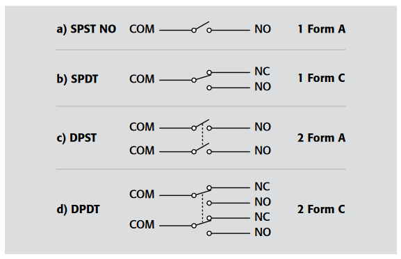
An understanding of how relays are configured is critical to designing a switching system. Three terms are commonly used to describe the configuration of a relay: pole, throw, and form.
Pole refers to the number of common terminals within a given switch. Throw refers to the number of positions in which the switch may be placed to create a signal path or connection. These terms are best described by illustration.
Figure 1-1a shows single-pole, single-throw normally-open switch (SPST NO), while Figure 1-1b shows a single-pole, double-throw (SPDT) switch. One terminal is normally-open (NO) and the other is normally-closed (NC). Depending on the state of the switch, one or the other position is connected to the common terminal (COM). One signal path is broken before the other is connected, which is why this is referred to as a break-before-make configuration
When more than one common terminal is used, the number of poles increases. Figure 1-1c shows a double-pole, single-throw (DPST) switch. Both poles are actuated simultaneously when the relay is energized. In this case, both poles are either always closed or always open. Figure 1-1d shows a double-pole, doublethrow (DPDT) switch.
Contact form, or simply form, is another term that relay manufacturers often use to describe a relay’s contact configuration. “Form A” refers to a single-pole, normally-open switch. “Form B” indicates a single-throw, normally-closed switch, and “Form C” indicates a single-pole, double-throw switch. Virtually any contact configuration can be described using this format. Figure 1-1a, for instance, is a single “Form A” switch, while Figure 1-1d is a dual “Form C” switch.
Switching Topologies
This section describes the various types of switching configurations available: scanner, multiplex, matrix, isolated, and RF switching. The examples provided might provide some guidance when determining which configuration is best for a particular application.
Scanner Switching
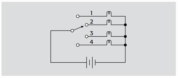
The scan configuration or scanner is the simplest arrangement of relays in a switch system. As shown in Figure 1-2, it can be thought of as a multiple position selector switch.

The scanner is used to connect multiple inputs to a single output in sequential order. Only one relay is closed at any time. In its most basic form, relay closure proceeds from the first channel to the last. Some scanner systems have the capability to skip channels
Figure 1-3 illustrates an example of a scan configuration. In this diagram, the battery is connected to only one lamp at a time, such as in an elevator’s floor indicator system. Another example is a scanner for monitoring temperatures at several locations using one thermometer and multiple sensors. Typical uses of scanner switching include burn-in testing of components, monitoring time and temperature drift in circuits, and acquiring data on system variables such as temperature, pressure, and flow
Multiplex Switching
Like the scan configuration, multiplex switching can be used to connect one instrument to multiple devices (1:N) or multiple instruments to a single device (N:1). However, the multiplex configuration is much more flexible than the scanner. Unlike the scan configuration, multiplex switching permits:
- Multiple simultaneous connections.
- Sequential or non-sequential switch closures
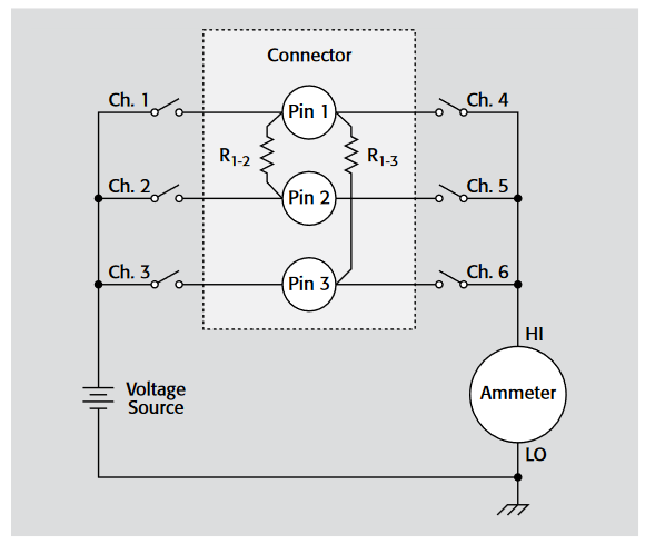
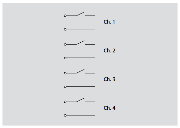
One example of a multiple closure would be to route a single device output to two instruments, such as a voltmeter and a frequency counter. Figure 1-4 illustrates another example of multiplex switching. This diagram shows measuring the insulation resistance between any one pin and all other pins on a multipin connector. To measure the insulation resistance between pin 1 and all other pins (2 and 3), close Chs. 2, 3, and 4. This will connect the ammeter to pin 1 and the voltage source to pins 2 and 3. The insulation resistance is the combination of R1-2 and R1-3 in parallel as shown. Note that in this application, more than one channel is closed simultaneously in non-sequential order. Typical applications of multiplex switching include capacitor leakage, insulation resistance, and contact resistance test systems for multiple devices.
Matrix Switching
The matrix switch configuration is the most versatile because it can connect multiple inputs to multiple outputs. A matrix is useful when connections must be made between several signal sources and a multipin device, such as an integrated circuit or resistor network.
Using a matrix switch card allows connecting any input to any output by closing the switch at the intersection (crosspoint) of a given row and column. The most common terminology to describe the matrix size is M rows by N columns (M×N). For example, a 4×10 matrix switch card, such as the Keithley Model 7012, has four rows and ten columns. Matrix switch cards generally have two or three poles per crosspoint
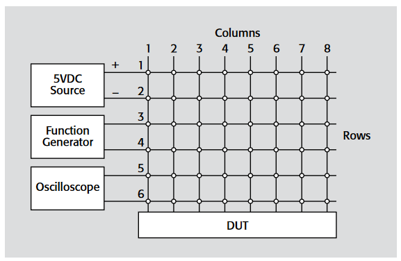
As shown inFigure 1-5, a 5VDC source can be connected to any two terminals of the device under test (DUT). A function generator supplies pulses between another two terminals. Operation of the DUT can be verified by connecting an oscilloscope between yet another two terminals. The DUT pin connections can easily be programmed, so this system will serve to test a variety of parts.
When choosing a matrix card for use with mixed signals, some compromises may be required. For example, if both high frequency and low current signals must be switched, take extra care when reviewing the specifications of the card. The card chosen must have wide bandwidth as well as good isolation and low offset current. A single matrix card may not satisfy both requirements completely, so the user must decide which switched signal is more critical.
In a system with multiple cards, card types should not be mixed if their outputs are connected together. For example, a general-purpose matrix card with its output connected in parallel with a low current matrix card will degrade the performance of the low current card.
| Mainframe | 2700, 2701, 2750 | 7001, 7002 | 7002-HD | 707A, 708A | 3706 |
| Matrix Cards | 7709 | 7012, 7019-C, 7152, 7153 | 7002-HD-MTX1 | 7071, 7071-4, 7072, 7072-HV, 7173-50, 7174A | 3730 |
Matrix Expansion
A large system may require more rows and/or columns than a single card can provide. A matrix can be expanded by joining the rows and/or columns of several cards together. For example, Figure 1-6 shows how the number of columns can be expanded by using two Model 3730 cards to make a 6×32 matrix. Three cards will make a 6×48 matrix, and so on. Depending upon the switch card and mainframe, the rows of the cards may be connected together through the backplane of the mainframe or the rows may be connected externally. The rows of the Model 3730 cards can be connected through the analog backplane of the Series 3700 System Switch/Multimeter. When using multiple matrix cards, check the specifications to determine if the rows can be connected through the backplane or if they must be wired externally.
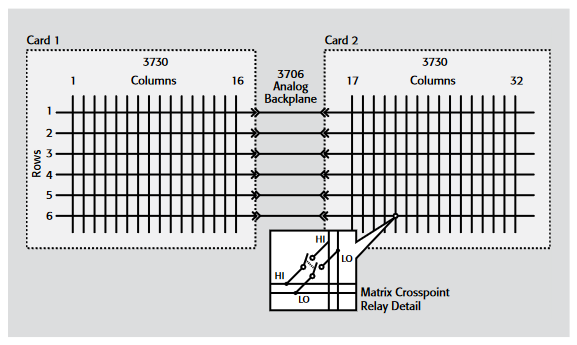
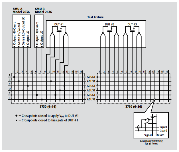
Figure 1-7 shows an example of matrix card rows connected by on-board coaxial jumpers. Up to six Model 3730 matrix cards can be connected in this manner in a Model 3706-S mainframe. With instruments and DUTs both connected to columns, two crosspoints must be closed for each signal path, increasing the safety factor.
The figure shows closed crosspoints for biasing the gate of DUT#1 by one of the SMUs of a Model 2636 System SourceMeter Instrument and applying VDS to DUT#1 by the other SMU in the same Model 2636. The guard pathways of the matrix cards extend driven guard of the SMUs to the DUTs to eliminate the effects of leakage current.
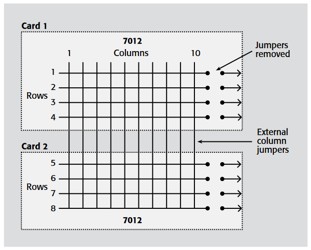
When working with Series 7000 mainframes, to increase the number of rows, the columns of the cards must be connected together externally. For example, Figure 1-8 shows two Model 7012 4×10 cards connected to form an 8×10 twopole matrix
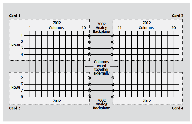
In some cases, both the rows and columns must be expanded. For example, an 8×20 matrix can be configured using four of the 4×10 cards, as in Figure 1-9. If using Model 7012 cards, only the rows are connected through the backplane. The columns must be wired together externally
Isolated Switching
The isolated, or independent, switch configuration consists of individual relays, often with multiple poles, with no connections between relays. Figure 1-10 represents a single isolated relay or actuator. In this diagram, a single-pole normally open relay is controlling the connection of the voltage source to the lamp. This relay connects one input to one output. An isolated relay can have more than one pole and can have normally closed contacts as well as normally open contacts.

Given that the relays are isolated from each other, the terminals of each channel on the switch card are independent from the terminals of the other channels. As shown in Figure 1-11, each isolated Form A relay has two terminals. Two-pole isolated relays would have four terminals (two inputs and two outputs). A Form C isolated relay would have three terminals.
Isolated relays are not connected to any other circuit, so the addition of some external wiring makes them suitable for building very flexible and unique combinations of input/output configurations. Isolated relays are commonly used in power and control applications to open and close different parts of a circuit that are at substantially different voltage levels. Applications for isolated relays include controlling power supplies, turning on motors and annunciator lamps, and actuating pneumatic or hydraulic valves
Keithley Models 7001/7002 family switch cards with isolated relays include the Models 7013, 7037, 7166, 7169A, and 7036. The Model 7705 card for the Models 2700/2701/2750 Integra Multimeter/Data Acquisition/Switch Systems provides 40 isolated relays.
RF Switching: Cascade, Tree, and Matrix Switching
RF (or microwave) signals have switching considerations that differ from those for DC or low frequency AC signals. Some of these considerations include insertion loss, crosstalk, propagation delay, and unterminated stubs. As a result, switching configurations for RF signals are designed to minimize signal losses and maintain a characteristic impedance through the system. Cascade, tree, or matrix switching configurations can be implemented for microwave signal routing.
Cascade
The cascade switching configuration is used to connect one instrument to one of many devices or test points with minimal impedance discontinuity. This is important primarily at frequencies of 10MHz and higher to prevent unwanted signal reflections. Such reflections will create errors in amplitude measurements. Actuation of any one relay disconnects all other devices from the source, as shown in Figure 1-12. In this example, if Channel 1 (Ch. 1) is actuated, a constant impedance path is established from the source to Device 2. All the other devices are isolated from this path. With two cascade switch banks, both source and measure connections can be made to each DUT.
The advantages of the cascade configuration include the fact that there are no unterminated stubs and the configuration is easily expandable. A disadvantage of the cascade configuration is that the signal may pass through more than one switch contact to the device under test, causing higher losses in the signal. The propagation delay will grow with increasing path length.
Tree
The tree switch configuration shown in Figure 1-13 is an alternative to the cascade configuration. When compared to the cascade configuration, the tree technique requires more relays for the same size system, but the isolation between a given path and any unused paths may be somewhat better. This will reduce crosstalk and DC leakage. The tree switch configuration is also used at frequencies greater than 10MHz.

The advantages of the tree configuration include the absence of unterminated stubs and the fact that the channels have similar characteristics. However, multiple relays in a given path mean there will be greater losses
The Model 7016A 50W 2GHz Multiplexer Card, the Model 7017 800MHz Multiplexer Card, and the Model 7038 75W 2.0GHz Multiplexer Card all employ the tree configuration. The Models 7711 and 7712 for the Models 2700/2701/2750 Integra Multimeter/Data Acquisition/Switch Systems provide dual 1×4 configurations.
Matrix
For a matrix, the number of RF relays and cables required to construct a given switching system (and therefore, its cost) is geometrically related to the number of system inputs and outputs. There are three basic types of matrix switch configurations.
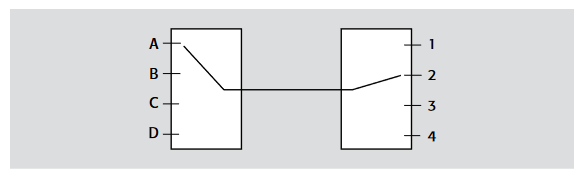
Figures 1-14 and 1-15 are both 4×4 switching matrices. The difference is how many signals can be switched simultaneously. The blocking matrix of Figure 1-14 allows the connection of a single input to any single output. Therefore, only one signal path is active at any given time.
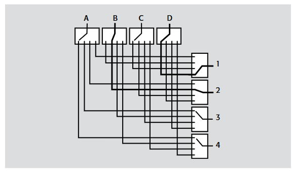
The non-blocking matrix of Figure 1-15 allows simultaneous connection of multiple input/output signal paths, up to the full number of matrix inputs, if desired. With its greater number of relays and cables, this configuration is more flexible and more expensive.
Although it is possible to close multiple paths, this is practical only in DC testing, for example, to apply continuous bias voltage to a number of DUTs. Impedance considerations preclude closing multiple paths in RF and microwave testing.
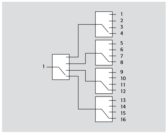
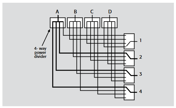
The full or partial access matrix, also referred to as the full or partial fan-out matrix (Figure 1-16), allows simultaneous connection of an input to multiple outputs. This type of matrix requires a power divider at each input and a multiposition switch at the outputs.
The advantages of these configurations include the absence of unterminated stubs, access to all channels, and similar path characteristics. Disadvantages include the need for extensive cabling and the use of many coaxial relays. The System 41 and System 46 RF/Microwave Switch Systems can be built using any of the matrix switch configurations.
Switching Hardware Options
Some of the factors to consider when selecting from the variety of commercial switching hardware available include:
- Types of signals to be routed.
- Switching configuration required (for example, multiplex, matrix, etc.).
- Minimum/maximum number of switch points.
- Variety of switching elements available.
- Physical size.
- Cost.
- Expandability.
- Control bus compatibility (for example, GPIB, RS-232).
Some of the switching hardware options include stand-alone scanner mainframes, measurement instruments with integrated scanners, and plug-in data acquisition boards
Stand-Alone Scanner Mainframes with Switching Cards
Stand-alone scanner mainframes are designed to allow system developers to plug switching cards with relays into slots in the mainframe, which supplies the relay drive current and various controls for the relays. Keithley Models 7001, 7002, 7002-HD, 707A, and 708A are examples of stand-alone mainframes.
This switching hardware option is the most flexible, because of the variety of compatible cards designed for switching various signal types (for example, high voltage, low current). These cards also make it easier to design a system that combines various switching configurations, such as matrix, cascade, tree, etc.
These systems can be expanded easily by adding more cards and/or mainframes and are GPIB programmable.
Instruments with Integrated Switching Capability
A measurement instrument with integrated switching (sometimes referred to as a data acquisition system) provides the convenience of using a single instrument rather than multiple units. With only one instrument involved, the hardware takes up less rack space, is usually more cost-effective, and programming and triggering are less complicated. However, instruments like this may not offer as many switching card options for various signal types, nor as many switch config-urations, as those offered by stand-alone mainframes. These instruments usually have a wider measurement range with higher resolution and better accuracy than plug-in data acquisition boards. Keithley’s Model 2700/2701/2750 Integra Multimeter/Data Acquisition/Switch Systems, the Model 2000/2000-SCAN Scanning Multimeter, and the Model 6517A Electrometer with the Model 6521 Low Current Scanner Card are all examples of this type of instrument.
Plug-In Data Acquisition Boards
Plug-in data acquisition boards are connected to and controlled by a computer, rather than a separate mainframe. PC plug-in cards are a good choice if the application’s accuracy and resolution requirements are lower (<16-bit), if the required sampling rate is high (1kHz and above), or if a card-based form factor is preferable for the overall system design. This type of data acquisition system is software dependent, and the number of channels is limited by the space available in the computer. Some systems have external expansion slots to accommodate more data acquisition boards.
With this approach, the engineer will be designing the entire measurement system. This can be a complex process that includes choosing appropriate signal conditioners, isolation circuitry, filtering, scaling, formatting, etc.
Find more valuable resources at TEK.COM
Copyright © Tektronix. All rights reserved. Tektronix products are covered by U.S. and foreign patents, issued and pending. Information in this publication supersedes that in all previously published material. Specification and price change privileges reserved. TEKTRONIX and TEK are registered trademarks of Tektronix, Inc. All other trade names referenced are the service marks, trademarks or registered trademarks of their respective companies.
No.1716 Rev.0408