
お問い合わせ
ダウンロード
マニュアル、データシート、ソフトウェアなどのダウンロード:
フィードバック
Tektronix Logic Analyzers
TLA7Dx/Ex Digital Storage Oscilloscope Modules
このデータ・シートの製品は、テクトロニクスでは販売終了となっています。
Tektronix Encoreプレミアム再生品を見るbr/>
上記製品のサポートと保証のステータスをチェックする
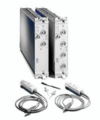
Features & Benefits
- 2/4 Channel Digitizing Oscilloscope Modules with 15 Kb Memory Depth
- Up to 1 GHz Bandwidth Provides High-fidelity Signal Quality Measurements of Digital Signals
- Up to 5 GS/s Sample Rate Provides High Resolution Analog Views of Digital Signals
- Advanced Digital Oscilloscope Triggering Helps Find Elusive Analog Anomalies in Digital Signals
Applications
- Digital Hardware Verification and Debug
- Monitor & Measure Digital Hardware Performance
Breakthrough Solutions for Real-time Digital Systems Analysis
The TLA700 Series offers a range of digitizing oscilloscope modules that provide the acquisition capabilities of the world's best digitizing oscilloscopes, tightly integrated with the TLA700 logic analyzers. The 2 and 4 channel digitizing oscilloscope modules available in the TLA700 Series offer sample rates of up to 5 GS/s and bandwidths of up to 1 GHz, with 15 Kb memory depth per channel at all times.
The digitizing oscilloscope modules offer precise time correlation and flexible cross-triggering with other installed modules. This enables you to see the quality of critical signals time-correlated with the digital signals represented by the logic analyzer modules.
These modules offer the triggering you expect from a Tektronix digital oscilloscope: Pulse Width, Runt, Glitch, Slew Rate, Logic Pattern, Setup-and-Hold Violation, Edge and Timeout.
Characteristics
General
Number of Channels per Module -
TLA7E2: 4 channels.
TLA7D1: 2 channels.
Sample Rate -
TLA7E2: 5 GS/s on all channels.
TLA7D1: 2.5 GS/s on all channels.
Bandwidth (at probe tips) -
TLA7E2:
100 mV to 10 V range: 1 GHz.
50 mV to 99.8 mV range: 900 MHz.
20 mV to 49.8 mV range: 600 MHz.
TLA7D1:
500 MHz on all channels in all ranges.
Memory Depth - 15,000 samples per channel in all modes.
Number of Mainframe Slots Required - 2.
Vertical System
Input Sensitivity Range - 10 mV to 100 V full scale.
Vertical Resolution - 8-Bit (256 levels).
DC Gain Accuracy - ±1.5% of full scale range.
Analog Bandwidth Selections - 20 MHz, 250 MHz, and Full.
Input Coupling - AC, DC or GND.
Input Impedance Selections - 1 MΩ in parallel with 10 pF, or 50 Ω.
AC Coupled Lower Frequency Limit - ≤10 Hz when AC 1 MΩ coupled, ≤200 kHz when AC 50 Ω coupled.
Maximum Input Voltage at Probe Connector - 300 VRMS, but no greater than ±420 Vp (1 MΩ or ground input coupling).
Probe Input Characteristics
Probe Input Interface - TEKPROBE™ probe interface.
Input Loading - Less than 1 pF in parallel with 1 MΩ with either P6243 or P6245.
Usable Input Voltage Range at Probe Tip - P6243 Probe: ±8 V. P6245 Probe: ±18 V.
Acquisition System
Sample Rate Range - 200 ps to 200 ms in 1, 2.5, 5 sequence.
Timebase Accuracy - ±100 ppm over any interval ≥1 ms.
Record Length Range - 512 to 15,000 samples per channel in all modes.
Acquisition Modes - Single-shot, repetitive.
Trigger System
Trigger Modes - Normal, auto.
Trigger Position - Anywhere in the acquired record (pre-fill can be set anywhere from 0% to 100%).
Trigger Types - Edge, pulse width, timeout, glitch, runt, slew rate, logic pattern, setup-and-hold violation.
Trigger Actions - Trigger, trigger all, set signal, arm, immediate, wait for system trigger.
Edge Trigger - Conventional level driven trigger, positive or negative slope, on any channel or external trigger input. Coupling Selections: DC, AC, noise reject, HF reject, LF reject.

Edge trigger.
Pulse Width Trigger - Triggers on
width of positive or negative pulse, either within or not within selectable
time limits; settable from 2 ns to 1 s.
Pulse
Width trigger.
Timeout Trigger - Triggers
when a pulse fails to complete when specified; settable from 2 ns to 1 s.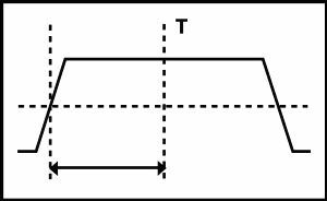
Timeout
trigger.
Glitch Trigger - Triggers on
(or rejects) glitches of positive, negative, or either polarity; settable
from 2 ns to 1 s. Minimum glitch width: 2.0 ns, with 200 ps resolution (2 ns
to 10 ns settings).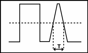
Glitch
trigger.
Runt Pulse Trigger - Triggers
on a pulse that crosses one threshold but fails to cross a second threshold
before crossing the first again; settable from 2 ns to 1 s.
Runt Pulse trigger.
Slew
Rate Trigger - Triggers on pulse edge rates that are either faster or
slower than a set rate, edges can be rising, falling, or either; settable
from 2 ns to 1 s.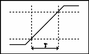
Slew
Rate trigger.
Logic Pattern Trigger - Triggers
when a logical combination (AND, OR) of all the input channels (Hi, Lo, Don't
Care) stays true or false for a specified period of time; settable from 2 ns
to 1 s.
Logic
Pattern trigger.
Setup-and-hold Trigger - Triggers
on violations of both setup time and hold time between clock and data which
are on separate input channels; setup time settable from -100 ns to +100 ns
in 200 ps increments; hold time settable from -1 ns to +102 ns; minimum settable
window of setup time + hold time is 2 ns.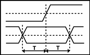
Setup-and-hold trigger.
Safety - CSA C22.2 No. 1010.1, EN61010-1, IEC61010-1, UL 3111-1.
Physical
Physical Characteristics
|
Dimensions |
mm |
in. |
|---|---|---|
|
Weight |
kg |
lb. |
|
Height |
262 |
10.3 |
|
Width |
61 |
2.4 |
|
Depth |
381 |
15 |
|
Net |
2.7 |
5.8 |
|
Shipping |
5.8 |
12.8 |
P6243 Probe Cable Length - 1.3 m (51 in.).
P6245 Probe Cable Length - 1.3 m (51 in.).
Ordering Information
Digitizing Oscilloscope Modules
Includes: Probes, certificate of calibration, and one-year warranty (return to Tektronix), and user manual.
TLA7D1 - 2-Channel DSO module, 500 MHz bandwidth, 2.5 GS/s sample rate, 15 K depth (includes two P6243 1.0 GHz active FET probes, probe calibration adapter and manual).
TLA7E2 - 4-Channel DSO module, 1 GHz bandwidth, 5 GS/s sample rate, 15 K depth (includes four P6245 1.5 GHz active FET probes, probe calibration adapter and manual).
TLA700 Series DSO Module Upgrades
You can install a TLA7Dx/Ex digitizing oscilloscope module into an existing TLA714/715/720/721/7XM mainframe. Please refer to the TLA Family Upgrade Guide for further details.
DSO Module Accessories

P6243 - 1.0 GHz Active FET Probe and accessories, length 1.5 m.
P6245 - 1.5 GHz Active FET Probe and accessories, length 1.5 m.
P6243/P6245 Probe Accessories
|
Part Number |
Description |
|---|---|
|
003-1383-00 |
Compensation box and cover removal tool |
|
003-1433-00 |
Adjustment tool |
|
016-1315-00 |
2 each - 5 colors of cable markers |
|
131-5638-10 |
10 each - solderable probe tips |
|
131-5777-00 |
100 mil square pin ground adapter |
|
196-3410-00 |
Ground lead set includes: |
|
N/A |
2 each - 1 in., 3 in., 6 in. ground leads w/ square pin receptacle; |
|
N/A |
2 each - Y lead adapters |
|
196-3439-00 |
1 in. ground lead |
|
206-0364-00 |
SMT KlipChip, 1 each |
|
214-4227-00 |
Right angle square pin adapter |
|
SF501 |
SureFoot® probe tip adapter, pkg. of 12, yellow, 50 mil pitch |
|
SF502 |
SureFoot probe tip adapter, pkg. of 12, blue, 25 mil/0.65 mm pitch |
|
SF503 |
SureFoot probe tip adapter, pkg. of 12, red, 0.5 mm pitch |
|
SMG50 |
SMT KlipChip grabber tip, 20 each |
|
SMK4 |
Micro KlipChip adapter, 4 each |
|
070-9408-00 |
P6243 Instruction Manual |
|
070-8995-01 |
P6245 Instruction Manual |
TLA Family Service Option Availability
|
|
TLA6XX |
TLA715/721 |
TLA7XM |
TLA7Axx |
TLA7NX/PX/QX |
TLA7PG2 |
TLA7DX/EX |
|---|---|---|---|---|---|---|---|
|
Opt. IN |
|
X |
X |
X |
X |
X |
X |
|
Opt. R3 |
X |
X |
X |
X |
X |
X |
X |
|
Opt. R5 |
X |
X |
X |
X |
X |
X |
X |
|
Opt. S1 |
|
X |
X |
|
|
|
|
|
Opt. S3 |
|
X |
X |
|
|
|
|
|
Opt. C3 |
X |
X |
|
X |
X |
|
X |
|
Opt. C5 |
X |
X |
|
X |
X |
|
X |
|
Opt. D1 |
X |
X |
|
X |
X |
|
X |
|
Opt. D3 |
X |
X |
|
X |
X |
|
X |
|
Opt. D5 |
X |
X |
|
X |
X |
|
X |
Service
Opt. C3 - Calibration Service 3 Years
Opt. C5 - Calibration Service 5 Years
Opt. D1 - Calibration Data Report
Opt. D3 - Calibration Data Report 3 Years (with Option C3)
Opt. D5 - Calibration Data Report 5 Years (with Option C5)
Opt. R3 - Repair Service 3 Years
Opt. R5 - Repair Service 5 Years
Opt. IN - Product Installation Service


