
お問い合わせ
ダウンロード
マニュアル、データシート、ソフトウェアなどのダウンロード:
フィードバック
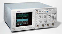
Digital Storage Oscilloscope
TDS714L
このデータ・シートの製品は、テクトロニクスでは販売終了となっています。
Tektronix Encoreプレミアム再生品を見るbr/>
上記製品のサポートと保証のステータスをチェックする
Features & Benefits
- 500-MHz Bandwidth
- 500-MS/s Sample Rate
- Four Channels
- 1% Vertical Accuracy
- 8-Bit Vertical Resolution, Over 11 Bits with Averaging and Over 12 Bits with Hi-Res
- 1-ns Peak Detect
- 1-mV/div to 10-V/div Sensitivity
- Channel Deskew
- Record Lengths to 8-M Points
- Floppy Disk Storage
- Iomega Zip and Zip Plus Drive Compatible
- Advanced Triggering
- 29 Automatic Measurements and Measurement Statistics
- FFT and Advanced Math
- Histograms with Statistics
- Limit Test
- FastFrame™ Time Stamp
- Full GPIB Programmability
- Three-Year Warranty
- CE Marking
Applications
- Power Supply Design and Debug
- Electromechanical Design and Analysis
- Biomedical Product Development
- Automotive Electronics Design and Debug
- Industrial Control
High-Fidelity Signal Acquisition
The high bandwidth (500 MHz) of the TDS714L together with its sample rate (500 MS/s) shows the true signals that other scopes may be missing. The TDS714L provides a wide dynamic range, flat response, fast overdrive recovery, calibrated DC offset, 1-mV/div sensitivity, 1-ns peak detect, and internal calibration.
Easy to Learn and Easy to Use
Extensive user interface design has made the TDS714L truly intuitive to operate. It offers a familiar front-panel layout with dedicated vertical, horizontal, and trigger controls. A graphical user interface with over 200 icons helps facilitate understanding and use of the advanced features. A color monitor helps rapidly distinguish between multiple waveforms and measurements. Online help provides a convenient built-in reference manual.
Powerful and Flexible Triggering
In addition to basic triggering such as edge and pulse-width, the TDS714L has several trigger modes tailored for specific design and debug applications. Logic and pulse triggers, including setup/hold, glitch, slew rate, and time-out triggers, capture hard-to-catch digital design problems. The optional video trigger provides line and field selection for NTSC, PAL, and HDTV standards.
Advanced Performance Features
Color Grading - Displays historical information that has been acquired over time.
Automatic Measurements - Eliminate the need for manually measuring the waveform against the graticule or with cursors. Measurement gating allows the user to select a specific part of the live waveform for measurement. Measurement statistics (min, max, mean, and standard deviation) give additional information about the variations in the measurements over time (for example, worst-case excursions), increasing the confidence in the quality of the measurements.
Waveform Histograms - Allow the examination of the statistical nature of the signal. Horizontal histograms, which are useful for evaluating signal jitter, sample the waveform within a specified region, sort the values into time bins, and plot the accumulated bin values versus time. Vertical histograms, which are useful for evaluating signal noise, sample the waveform within a specified region, sort the values into amplitude bins, and plot the accumulated bin values versus amplitude.
Applications Software Packages
These Java based applications packages reduce the cost, time, and complexity common to many application-specific test procedures. Application-specific capabilities require a hard disk drive (Opt. HD or Opt. 2M).
TDSDDM1 (Disk Drive Measurement Application) provides users with industry standard measurements such as Track Average Amplitude (TAA), 50% Pulse Width (PW50), Non-Linear Transition Shift (NLTS), and Signal-to-Noise Ratio (SNR). This capability gives disk drive designers direct measurements in industry standard terminology.
TDSPWR1 (Power Measurement Application) gives designers interested in power consumption applications the ability to automatically calculate True Power, Apparent Power, Power Factor, Instantaneous Power, and Energy to eliminate manual calculations. In addition, this package provides precompliance current harmonics testing to the EN 61000-3-2 standard.
TDSJIT1 (Jitter and Timing Analysis Application) performs a suite of jitter measurements with unprecedented accuracy on single-shot waveforms. Jitter information can be displayed as statistics, histograms, or profiles.
TDSPSM1 (Processor Specifications Measurement Application) introduces a revolutionary way for making timing measurements by providing statistics on specific data and clock edges that are fully time-correlated. This application also performs automated AC timing measurements on all parameters in single-shot acquisitions.
Complementary Measurement Accessories
Tektronix provides a wide range of measurement accessories optimized for the TDS family. These accessories are designed to operate by using the TEKPROBE™ interface, which provides power and automatic scaling, to complete measurement solutions.
Active Probes were designed to be compatible with the TDS714L. For example, the P6243 is capable of achieving the full 500-MHz bandwidth on a TDS714L while providing low loading.
High-Bandwidth Differential Probes (P6247) enable high-bandwidth differential measurements while maintaining high common-mode rejection.
Current Probes such as the TCP202 and High-Voltage Differential Probes such as the P5205 and P5210 allow safe, high-power measurements. Direct Probe Readouts use information from the probes to display measurements in units of Amps, Volts, and Watts.
Sophisticated Documentation
Save screen displays in a number of standard desktop publishing formats to the internal 3.5-in. MS DOS-compatible floppy disk drive, optional internal hard disk, or external Zip or Zip Plus drive. Import the screen file into word processing applications. Make hard copies directly to monochrome or color printers and plotters connected to the computer network (LAN), GPIB, RS-232, or Centronics ports, or acquire waveforms, screen displays, and scope settings using Tektronix WaveStar™ software running on a PC interfaced to the GPIB port.
Characteristics
TDS714L Electrical Characteristics
Bandwidth - 500 MHz*1
Channels: 4
Max Real-Time Sample Rate -
1 Channel: 500 MS/s
2 Channels: 500 MS/s
3-4 Channels: 500 MS/s
Equivalent-Time Sample Rate: 100 GS/s max
Maximum Record Length -
1 Channel: 250 K (Opt. 2M: 8 M)
2 Channels: 250 K (Opt. 2M: 4 M)
3-4 Channels: 130 K (Opt. 2M: 2 M)
Max Sample Rate Window*2: 16 ms
Display: NuColor™ Display
*1 In 50 ohm mode: 1 mV/div: 450 MHz. Reduce the upper bandwidth frequencies by 2.5 MHz for each °C above 30 °C.
*2 Single-channel operating at full sample rate and maximum record length (Opt. 2M).
TDS714L Vertical System
Sensitivity -
1 mV/div to 10 V/div (1 megohm mode).
1 mV/div to 1 V/div (50 ohm mode).
DC Gain Accuracy - ±1.0% (±0.7% typical).
Effective Bits (typical) -
6.8 (500 MHz at 500 MS/s).
9.7 with hi-res (1 MHz at 10 MS/s).
Vertical Resolution - 8 bit (256 levels on 10.24 divisions), >11 bit with averaging, >12 bit typical with hi-res.
Position Range - ±5 divisions.
Offset Range -
±1 V from 1 mV to 100 mV/div.
±10 V from 101 mV to 1 V/div.
±100 V from 1.01 V to 10 V/div.
Analog Bandwidth Selections - 20 MHz, 250 MHz, full.
Input Coupling - AC, DC, GND.
Input Impedance Selections - 1 megohm in parallel with 10 pF, or 50 ohm (AC and DC coupling).
AC-Coupled Low-Frequency Limit -
≤10 Hz when AC 1 megohm coupled.
≤200 kHz when AC 50 ohm coupled.
Channel Isolation - ≥100:1 at 100 MHz and ≥30:1 at the rated bandwidth.
Max. Input Voltage - 300 V CAT II ±400 V (peak). Derate at 20 dB/decade above 1 MHz. 1 megohm or GND coupled.
TDS714L Timebase System
Time Bases - Main, delayed
Time Base Range - 500 ps to 10 s/div
Time Base Accuracy - ±25 ppm (over any interval ≥1 ms)
Delta Time Measurement Accuracy (typical) - ±[(0.15/sample rate) + (25 ppm × |reading|)]
Trigger Jitter - 8 ps (typical)
Pretrigger Position - 0% to 100% of any record
Delay Between Channels - ≤50 ps (any 2 channels with equal V/div and coupling)
Acquisition Modes
Peak Detect - High-frequency and random glitch capture. Captures glitches of 1 ns using acquisition hardware at all real-time sampling rates.
Sample - Sample data only.
Envelope - Max/min values acquired over one or more acquisitions.
Average - Waveform data from 2 to 10,000 (selectable) is averaged.
Hi-Res - Vertical resolution improvement and noise reduction on low-frequency signal (e.g., 12 bit typical).
FastFrame™ Time Stamp - Acquisition memory size segmentable with trigger rate up to 80,000 per second from 50 to 50,000 points per frame (independent of the number of channels).
Single Sequence - Use RUN/STOP button to capture a single triggered acquisition at a time, which may be automatically saved to NVRAM with Auto-Save.
Trigger System
Triggers - Main and delayed
Main Trigger Modes - Auto, Normal, Single
Delayed Trigger - Delayed by time, events, or events and time
Time Delay Range - 16 ns to 250 s
Events Delay Range - 1 to 10,000,000 events
External Rear Input - ≥1.5 kilohm; Max input voltage is ±20 V (DC + peak AC)
Trigger Types
EDGE (Main and Delayed) -
Conventional level-driven trigger. Positive or negative slope on any channel or rear-panel auxiliary input. Coupling selections: DC, AC, noise reject, HF reject, LF reject.
LOGIC (Main) -
PATTERN: Specifies a logical combination (AND, OR, NAND, NOR) of the four input channels (high, low, don't care). Trigger when pattern stays true or false for a specified time.
STATE: Any logical pattern of channels 1, 2, and 3 plus a clock edge on channel 4. Triggerable on rising or falling clock edge.
SETUP/HOLD: Trigger on violations of both setup time and hold time between clock and data which are on two input channels.
PULSE (Main) -
GLITCH: Trigger on or reject glitches of positive, negative, or either polarity. Minimum glitch width is 1.0 ns (typical), 2 ns (warranted) with 200-ps resolution.
RUNT: Trigger on a pulse that crosses one threshold but fails to cross a second threshold before crossing the first again.
WIDTH: Trigger on width of positive or negative pulse either within or out of selectable time limits (1 ns to 1 s).
SLEW RATE: Trigger on pulse-edge rates that are either faster or slower than a set rate. Edges can be rising, falling, or either.
TIME-OUT: Trigger on an event which remains high, low, or either, for a specified time period, selectable from 1 ns to 1 s, with 200-ps resolution.
VIDEO (Optional) -
Trigger on a particular line of individual, odd/even, or all fields.
Trigger on a specific pixel of a line by using the video trigger with delay by events. Choose positive or negative horizontal sync polarity.
525/NTSC: Choose monochrome or color (studio-quality NTSC) sync formats.
625/PAL: Choose color or monochrome (studio-quality PAL) sync formats.
HDTV: Choose from 1125/60, 1050/60, 1250/50, and 787.5/60 HDTV formats.
Measurement System
Automatic Waveform Measurements -
Period, frequency, +width, -width, rise time, fall time, +duty cycle, -duty cycle, delay, phase, burst width, high, low, max. min, peak-to-peak, amplitude, +overshoot, -overshoot, mean, cycle mean, RMS, cycle RMS, area, cycle area, extinction ratio (ratio, dB, %) and mean optical power. Continuous update of up to four measurements on any combination of waveforms.
Measurement Statistics - Display minimum and maximum or mean and standard deviation on any displayed single-waveform measurement.
Thresholds - Settable in percentage or voltage.
Gating - Any region of the waveform may be isolated for measurement using vertical bars.
Snapshot - Performs all measurements on any one waveform showing results from one instant in time.
Cursor Measurements - Absolute, Delta: Volts, Time, Frequency, and NTSC IRE and line number (with video trigger option).
Cursor Types - Horizontal bars (volts), vertical bars (time); operated independently or in tracking mode.
Waveform Processing
Waveform Functions - Sin(x)/x or linear interpolation, Average, Envelope.
Advanced Waveform Functions - FFT, Integration, Differentiation.
Arithmetic Operators - Add, Subtract, Multiply, Divide, Invert.
Autoset - Single-button, automatic setup on selected input signal for vertical, horizontal, and trigger systems.
Waveform Limit Testing - Compares incoming or math waveform to a reference waveform's upper and lower limits.
Waveform Histograms - Both vertical and horizontal histograms, with periodically updated measurements, allow statistical distributions to be analyzed over any region of the signal.
Zoom Characteristics
The Zoom feature allows waveforms to be expanded or compressed in both vertical and horizontal axes. Allows precise comparison and study of fine waveform detail without affecting ongoing acquisitions. When used with Hi-Res or Average acquisition modes, Zoom provides an effective vertical dynamic range of 1000 divisions or 100 screens.
Dual Window Zoom - Dual graticules simultaneously show selected and zoomed waveforms. Up to two zoom boxes show areas on the selected trace that are being magnified, and the two magnified areas can be overlapped for quick comparison. Color of zoomed trace matches selected trace.
Display Characteristics
Waveform Style - Dots, vectors, variable persistence from 250 ms to 10 s, infinite persistence, and intensified samples.
Color - Standard palettes and user-definable color for waveforms, text, graticules, and cursors. Measurement text and cursor colors matched to waveform. Waveform collision areas highlighted with different color. Statistical waveform distribution shown with color grading through variable persistence.
Color Grading - With variable persistence selected, historical timing information is represented by temperature or spectral color scheme providing "z-axis" information about rapidly-changing waveforms.
Graticules - Full, grid, cross-hair, frame, NTSC, and PAL (with video trigger option).
Format - YT and XY.
Type - 7-in. diagonal, NuColor™ liquid-crystal full color shutter display, 256 color levels.
Resolution - 640 horizontal by 480 vertical displayed pixels (VGA).
Computer Interface
GPIB (IEEE-488.2) Programmability - Full talk/listen modes. Control of all modes, settings, and measurements.
Interface - GPIB standard.
Hard Copy
Printer - HP Thinkjet, Deskjet, Laserjet, Epson, Interleaf, PostScript, TIFF, PCX, BMP, DPU411/412, RLE
Plotter - HPGL
Data - MathCad, spreadsheet formats
Hard-Copy Interface - Centronics and RS-232 (talk only).
Storage
Nonvolatile Waveform Storage - 4 full 130-K records, 2 full 250-K records.
Nonvolatile Storage for Setups - 10 front-panel setups.
Floppy Disk Drive - Store reference waveforms, setups, and image files on 3.5-in. 1.44-MB or 720-K MS DOS-format floppy disk.
Iomega Zip and Zip Plus Drive Compatible - Compatible for waveform and front-panel setup file transfer to Iomega Zip and Zip Plus Drives.
Hard Disk Drive - (Opt. HD, included with Opt. 2M) Store reference waveforms up to 8 M in length, front-panel setups, and image files. Provides Java Run-Time Environment for Application packages.
Power Requirements
Line Voltage Range - 100 to 240 VRMS
Line Frequency - 45 to 440 Hz
Power Consumption - 350 W max
Environmental and Safety
Temperature -
Operating: 0 to +50 °C (floppy not used), +10 to +50 °C (floppy in use)
Nonoperating: -22 to +60 °C
Humidity -
Operating: 20% to 80% RH at ≤33 °C. Derates to 25% RH at +50 °C
Nonoperating: 5% to 90% RH at ≤31 °C. Derates to 20% RH at +60 °C
Altitude -
Operating: 15,000 ft. (hard disk not used), 10,000 ft. (hard disk in use)
Nonoperating: 40,000 ft.
Electromagnetic Compatibility - 89/336/EEC
Safety - UL3111-1, CSA1010.1, EN61010-1, IEC61010-1
Physical Characteristics
|
Dimensions |
mm |
in. |
|---|---|---|
|
Height with feet |
193 |
7.6 |
|
Height without feet |
178 |
7 |
|
Width with handle |
445 |
17.5 |
|
Depth with front cover installed |
434 |
17.1 |
|
Weight |
kg |
lbs. |
|
Net approximately |
14.1 |
31 |
|
Shipping weight approximately |
25.4 |
56 |
-

Product(s) are manufactured in ISO registered facilities. Product(s) complies with IEEE Standard 488.1-1987, RS-232-C, and with Tektronix Standard Codes and Formats. 3GW-23239-0

