
お問い合わせ
ダウンロード
マニュアル、データシート、ソフトウェアなどのダウンロード:
フィードバック
Arbitrary Waveform Generators
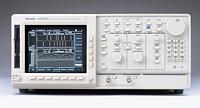
AWG520
このデータ・シートの製品は、テクトロニクスでは販売終了となっています。
Tektronix Encoreプレミアム再生品を見るbr/>
上記製品のサポートと保証のステータスをチェックする
Features & Benefits
- Two Channels with 10-Bit Vertical Resolution
- Independent 10-Channel, 1 GHz Digital Data Generation (Opt. 03)
- Built-in Independent Real-time Noise Generation
- External Clock Input Permits Jitter Insertion and Synchronization
- Supports Direct External Clock and 10 MHz Reference Input
- Unique Real-time Sequencing Links Multiple Waveform Files Creating Waveforms of Nearly Infinite Length
- Built-in Application Generates Jitter, Data Communication and Disk Drive Waveforms
- User Modified Isolation Pulse for Disk Drive Testing
- Built-in 10 GB Hard Drive for Mass Data Storage that can Optionally be made Removable for Secure Applications (using Opt 11)
- Optional 128 MB Flash Disk for ATE Applications (Opt 10)
- Replace Standard Function and Sweep Generators in Wide Range of Applications
Applications
- Communications Design and Test:
- Low Frequency Modulated RF with Components Using AM and FM Modulation
- Digital Information Encoding Using FSK, PSK and QAM (Quadrature Modulation) for Cellular, Fax and Modem Communications
- Optical Communications Design and Test:
- Reflections, Crosstalk and Ground Bounce Simulation
- Pulse Generation:
- Duty Cycle Ranges from 0% to 100% for NRZ Data
- Testing Clock/Gating Width Variations
- Real-world Simulations:
- Corrupt Ideal Waveforms
- Add Jitter to Waveforms
- EMP/EMI and Other System Noise
- Power Supply Noise and Ripple
- Transducer Simulation
AWG520 Solves Communications Physical Layer and Media Storage Design and Test Challenges
The AWG520's unique design combines a graphical editing display with powerful output capabilities to simplify the creation of arbitrary and complex waveforms and enable easy on-screen waveform editing. With the AWG520's many built-in intuitive and powerful features, you can easily develop and edit custom waveforms. Option 03 adds an independent 10–bit-wide digital data port that can be used in conjunction with marker outputs for data generation up to 14–bits wide at up to 1 GHz (14–bits, AWG520). Direct waveform transfer capability makes the AWG520 the perfect complement to selected Tektronix oscilloscopes.
The AWG520 can easily generate telecom signals which complement masks from a digital oscilloscope.
Characteristics
Operating Modes
Continuous - Waveform is iteratively output. If a sequence is defined, the sequence order and repeat functions are applied.
Triggered - Waveform is output only once when an external, internal GPIB/Ethernet or manual trigger is received.
Gated - Waveform begins output when gate is true and resets to beginning when false.
Enhanced - Waveform is output as defined by the sequence.
Arbitrary Waveforms
Waveform Length - 256 to 4,194,048 points in multiples of four.
Sequence Length - 1 to 8,000 steps. Both CH1 and CH2 operate from the same sequence.
Sequence Repeat Counter - 1 to 65,536 or infinite.
Function Generator Waveforms
Operation Mode - Continuous mode only.
Waveform Shape - Sine, Triangle, Square, Ramp, Pulse, or DC.
Frequency - 1.000 Hz to 100.0 MHz.
Amplitude -
Range: 0.020 Vpp to 2 Vpp into 50 Ω.
Resolution: 1 mV.
Offset -
Range: -1.000 V to +1.000 V into 50 Ω.
Resolution: 1 mV.
DC Level - DC waveform only.
Range: -1.000 V to +1.000 V into 50 Ω.
Resolution: 1 mV.
Phase -
Range: -360° to +360°.
Resolution:
1.000 Hz to 100.0 kHz: 0.036° step.
100.01 kHz to 1.000 MHz: 0.36° step.
1.001 MHz to 5.000 MHz: 1.8° step.
5.001 MHz to 10.00 MHz: 3.6° step.
10.001 MHz to 20.00 MHz: 7.2° step.
20.001 MHz to 25.00 MHz: 9° step.
25.001 MHz to 40.00 MHz: 14.4° step.
40.001 MHz to 50.00 MHz: 18° step.
50.001 MHz to 100.0 MHz: 36° step.
Polarity - Normal, Invert.
Duty Cycle -
Range: 0.1% to 99.9%, Pulse waveform only.
Resolution:
1.000 Hz to 1.000 MHz: 0.1% step.
1.001 MHz to 5.000 MHz: 0.5% step.
5.001 MHz to 10.00 MHz: 1% step.
10.01 MHz to 20.00 MHz: 2% step.
20.01 MHz to 25.00 MHz: 2.5% step.
25.001 MHz to 40.00 MHz: 4% step.
40.01 MHz to 50.00 MHz: 5% step.
50.01 MHz to 100.00 MHz: 10% step.
Marker Out -
Marker1 Pulse Width: Hi / Lo: 20% / 80% of Period.
Marker2 Pulse Width:
Hi / Lo: 50% / 50% of Period, except 5.001 MHz to 8.000 MHz.
Hi / Lo: 52% / 48% of Period, at 5.001 MHz to 8.000 MHz.
Marker Level:
Hi Level: 2 V into 50 Ω.
Lo Level: 0V into 50 Ω.
Clock Generator
Sampling Frequency - 50.000000 kHz to 1.0000000 GHz.
Resolution - 8 digits.
Internal Clock - Accuracy: ±1 ppm.
Phase Noise:
At 1 GHz, 10 kHz offset: -80 dBc/Hz.
At 1 GHz, 100 kHz offset: -100 dBc/Hz.
Internal Trigger Generator
Internal Trigger Rate - Range: 1.0 μs to 10.0 s.
Resolution: 3 digits, 0.1 μs minimum.
Accuracy: ±0.1%.
Main Output
Output Signal - Single-ended; CH1 and CH2.
DA Converter - Resolution: 10-Bit.
Differential Non-linearity: ±1 LSB.
Integral Non-linearity: ±1 LSB.
Normal Out - Pulse Response (-1 and 1 waveform data, 0 V offset, Through filter):
Rise time (10 to 90%): Amplitude >1.0 V, ≤2.5 ns; Amplitude ≤1.0 V, ≤1.5 ns.
Fall time (10 to 90%): Amplitude >1.0 V, ≤2.5 ns; Amplitude ≤1.0 V, ≤1.7 ns.
Aberrations (at 500 MHz): Amplitude >1.0 V, ±10%; Amplitude ≤1.0 V, ±7%.
Flatness (after 50 ns from rise/fall edge): ±3%.
Small signal bandwidth (-3 dB, Amplitude 0.5 V): 300 MHz.
Sinewave Characteristics (1 GS/s clock, 32 waveform points, 31.25 MHz signal frequency, 1.0 V amplitude, 0 V offset, Through filter):
Harmonics: ≤-50 dBc, DC to 400 MHz.
Noise: ≤-53 dBc, DC to 400 MHz.
Phase Noise: ≤-90 dbc/Hz at 10 kHz offset.
Filter:
Type: 10, 20, 50, 100 MHz Bessel low-pass.
Rise time (10 to 90%): 10 MHz, 35 ns; 20 MHz, 17 ns; 50 MHz, 7.0 ns; 100 MHz, 3.5 ns.
Delay from trigger: 10 MHz, 77 ns +1 clock; 20 MHz, 57 ns +1 clock; 50 MHz, 45 ns +1 clock; 100 MHz, 42 ns +1 clock; Through, 37 ns +1 clock.
Direct DA Out - Output Voltage: 0.5 Vp-p (with -0.27 V offset) into 50 Ω.
Amplitude Accuracy: 0.5 Vp-p ±10%.
DC Offset Accuracy: -0.27 V ±10% (waveform data = 0).
Pulse Response (-1 and 1 waveform data):
Rise time (10 to 90%): ≤700 ps.
Fall time (10 to 90%): ≤700 ps.
Output Impedance - 50 Ω.
Connector - Front panel BNC.
Channel Output Summary
|
Output Type |
AWG520 |
|---|---|
|
Analog |
2 |
|
Complement |
N/A |
|
Marker |
CH1: M1, M2 CH2: M1, M2 |
|
Digital (Option 03) |
2 Analog (CH2 Analog = D0 to D9, CH1 and CH2 Analog independent.), D0 to D9, 4 Markers |
Auxiliary Outputs
Marker - Number:
AWG520: 4.
Level:
Hi/Lo: -2.0 V to 2.0 V (0.05 Vp-p to 4 Vp-p) into 50 Ω; -4.0 V to 4.0 V (0.1 Vp-p to 8 Vp-p) into 1 MΩ.
Resolution: 0.05 V.
Accuracy: Within ±0.1 V ±5% of setting.
Rise/Fall Time (10 to 90%, typical):
At 1 Vp-p, Hi +0.5 V/Lo -0.5 V: 0.5 ns.
At 2 Vp-p, Hi +1 V/Lo -1 V: 1.0 ns.
At 4 Vp-p, Hi +2 V/Lo -2 V: 2.0 ns.
Variable Delay:
Range: 0 ns to +2 ns.
Resolution: 20 ps.
Marker Skew: 32 ps.
Connector: Rear-panel SMB.
Clock Out - Level: ECL 100 K compatible.
Connector: Front-panel BNC.
Noise - Level:
Range: -145 dBm/Hz to -105 dBm/Hz.
Resolution: 1 dB.
Accuracy: ±2.5 dB at 100 MHz.
Flatness: ±2.5 dB, 1 MHz to 300 MHz (referenced to -105 dBm/Hz at 100 MHz).
Type: Gaussian.
Connector: Front-panel BNC.
Digital Data Out (Opt. 03) - Output Signals: D0 to D9 (10-Bits).
Level:
Hi/Lo: -2.0 V to 2.0 V (0.1 Vp-p to 4 Vp-p) into 50 Ω; -4.0 V to 4.0 V (0.2 Vp-p to 8 Vp-p) into 1 MΩ.
Resolution: 0.1 V.
Accuracy: Within ±0.1 V ±5% of setting.
Rise/Fall Time (10 to 90%) typical:
At 1 Vp-p, Hi +0.5 V/Lo -0.5 V: 0.5 ns.
At 2 Vp-p, Hi +1 V/Lo -1 V: 1.0 ns.
At 4 Vp-p, Hi +2 V/Lo -2 V: 2.0 ns.
Skew Between Data: ≤1 ns, 330 ps typical.
Delay:
Data to marker: 4.4 ns.
Clock to data: 3.7 ns.
Connector: Rear-panel SMB.
Auxiliary Inputs
Trigger In - Impedance: 1 kΩ or 50 Ω.
Polarity: POS or NEG.
Input Voltage Range:
1 kΩ: ±10 V.
50 Ω: ±5 V.
Threshold:
Level: -5.0 V to 5.0 V.
Resolution: 0.1 V.
Accuracy: ±(5% of level + 0.1 V).
Pulse Width (0.2 V amplitude): 10 ns minimum.
Trigger Holdoff: 500 ns maximum.
Delay to Marker: 30 ns +1 clock.
Connector: Front-panel BNC.
Event Trig Input - Number of Events: 4 Bits.
Input Signals: 4 event bits, strobe.
Threshold: TTL level.
Pulse Width: 64 clocks minimum.
Maximum Input: 0 V to +5 V (DC + peak AC).
Delay to Analog Out: ≤384 clock +20 ns.
Impedance 2.2 kΩ, pull-up to +5 V.
Connector: Rear-panel 9-Pin D-sub.
CH1 ADD Input - Input Voltage Range: -1 V to 1 V (DC + peak AC).
Impedance: 50 Ω.
Bandwidth (-3 dB): DC to 200 MHz at 1 Vp-p input.
Amplitude Accuracy: ±5%.
Connector: Front-panel BNC.
Reference 10 MHz Clock IN - Input Voltage Range: 0.2 V to 3.0 Vp-p, ±10 V maximum.
Impedance: 50 Ω, AC coupled.
Frequency Range: 10 MHz ±0.1 MHz.
Connector: Rear-panel BNC.
External Sample Clock In
Input Voltage Range - 0.25 Vp-p to 1 Vp-p.
Maximum Input Voltage Range - ±10 Vmax.
Impedance - 50 Ω, AC coupling.
Frequency Range - 10 MHz to 900 MHz.
Duty Cycle Ratio - 40% to 60%.
Pulse Width - 0.5 ns minimum.
Connector - Rear panel BNC.
Display
Area - 13.2 cm (5.2 in.) horizontal by 9.9 cm (3.9 in.) vertical.
Resolution - 640 horizontal by 480 vertical pixels.
Data Storage
Internal Hard Disk Drive - 10.0 GB (standard).
Floppy Disk Drive - 3.5 in., 1.44 MB.
Option 10 - Substitute flash disk (128 MB) for HDD, add standby switch. (Opt. 10 is best suited for ATE and system usage requiring 7x24 hour operation.)
Option 11 - Substitute Internal Hard Disk Drive with removable 10.0 GB Hard Disk Drive mounted on top of the instrument
Environmental, EMC, Safety
Temperature - Operating: 10 °C to +40 °C.
Nonoperating: -20 °C to +60 °C.
Humidity - Operating: 20 to 80%, noncondensing.
Nonoperating: 5 to 90%, noncondensing.
Altitude - Operating: Up to 4,500 m. (15,000 ft). Maximum operating temperature decreases 1 °C per 300 m above 1.5 km.
Nonoperating: Up to 15,000 m (50,000 ft.).
Vibration (test limits) - Operating: 0.27 GRMS from 5 to 500 Hz, 10 minutes duration.
Nonoperating: 2.28 GRMS from 5 to 500 Hz, 10 minutes duration.
Shock (test limits) - Nonoperating: 294 m/s2 (30 G), half-sine, 11 ms duration.
EMC Compliance - EN50081-1.
EN50082-1.
FCC Part 15, Subchapter B Class A.
AS/NZS 20641/2.
Safety - UL3111-1, CSA1010.1, EN61010-1, IEC61010-1.
Power
Source Power - Line Voltage Range: 100 to 240 VAC.
Line Frequency: 48 to 63 Hz.
Power Consumption - 600 W at 8 A maximum.
Physical Characteristics
|
Dimensions |
mm |
in. |
|---|---|---|
|
Weight |
kg |
lbs. |
|
Height |
178 |
7.0 |
|
Height with Option 11 |
215.5 |
8.48 |
|
Width |
422 |
17.5 |
|
Depth |
560 |
25.8 |
|
Net |
17 |
37.5 |
Warranty - One year parts and labor.
Other
Programmable Interface - GPIB: 24-Pin IEEE488.1 connector.
Ethernet: 10Base-T, RJ-45 connector.
Keyboard Connector - 6-Pin mini-DIN connector.
Ordering Information
AWG520
Programmable Dual-channel Arbitrary Waveform Generator.
Includes: User manual (071-0099-00), Programmer manual (071-0100-00), GPIB programming examples disk (063-2982-00), sample waveform library disk (063-2981-00), AXW100 ArbExpress™ Software Utility CD (063-3763-00 ), performance verification disk (063-2983-00), power cord, fuse (159-0239-00). Please specify power plug when ordering.
Recommended Accessories
Service Manual - Order 071-0101-01.
Protective Cover - Order 200-3696-01.
GPIB Cable - Order 012-0991-01.
50 Ω BNC Cable (36-inch) - Order 012-1341-00.
50 Ω BNC Cable (98-inch) - Order 012-1256-00.
50 Ω SMB Cable - Order 012-1458-00.
50 Ω SMB-to-BNC Cable - Order 012-1459-00.
50 Ω BNC Termination - Order 011-0049-02.
800 MHz BNC Low-pass Filter - Order 015-0660-00.
400 MHz BNC Low-Pass Filter - Order 015-0659-00.
200 MHz BNC Low-Pass Filter - Order 015-0658-00.
100 MHz BNC Low-Pass Filter - Order 015-0657-00.
Rackmount Conversion Kit - Order 016-1675-01.
Keyboard - IBM-compatible 4-Pin mini DIN connector.
Spare Removable Hard Disk Kit - Order 650-4643-00 (Opt 11 Must be installed).
Options
Opt. 03 - CH. 2 10-Bit output up to 1 GHz.
Opt. 10 - Flashdisk (128 MB) and standby switch - removes HDD. (Opt. 10 is best suited for ATE and system usage requiring 7x24 hour operation.)
Opt. 11 - Removable Hard Disk (exclusive to Option 10 and/or Option 3)
Opt. 1R - Rackmount.
Power Plug Options
Opt. A0 - North America Power
Opt. A1 - Universal EURO Power
Opt. A2 - United Kingdom Power
Opt. A3 - Australia Power
Opt. A4 - 240 V, North America Power
Opt. A5 - Switzerland Power
Service
Opt. C3 - Calibration Service 3 Years
Opt. C5 - Calibration Service 5 Years
Opt. D1 - Calibration Data Report
Opt. D3 - Calibration Data Report 3 Years (with Option C3)
Opt. D5 - Calibration Data Report 5 Years (with Option C5)
Opt. R3 - Repair Service 3 Years
Opt. R5 - Repair Service 5 Years
Warranty
One year parts and labor.
-

Product Area Assessed: The planning, design/development and manufacture of electronic Test and Measurement instruments. Product(s) complies with IEEE Standard 488.1-1987, RS-232-C, and with Tektronix Standard Codes and Formats. 76W-11846-5


