연락처
텍트로닉스 담당자와 실시간 상담 6:00am-4:30pm PST에 이용 가능
전화 문의
9:00am-6:00PM KST에 이용 가능
다운로드
매뉴얼, 데이터 시트, 소프트웨어 등을 다운로드할 수 있습니다.
피드백
스위칭 매개 변수 측정을 위한 표준 방법
스위칭 손실을 최소화하는 것은 SiC 및 GaN 장치로 작업하는 전력 장치 엔지니어에게 지속적으로 중요한 과제입니다. 스위칭 매개 변수를 측정하고 Si, SiC, GaN MOSFET 및 IGBT의 동적 동작을 평가하기 위한 표준 테스트 방법은 이중 펄스 테스트(DPT)입니다. 이중 펄스 테스트를 통해 장치 켜기 및 끄기 동안의 에너지 손실과 역복구 매개 변수를 측정할 수 있습니다.
이중 펄스 테스트 및 이점
이중 펄스 테스트의 기초
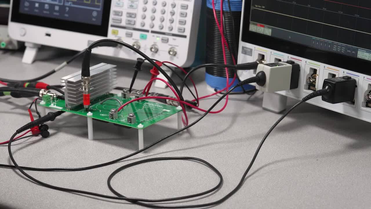
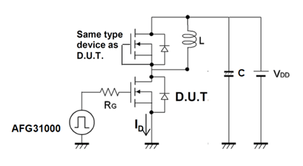
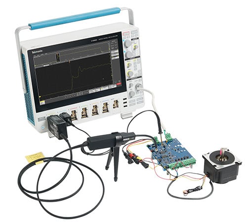
이중 펄스 테스트는 두 개의 장치를 사용하여 수행됩니다. 한 장치는 DUT(테스트 대상 장치)이고 다른 장치는 일반적으로 DUT와 동일한 유형의 장치입니다. "높은" 쪽 장치의 유도성 부하에 유의하십시오. 인덕터는 컨버터 설계에 있을 수 있는 회로 조건을 복제하는 데 사용됩니다. 사용되는 장비는 전압을 공급하는 파워 서플라이(또는 SMU), MOSFET의 게이트를 트리거하여 전류 전도를 시작하도록 펄스를 출력하는 임의 함수 발생기(AFG) 및 결과 파형을 측정하는 오실로스코프입니다.
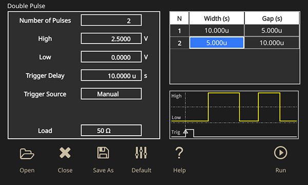
이중 펄스 테스트를 위한 게이트 드라이브 신호를 생성하는 방법
이중 펄스 테스트를 수행하기 위해 게이트 드라이브 신호를 생성하는 가장 쉬운 방법은 임의 파형 발생기(AFG)를 사용하는 것입니다. AFG는 이중 펄스 테스트를 수행하기 위해 게이트 드라이브 신호를 생성하는 데 사용될 수 있습니다. Tektronix AFG31000에는 다양한 폭의 펄스를 생성하기 위한 이중 펄스 테스트 애플리케이션이 내장되어 있습니다.


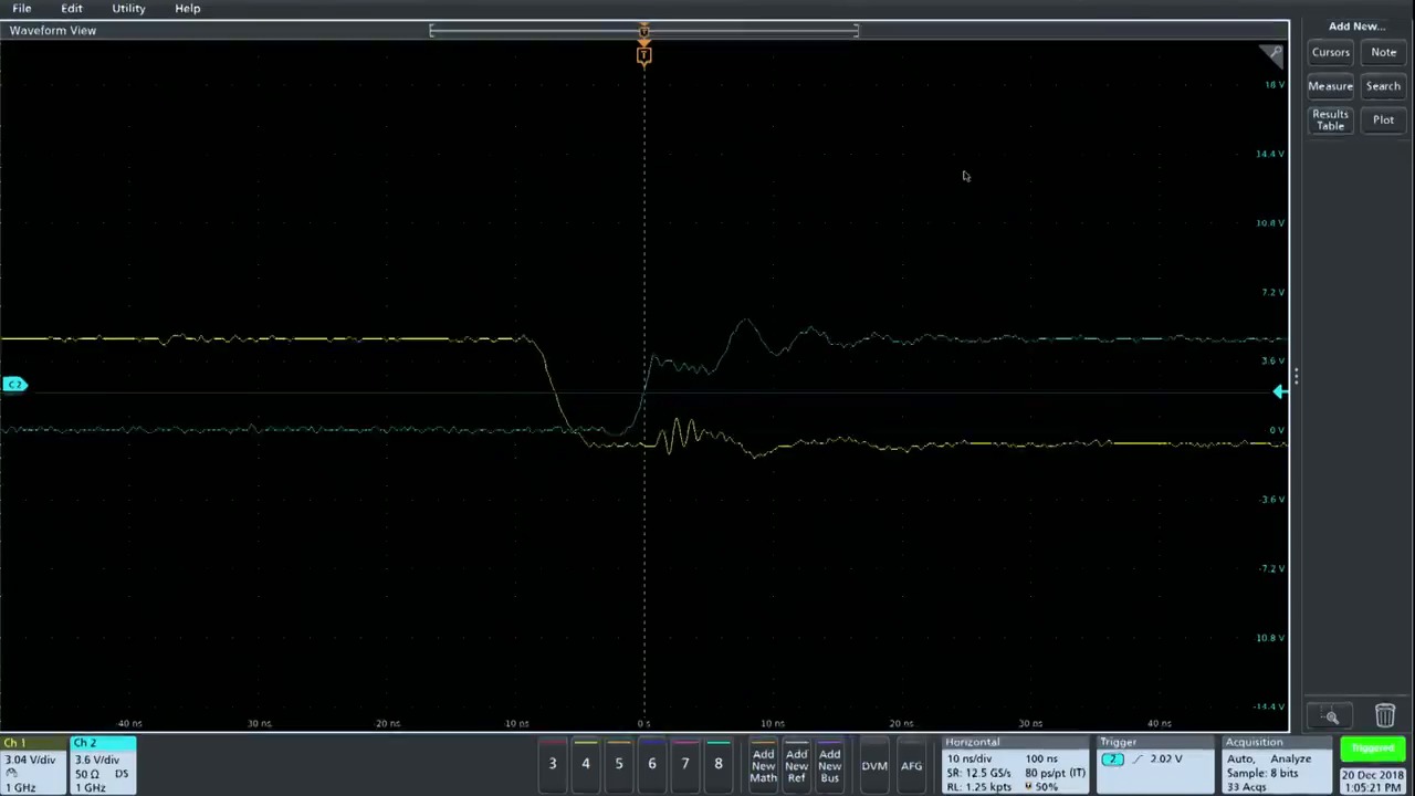
켜기 및 끄기 타이밍과 에너지 손실을 측정하는 방법
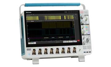
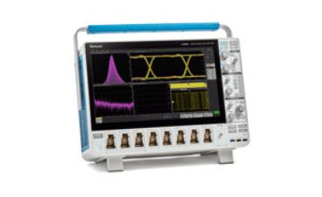
오실로스코프는 이중 펄스 파형을 캡처하는 훌륭한 도구이므로 장치의 켜기 및 끄기 시간 매개 변수를 얻을 수 있습니다. Tektronix 4/5/6 시리즈 B MSO와 광대역 밴드갭 이중 펄스 테스트 애플리케이션 소프트웨어(옵션 WBG-DPT)를 사용하면 매개 변수를 캡처하는 데 필요한 모든 것을 손쉽게 사용할 수 있습니다. WBG-DPT 옵션은 JEDEC 및 IEC 표준에 따라 자동 스위칭, 타이밍 및 다이오드 역복구 측정을 제공합니다.
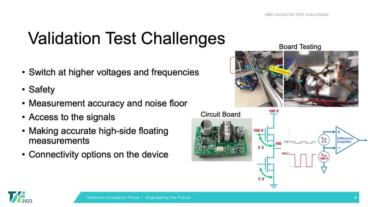
역복구 측정
다이오드의 역복구 시간은 다이오드의 스위칭 속도를 측정하는 척도이므로 컨버터 설계에서 스위칭 손실에 영향을 미칩니다. 역복구 전류는 2차 펄스가 켜지는 동안 발생합니다. 다이어그램에서 볼 수 있듯이 다이오드는 위상 2에서 순방향 상태로 전도됩니다. 낮은 쪽 MOSFET이 다시 켜지면 다이오드가 즉시 역방향 차단 상태로 전환되어야 함에도 짧은 시간 동안 역방향 상태로 전도하게 되는데, 이를 역복구 전류라고 합니다. 이 역복구 전류는 에너지 손실로 변환되어 전력 컨버터의 효율에 직접적인 영향을 미칩니다.

이중 펄스 테스트 회로


-power-electronics-systems/fig-16.png?h=696&iar=0&w=1192)