Introduction
New products must be tested to ensure that they continue to work properly, especially in extreme environments, or to verify the limits of proper working conditions. This may be prescribed per an industry standard or a manufacturer’s in-house rule-of-thumb – in general, many of these standardized processes follow a common pattern. A device under test (DUT) is soaked in a controlled environment over an extended period, and data is taken to observe how the DUT’s performance changes as a result.
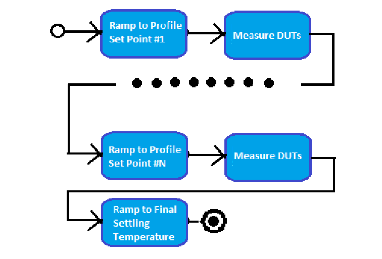
The generalized overall process flow is shown as follows:
A temperature chamber such as the TestEquity Model 115A employs the Watlow F4T Touchscreen Controller to manage environmental conditions for the testing as outlined above, and can stress a DUT at temperatures from as low as -73°C up to +175°C. It can log its environmental conditions over the duration of a programmed profile execution and display this information in graph form on its own 4.3- inch screen. Additionally, this controller provides a series of SCPI commands to promote remote control of the chamber.
The Keithley DAQ6510 Data Acquisition and Multimeter System can monitor the environment until the desired test conditions are achieved before performing a scan and acquiring data. This way, the convenience of using the same unit to both monitor the test chamber and take readings is available to the user. Through the power of Keithley Test Script Processor® (TSP) scripting and instrument communication over a standard Ethernet connection, the DAQ6510 can control the F4T thermal chamber controller.
Instrument Connection Overview
The DAQ6510 provides the user the ability to execute measurement sequences and apply environmental chamber settings all from a single interface. This is achieved by using programming API functions (local to the DAQ6510 embedded processing engine) to make a TCP/IP socket connection to the F4T controller that manages the environmental chamber conditions. This Keithley instrument-level LAN connectivity is referred to as TSP-Net.
TSP-Net allows any Keithley Test Script Processor enabled instrument to directly control up to 32 different Ethernet-enabled devices without the immediate use of a controlling computer. Instead, the instruments are connected to the same network, router, or connected directly to one another via an Ethernet or crossover cable. The controlling instrument uses functions from the Keithley TSP-Net library to transfer control commands to and retrieve responses from a remote instrument, then transfers and formats the data into usable variables that the instrument's processing engine understands (via Lua programming language). This way, the user can send the appropriate commands (typically SCPI) to a subordinate instrument and the controlling/master instrument can receive responses, even if both devices use different command sets. Because the TSP commands used to establish TSP-Net communications format the ASCII data being sent and received, the subordinate device does not need to be TSP compatible. SCPI or any other command set can be used in conjunction with TSP for TSP-Net applications.
Setup
Before running the script that will allow the DAQ6510 to facilitate F4T thermal chamber controller operation, a few steps must be taken or verified beforehand.
1. Scan Hardware Setup – Configuring the DAQ6510 Scan Card
Prior to starting your environmental test, you will need to determine the number of and types of measurements you want to make, whether they be temperature, voltage, or another stimulus. The Connection Log found in Appendix A can be used with the Model 7700 multiplexer (MUX) scan card to help plan and catalog the connections you make for a particular scenario.
It is important to note that the control script will provide you the option to specify the primary point of interest used to start the scan: either a point on the Primary Sensoritself (defined by a MUX channel wired to a transducer located on or near the DUT) or the Process Value reported by the F4T controller.
- Primary Sensor: This point on or near the DUT must be connected to Channel 101 (which is channel 1 of the card in slot 1 of the DAQ6510)
- Process Value: This is the ambient temperature value measured inside the chamber by the F4T controller.
The following steps are an overview of how you would configure your MUX card and install it within the DAQ6510.
a) If your test will rely on a temperature point on the Primary Sensor:
- Install the temperature transducer on channel 1 of the card, which will be placed in slot 1. Route this temperature sensor into to the chamber to monitor its internal temperature.
- Wire additional measurement points of interest to the card’s other channels.
- Insert the switch card(s) into the slot(s) on the rear of the DAQ6510. The card populated with the temperature transducer used to monitor the chamber must be installed in slot 1.
b) If your test will rely on the Process Value of the environmental chamber:
- Wire all measurement points of interest to the card’s channels.
- Insert the switch card(s) into the slot(s) on the rear of the DAQ6510.
NOTE: DO NOT hot swap switch cards. Insert and remove cards only while the DAQ6510 is powered off.
NOTE: For more information on how to make specific Model 77xx multiplexer card connections and install within the DAQ6510, refer to that card’s Instruction Manual found at tek.com.
2. Networking Setup
While computer and instrument networking is not a trivial task, the following details are intended to allow even those users with limited networking experience to establish all necessary connections and modify all necessary instrument settings in order to get the whole system operational.
a) Determine the Network Connection Layout
- Direct Ethernet Connection – In this configuration, the DAQ6510 is directly connected to the F4T controller using an Ethernet crossover cable.

- Connecting Through a Switch – In this configuration, both the DAQ6510 and the F4T controller are connected to an Ethernet switch using crossover cables.
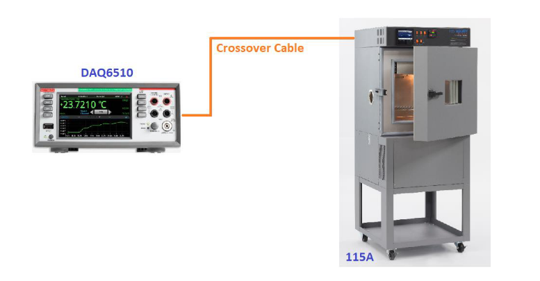
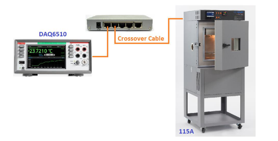
In either scenario, the network configuration setup for both the DAQ6510 and the F4T controller (in the Model 115A) remain the same as detailed below.
Select your desired configuration from the two options above and make the necessary connections.
For simplicity, this section of the documentation will move forward using a direct connection of the instruments and apply Manual Network Configuration settings of both. If you have the option of connecting to your corporate network and would prefer to take advantage of the Automatic Network Configuration setup, refer to Appendix B.
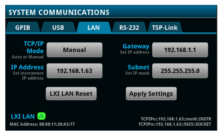
b) Configuring the DAQ6510 Local Area Network Communications Settings
- On the front panel, select the MENU button.
- Under the System column, select Communication.
- In System Communications UI, navigate to the LAN tab.
- Set theTCP/IP Mode field to Manual.
- Set theIP Addressfield to a specific static IP address.
For example: 192.168.1.63. - Set the Subnet field. For example: 255.255.255.0.
- Set the Gateway field. For example: 192.168.1.1. Note: while the Gateway field might not seem necessary for a direct connect setup, the DAQ6510 will not accept the 0.0.0.0 value.
- Select Apply Settings. It may take a few seconds for the DAQ6510 to change to a new network configuration.
- Verify that the LXI LAN indicator is green. If not, make sure the connection is properly set up.
- The above DAQ6510 LAN example settings are merely suggestions and your own manual setup may use otherwise. Use the following table to note your configuration for comparison to the setup of the F4T controller.
IP Address Gateway Subnet
c) Configuring the F4T Controller Local Area Network Communications Settings
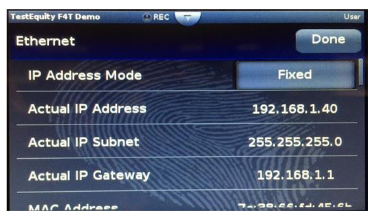
- On the F4T front panel bezel, press the Main Menu icon.
- In the Main Menu, select Settings, then scroll down and select Network, then select Ethernet.
- In the Ethernet menu, touch the button in the IP Address Mode and choose the Fixed option.
- Scroll to the IP Fixed Address entry fields and enter the following:
- Part 1:192
- Part 2:168
- Part 3:1
- Part 4: 40
- Scroll to the IP Fixed Subnet entry fields and enter the following:
- Part 1: 255
- Part 2: 255
- Part 3:255
- Part 4:0
- Scroll to the Fixed IP Gateway entry fields and enter the following:
- Part 1:192
- Part 2:168
- Part 3:1
- Part 4: 1
- When all settings have been entered, touch the Done icon (in the upper right corner of the screen) three times to return to the Home screen
- Cycle power on the F4T Controller. It will take approximately 30 s for the unit to restart.
NOTE: When power is removed from the F4T Controller, the DAQ6510 will report “LAN cable disconnected”. Touch the OK button to accept – this will pass when the controller reboots.
- Press the Main Menu icon again and navigate to the Network settings UI (same as above)
- Verify that all network settings have been applied as expected:
- The above F4T Controller LAN settings are merely suggestions and your own manual setup may use otherwise. Use the following table to note your configuration for comparison to the setup of the DAQ6510.
IP Address Gateway (must match the DAQ6510) Subnet (must match the DAQ6510) - For more information on using the F4T (such as for modifying network settings), please see the documentation provided by the manufacturer.
NOTE: For more detail on specific networking configurations, refer to Appendix B

3. Measurement Scan Setup
Your measurement scan setup will be configured using the DAQ6510 and must be configured prior to running the F4T thermal chamber control script.
- Set the terminal switch to REAR.
- Press the MENU key.
- Under the Channel column, select Scan.
- Press Add Group of Channelsto add and apply measurement functions to the channels the user wants to scan.
- The configuration selected should match the planned MUX card wiring as applied in the section above entitled “Scan Hardware Setup – Configuring the DAQ6510 Scan Card”.
- Be certain that if you plan to use a temperature measurement sensor mounted on or near the DUT, it is configured at the MUX card in slot 1 and on channel 1.
- Accessing the Settings, Scan, and Trigger tabs will allow you to further customize your scan configuration.
For a more comprehensive example on how to build a measurement scan, refer to Appendix C.
NOTE: For more information on how to build scans, refer to the DAQ6510 User Manual found at tek.com.
4. [OPTIONAL] Establishing Temperature Units on the F4T Controller
The F4T Touchscreen Controller is configured by TestEquity for both communication units and display units on the front panel to be in Celsius (°C). Other OEMs may integrate the F4T differently. Additionally, the controller may also be configured by the user to display units in degrees Fahrenheit (°F) via the front panel. Communication units and display units can be set independently.
The F4T controller includes in its SCPI command set a directive that allows an operator to programmatically define the units shared between itself and its remote operator – reported via ethernet – independent of the front panel state. This helps the remote interface ensure proper readback of values as they are expected to be consumed by the controlling program.
For simplicity, the standalone test script program presently only supports °C values issued over the ethernet connection. This script program uses the SCPI command (alluded to above) to specifically configure the F4T controller to report all values over ethernet in °C.
This section first describes how to ensure proper units reported programmatically, and describes how to configure the F4T controller to display Set Point and Process Value readings on its front panel in either °C or °F.
- Configure the F4T Units Reported Over Ethernet
- Ensure proper LAN configuration as defined in the section above entitled, “Configuring the F4T Controller Local Area Network Communications Settings”.
- Using a remote communications tool, issue one of the following commands to the F4T controller to establish units in °C over the ethernet communication channel:
:UNIT:TEMPERATURE C\n - To verify the setting has been applied, issue the following query to the F4T controller:
:UNIT:TEMPERATURE?\n
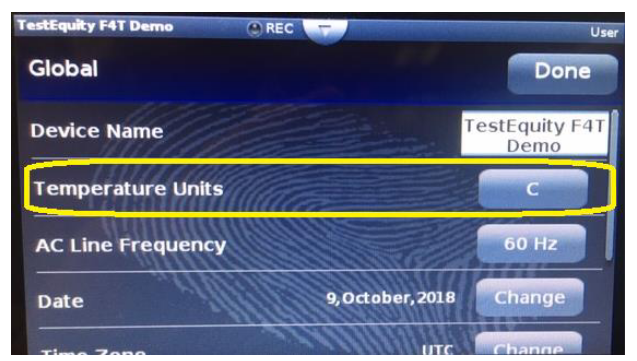
- Configure the F4T Units Shown on the Controller Front Panel
- On the F4T front panel bezel, press theMain Menu icon.
- In the Main Menu, select Settings, then scroll down and select Global
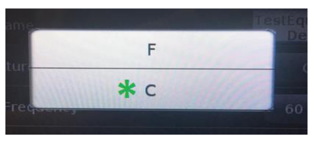
- Touch the button on the right-hand side of the row reading Temperature Units
- From the options provided, select the “C” to set to display values on the front panel in °C.
- On the F4T front panel bezel, press the Home icon.
- After returning to the Home screen, the F4T controller will take approximately 5 seconds to apply all necessary changes.
- On the F4T front panel bezel, press theMain Menu icon.


Loading and Running the Test Script Program
The DAQ6510 has an embedded test script processing engine which allows it execute test sequences (with function calls, decision-making, and communication with other LAN-based instrumentation) local to the instrument in the absence of a controlling PC. This functionality promotes simplified hardware configurations and pairs it with the ease and intuitiveness of the DAQ6510 touchscreen interface.
The script used in this example – entitled F4T_EnvController_DAQ6510 – can to do the following:
- Open a remote sockets-based connection to the F4T controller (from the DAQ6510).
- Define a series of temperature set points (up to 10) for the controller to reach prior to executing the programmed measurement scanning.
- The rate at which a set point is reached can be defined by the user as either immediate (as fast as the chamber can reach setpoint) or as a programmed ramp rate.
- Allow for the applying of a specific soak time for each defined set point. Select a tolerance of how close the measured temperature must be before a soak time is initiated.
- Provide the option for the temperature chamber to return to a user-defined ambient or safe temperature.
- Saving of test data to a USB drive at each of the temperature set points.
NOTE: For simplicity, the standalone test script program presently only supports F4T controllers without Cascade Control (Part Temperature Control).
The F4T_EnvController_DAQ6510 test script can be obtained from a Keithley Instruments Call Center representative or a TestEquity Sales Associate.
The following steps provide an example of how the F4T_EnvController_DAQ6510 test script is used with the DAQ6510 and F4T temperature controller configured as detailed in the previous sections.
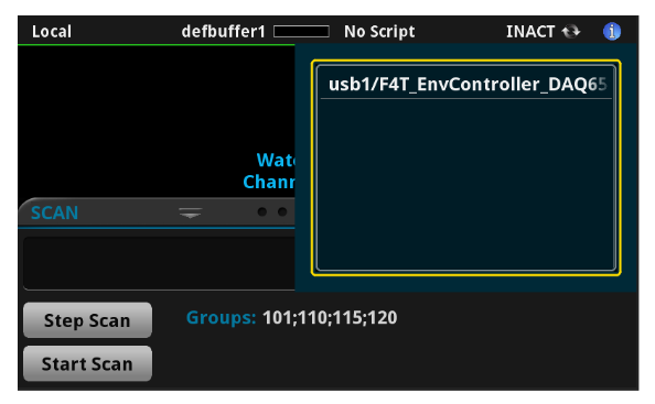
1. Load the F4T_EnvController_DAQ6510 test script on to a USB flash drive.
2. Insert the USB flash drive into the front panel of the DAQ6510. Towards the top of the HOME screen, touch the “No Script” annunciator and select the script F4T_EnvController_DAQ6510 in the resulting menu.
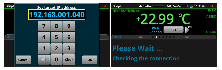
3. The DAQ6510 will open a socket connection to the F4T controller in one of two ways:
- If this is the first time the script is run from the USB drive, you will be prompted to enter the IP address of the F4T controller. Enter the address and press OK. Upon successful connection to the F4T controller, this IP Address is saved to a file on the USB drive for future recall.
- Subsequent runs of the script using the same USB drive and the F4T controller with a matching IP address will automatically extract the IP address from the saved file and use it to make the connection.
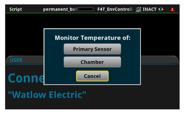
4. The script will prompt the user to select the the temperature measurement device used for checking against the programmed set point(s) and MUX scanning.
- Primary Sensor - This is the transducer on or near the DUT connected to Channel 101 (which is channel 1 of the card in slot 1 of the DAQ6510)
- Chamber – This is the ambient temperature measured inside the chamber by the F4T controller and reported as the Process Value by the controller.
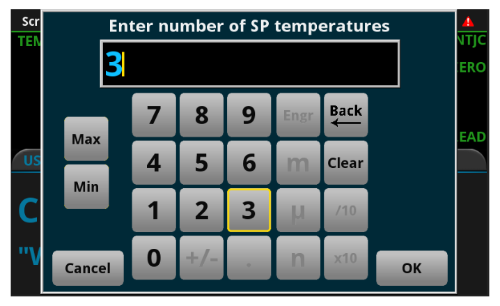
5. You will then define how many temperature set points the chamber will need to achieve over the duration of the test. The maximum is 10; minimum is 1.
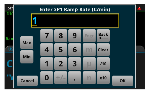
6. You are then presented with the option to apply a custom Ramp Rate to your scan.
NOTE: All chambers have a physical limitation to how fast they can ramp. For example, TestEquity Model 115A is capable of cooling from +85°C to -40°C in 45 minutes, or an AVERAGE of 2.8°C/minute. This is specified with an instantaneous set point change. If you program the chamber for 30°C/minute it will still cool at its maximum achievable rate of 2.8°C/minute. Conversely, if you enter a ramp rate of 2.8°C/minute the chamber will not likely achieve 2.8°C/minute towards the end of the ramp. The maximum published ramp rate is AVERAGE, not linear. It will cool faster in the beginning and slower towards the end. However, if you enter a ramp rate of 1°C/minute, it WILL follow that ramp because that rate is significantly slower than the “full throttle” achievable ramp rate.
- Selecting No indicates that the chamber will go to each set point temperature immediately,as fast as it possibly can.
- Selecting Yes will enable an additional dialog for the remaining set point step attributes entry. You will be able to define the specific Ramp Rate per set point in degrees per minute (°C/min). The maximum is 30°C/min; minimum is1°C/min.

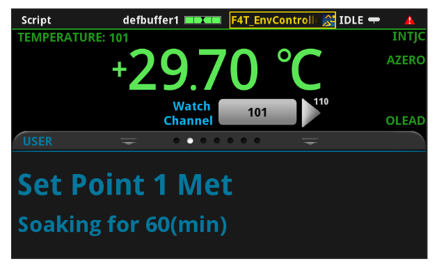
7. Next, you will define the Temperature and Soak Time for each Set Point.
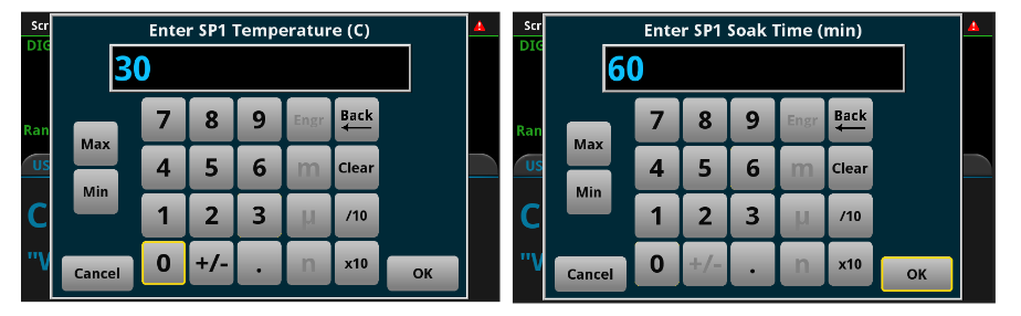
If you chose to also apply a Ramp Rate, a dialog will be provided for you to enter this as well.
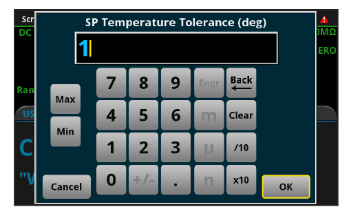
8. You will be presented with the option to apply a tolerance around your target set points. This helps to account for temperatures which may near a particular set point but not be an exact match. Example: Attempting to go to 30°C and the temperature reads 29.8°C. This may be okay for the chamber, but the test program may continue indefinitely because it is looking for a precise level.
Adding the tolerance provides the extra leeway needed and helps progress the testing. The maximum is 5°C; the minimum is 0°C.
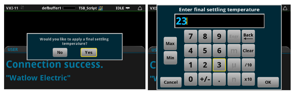
9. You will then be provided the option of applying a final settling temperature. This is especially important for scenarios when the last temperature of your test is at an extreme level (for example, 100°C), and you want to ensure that the operator does not interact with either the DUT or the internals of the environmental chamber.
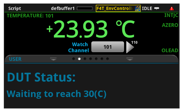
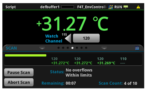
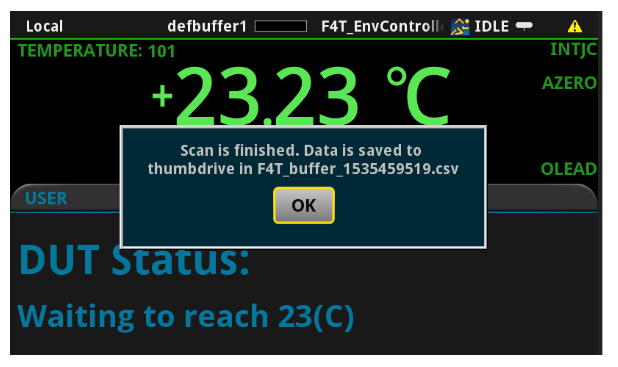
10. The testing will start and provide notifications to the user with respect to test status. You will be provided indications of the temperature change process; the soak time in process; and the scanning process as each becomes active for each of the defined Set Points. Finally, you will receive notice of the test chamber changing to the final settling temperature (if one was applied). A dialog will be presented to you indicating the end of the test and the name of the *.csv file holding the test data saved to the USB thumb drive.
Troubleshooting Information
In the event of errors in the setup, the F4T_EnvController_DAQ6510 test script program contains some diagnostic provisions, which presents messages to the operator on the front panel of the DAQ6510.The messages are listed as follows with short descriptions of meanings and corrective measures.
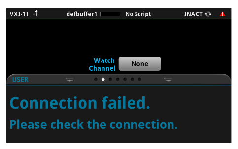
This message indicates a failure of the DAQ6510 to make a LAN connection to the F4T controller. Check the following:
- Ethernet cable connections at the DAQ6510, F4T, or the Ethernet switch (if one is used).
- The IP address entered by the operator or saved on the USB flash drive does not match the controller.
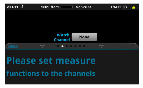
This message indicates that no measurement scan has been configured or established. Refer to the section above – Measurement Scan Setup – to correct.
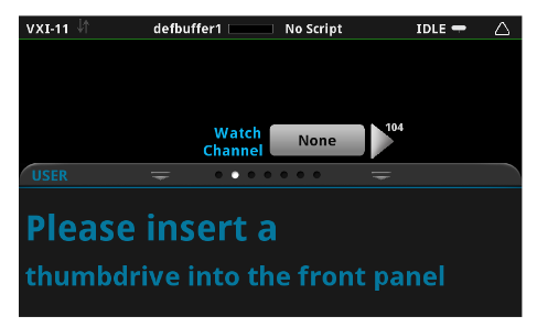
This message indicates that no USB flash drive has been inserted into the front port on the DAQ6510.
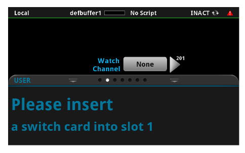
This message indicates that there is a significant hardware setup issue. A multiplexing scan card (such as the Model 7700) is either missing or not properly seated in Slot 1 of the DAQ6510.
The measurement scan card must be properly configured – see Measurement Scan Setup – and be installed in the DAQ6510. Refer to the scan card operator’s guide for a more detailed information on proper installation and removal procedure.
Conclusion
The Keithley DAQ6510 Data Acquisition and Multimeter System can monitor the environment within a test chamber (such as the TestEquity 115A), take readings, and with TSP scripting and instrument communication via TSP-Net, control the test chamber. This functionality applies the ease and intuitiveness of the DAQ6510 touch interface to a F4T thermal chamber controller, including the ability to control the chamber through easy-to-navigate GUIs. The method detailed in this document for thermal chamber control and data acquisition allows for simple and straightforward operation. Because the same unit is being used for both chamber control and data acquisition, those unfamiliar with these devices only need to learn how to operate a single instrument as opposed to an entire environmental testing setup.