

Свяжитесь с нами
Живой чат с представителями Tektronix. С 9:00 до 17:00 CET
Позвоните нам
С 9:00 до 17:00 CET
Загрузить
Загрузить руководства, технические описания, программное обеспечение и т. д.:
Обратная связь
IsoVu Isolated Current Probes
TICP100, TICP050, TICP025 Datasheet
Дополнительные сведения
- IsoVu™ Isolated Current Probes
- Поддержка приборов
- Explore more Пробники и аксессуары models
Читать на веб-сайте:
Overview
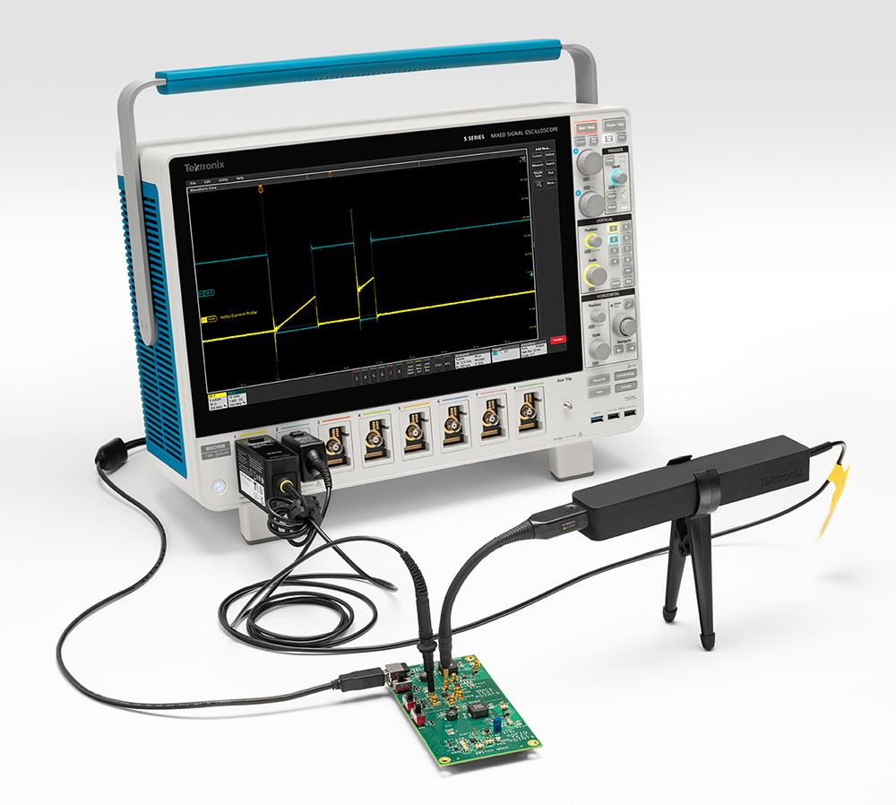
The IsoVu™ isolated current probes deliver exceptional bandwidth, noise rejection, accuracy, and ease of use for making current measurements.
Complete galvanic isolation eliminates ground loops and enables very high common mode rejection. In a 1X configuration, the probe's 50 Ω input offers extremely low noise of less than 4.7 nV/√Hz, ideal for making accurate measurements on shunts. The probes offer a variety of attenuation tips to extend the differential voltage range. Depending upon the shunt used, the probes can perform current measurements from microamperes (µA) for low-power mobile designs to hundreds of amperes for industrial and mobility systems.
Key performance specifications and features
Galvanic isolation between probe tip and the oscilloscope
Available in three bandwidths: 1 GHz, 500 MHz, and 250 MHz
Wide current measurement range determined by the shunt used with 1X, 10X or 100X probe tips
Noise <4.70 nV / √Hz (<21 μV
RMS at 20 MHz)Up to 90 dB CMRR at 1 MHz
Maximum common mode voltage: 1800
V; For use in a Pollution Degree 1 environment; transient level not to exceed 5 kV pk 1.5% DC gain accuracy
Compatible with the 4, 5, and 6 Series MSO instruments, including the latest B models
TekVPI™ interface enables control and probe configuration from the oscilloscope front panel or programming interface
Optional tips to measure currents in environmental chambers from -40ºC to +125ºC
Key applications
Current shunt measurements
Half/full bridge designs using SiC or GaN, FETs, or IGBTs
Double pulse testing (DPT)
Floating gate measurements
Power converter designs
Switching power supply designs
Steady state, sleep, and wake-up state current monitoring
Tips expand measurement ranges, minimize hassle, and reduce noise
The IsoVu isolated current probes are well-suited for both low current and high current measurements that are challenging or impossible with sensor-based clamp-on oscilloscope probes. With three different attenuation tips, you can easily measure a wide range of currents based on the shunt resistance and its power rating.
The probes are designed to provide high-performance current measurements while offering convenient connectivity. Tips are equipped with MMCX and SMA connectors to ensure proper grounding and shielding, which is crucial for minimizing noise, ground loops, and ensuring accurate current measurements. These tips enable direct connection to most commercially available shunts, but you can also use appropriate adapters to interface the tips with their shunts.
The probe tips connect to the probe body with a unique reversible IsoConnect™ interface, allowing you to snap-fit the tips without worrying about orientation. Designed for flexibility, the probe tips have a small bend radius, facilitating connection in tight spaces. The standard probe includes a tripod adapter and a bipod for convenient placement and positioning in the test setup.
Current shunt measurements
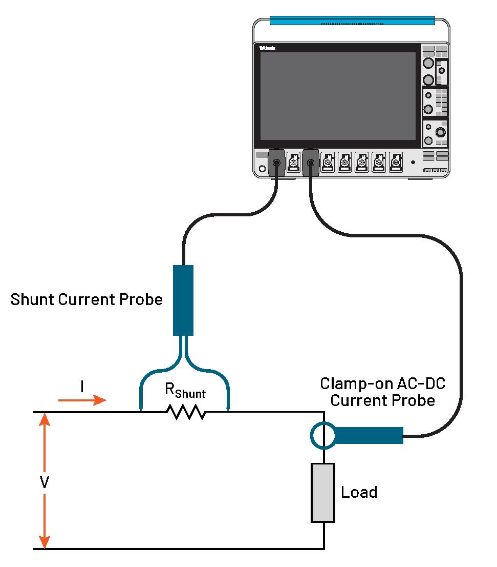
There are two methods to measure current in test systems. The first method involves sensing the fields around the electrical conductors and converting them into signals that represent the current. This method is used by most clamp-on style current probes, or Rogowski coils. The second method involves measuring currents using Ohm’s law. One can measure current by measuring the voltage drop across a precision shunt resistor, which is the method used by the IsoVu isolated current probes.
Current shunts, or current viewing resistors (CVRs), typically have a wide frequency response, accurately measuring both AC and DC currents across a broad spectrum of frequencies. Their compact size allows for easy integration into existing circuitry with minimal space requirements. Although shunt resistors must be designed into a PCB and result in voltage drop, they offer some key advantages compared to sensor-based current measurements, including high accuracy, minimal distortion, and low interference.
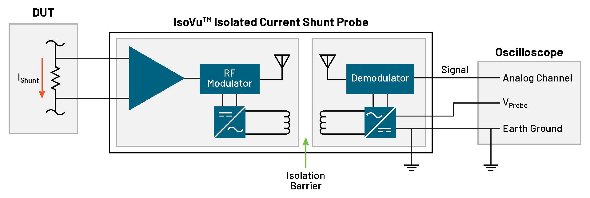
Isolation enables floating measurements and exceptionally low noise
The IsoVu isolated current probes enable you to make more accurate dynamic current measurements on your oscilloscope, outside traditional limits.
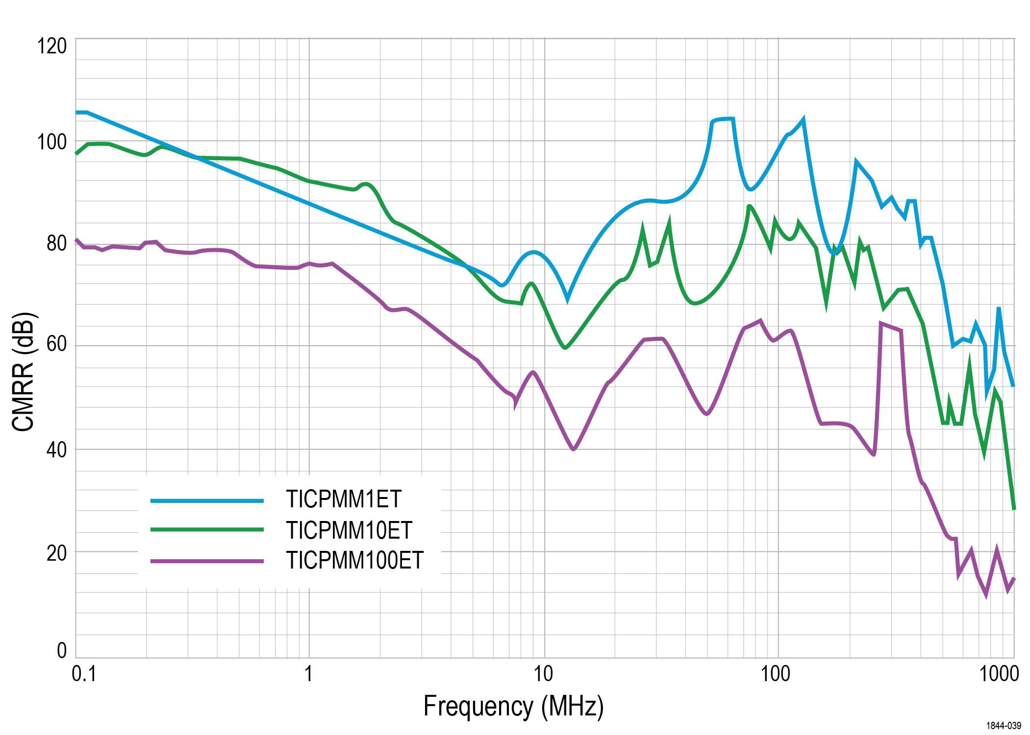
Unlike transformer, Rogowski, or Hall effect current probes, IsoVu isolated current probes enable measurements from DC to hundreds of MHz when paired with high-performance shunts or CVRs. Complete RF isolation between the probe tip and the oscilloscope eliminates ground loops and helps deliver extraordinary common mode rejection (CMRR) up to 90
Test beyond ambient temperature with extreme temperature tips
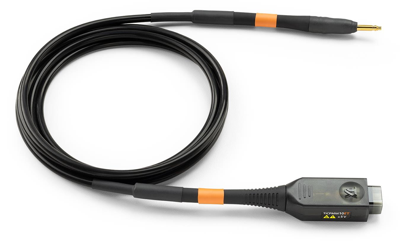
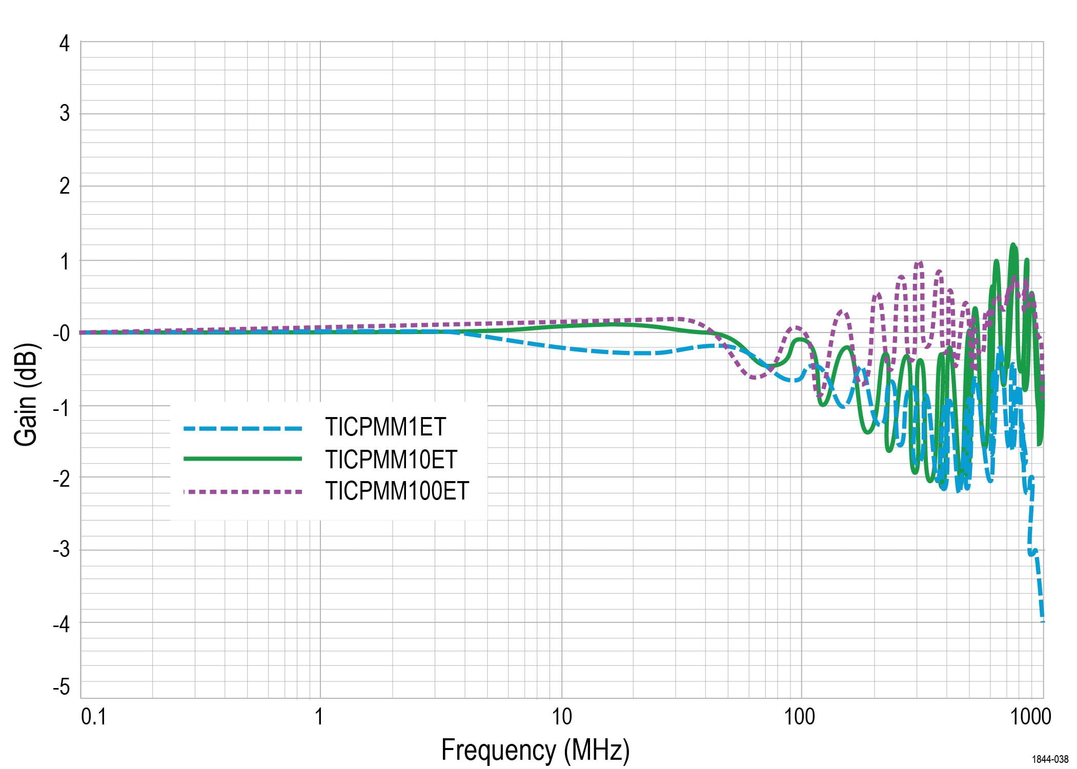
The extreme temperature (ET) tips enable current measurements across a wide temperature range from -40°C to +125°C. Optional six-foot tip cables provide convenient connectivity between a DUT positioned inside a temperature chamber and a Tektronix oscilloscope and isolated current probe located outside the chamber. Available in three attenuation configurations, they deliver exceptional bandwidth performance up to 700 MHz.
Measuring high-fidelity currents in high power systems
The IsoVu isolated current probes provide the bandwidth you need to accurately see the fast risetimes of wide bandgap (WBG) switching devices. This enables you to accurately measure dynamic currents in high-power SiC and GaN power converters. They complement the groundbreaking IsoVu isolated voltage probes and represent a similar isolation breakthrough for current measurements. The isolation eliminates ground loops and enables accurate measurements of high-side drain currents (Ids).
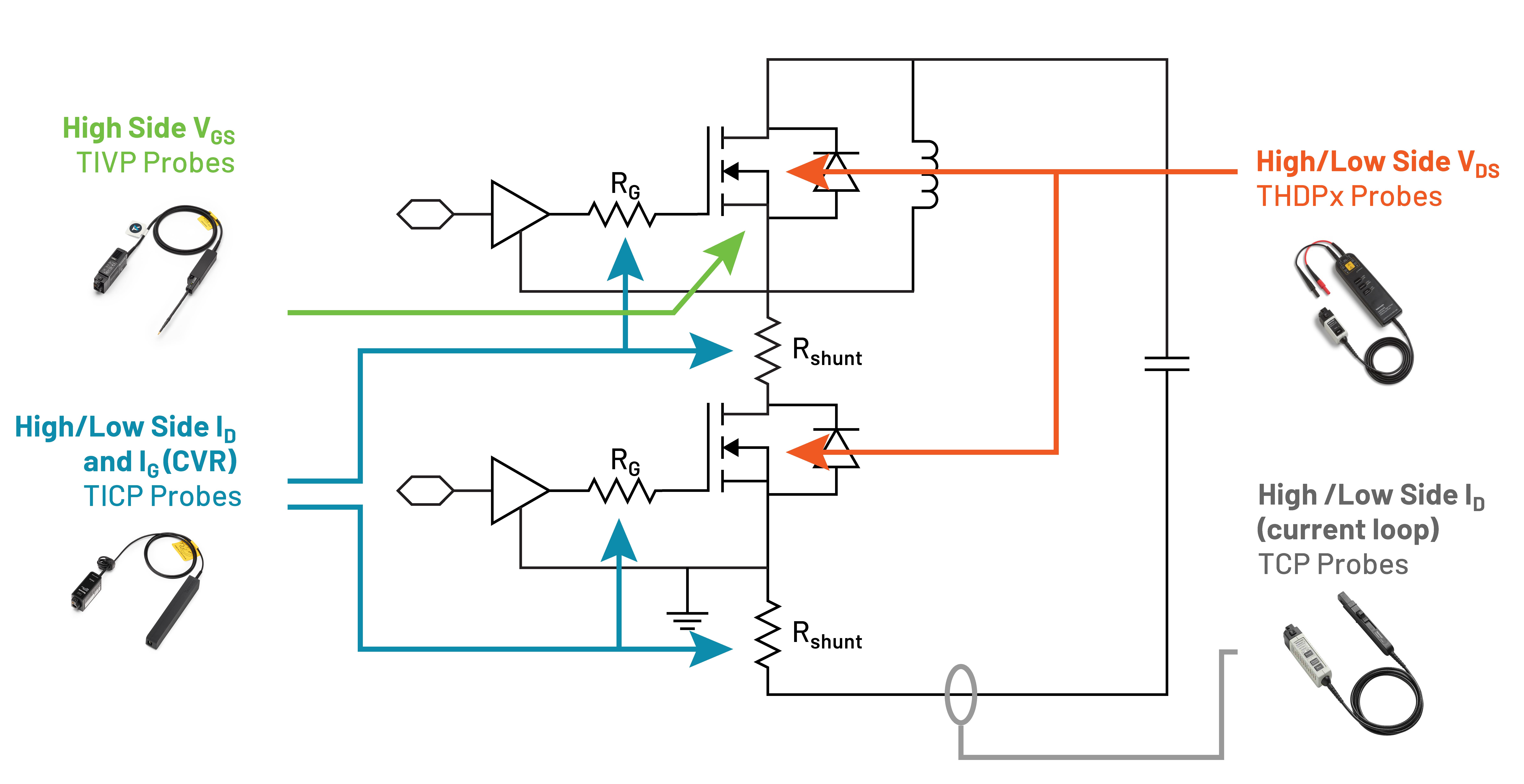
Measuring low currents in low power systems
The IsoVu isolated current probes have the bandwidth to measure current consumption during specific system activities and transitions from sleep to active states. The low-noise architecture is critical for accurately measuring low currents across the shunts. The common mode voltage rating of these probes is higher than most differential probes, enabling current shunt measurements on higher voltage power rails. When paired with the low-noise of the 6 Series MSO, the overall system offers low-noise performance to efficiently measure rail currents.
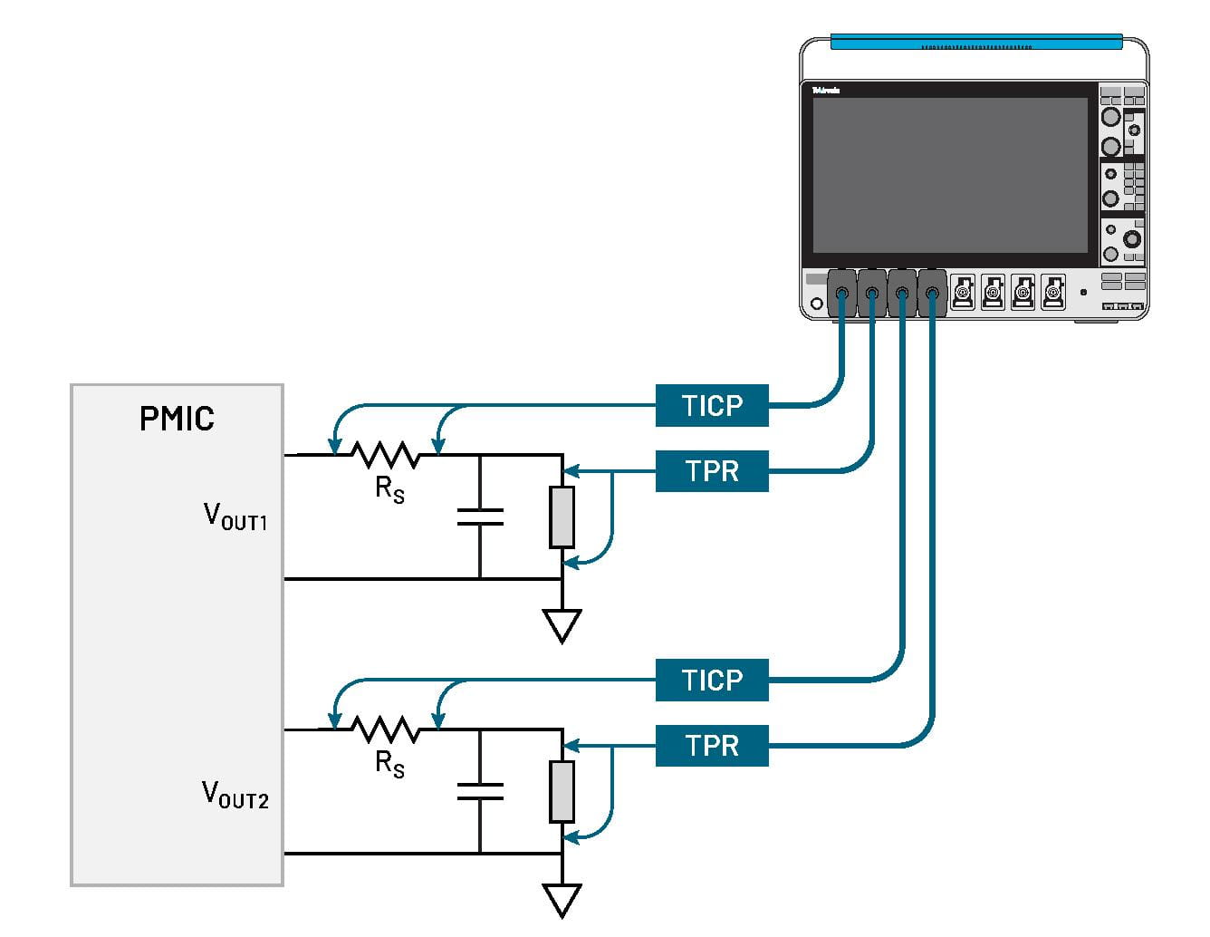
Measuring currents with the wideband shunts
Most commercial current shunts operate at low-bandwidths in the range of a few tens of Megahertz at best. Beyond this bandwidth range, their parasitic inductance effects kicks in, effectively impacting the current measurements and rendering them less useful for accurate measurements.
Wideband shunts for IsoVu™ isolated current probes provide industry-leading current measurements with bandwidths up to 250 MHz, that’s over five times the bandwidth of most commercially available shunts, along with a smooth roll-off behavior, high common-mode rejection, and low-noise.
In addition to the frequency compensation, there is also on-board temperature compensation that keeps the gain flat over the entire operating temperature range. The wideband shunts act as the first line of defense against voltage spikes and over-current. Integrated fuses, spark gaps, and isolation work together to safeguard the equipment in challenging test conditions.
These plug-and-play smart shunts integrate with Tektronix oscilloscopes for current measurements—auto-configuring the units, and vertical scale, ensuring the measurements are performed at minimal noise levels. They connect to the DUT using industry standard square pins.
Combined with a Tektronix oscilloscope, software, and isolated current probes, these innovative wideband shunts enable precise characterization of standby and operating currents in embedded designs, high-performance computing systems, and any application that requires precision high-bandwidth current measurements.
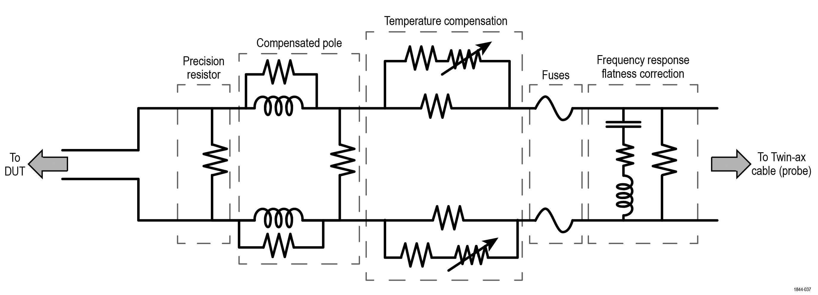
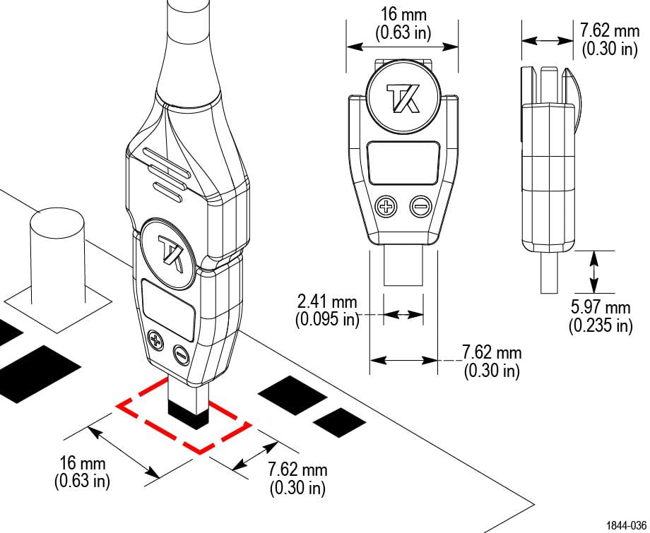
Specifications
All specifications are typical and apply to all models unless noted otherwise.
Probe and tip overview
Characteristic | TICP100 | TICP050 | TICP025 |
|---|---|---|---|
Bandwidth | 1 GHz | 500 MHz | 250 MHz |
Rise time | 400 ps | 700 ps | 1.4 ns |
DC gain accuracy | ±1.5% | ||
Maximum common mode voltage | |||
RMS noise spectral density | 4.70 nV / √Hz (<21 μV | ||
Probe cable length | 2 meters | ||
Characteristic | TICS0005 | TICS0050 | TICS0500 | TICS5000 |
|---|---|---|---|---|
Resistance | 5 mΩ | 50 mΩ | 500 mΩ | 5 Ω |
Bandwidth | 250 MHz | 250 MHz | 250 MHz | 250 MHz |
Rise time | 1.6 ns | 1.6 ns | 1.6 ns | 1.6 ns |
Maximum pulse current (derates based on current pulse width. Refer to pulsed current curve graph) | 200 A | 20 A | 2 A | 200 mA |
Maximum current (A DC) | 12 A | 4.5 A | 1.4 A | 200 mA |
Minimum current (A) equals two times the noise floor at full bandwidth | 30 mA | 3 mA | 300 μA | 30 μA |
Noise Floor (A RMS) at full bandwidth | 15 mA | 1.5 mA | 150 μA | 15 μA |
Dynamic range | ±100 A | ±10 A | ±1 A | ±0.1 A |
Power rating | 0.69 | 1.0 | ||
DC gain accuracy | <2% | |||
Insertion inductance | 2 nH to 3 nH for square pins with jumper | |||
4 nH to 5 nH for square pins with shunt | ||||
9 nH to 10 nH for twisted pair accessory with shunt | ||||
Twin-ax cable length | 229 mm (9 in.) | |||
The built-in fuses have a maximum interruptible voltage rating of 400 V; above this potential, arcing can occur across the open fuse element, allowing current to continue flowing. | ||||
Input voltage range, input impedance
Probe tips | Differential input voltage range | Offset range | Maximum measurable input voltage (Vpk) | Maximum non-destructive differential voltage | Input impedance |
|---|---|---|---|---|---|
TICPSMA | ±0.5 V | ±0.5 V | 0.65 V | ±3 V; 3 V | 50 Ω || N.A. |
TICPMM1/TICPMM1ET | ±0.5 V | ±0.5 V | 0.65 V | ±3 V; 3 V | 50 Ω || N.A. |
TICPMM10/TICPMM10ET | ±5 V | ±5 V | 6.5 V | ±15 V; 15 V | 500 Ω || <3 pF |
TICPMM100/TICPMM100ET | ±50 V | ±50 V | 50 V | ±60 V; 60 V | 5000 Ω || <3 pF |
Full ±0.5 V offset is available in the IsoVu isolated current probe's ±0.125 V range. | |||||
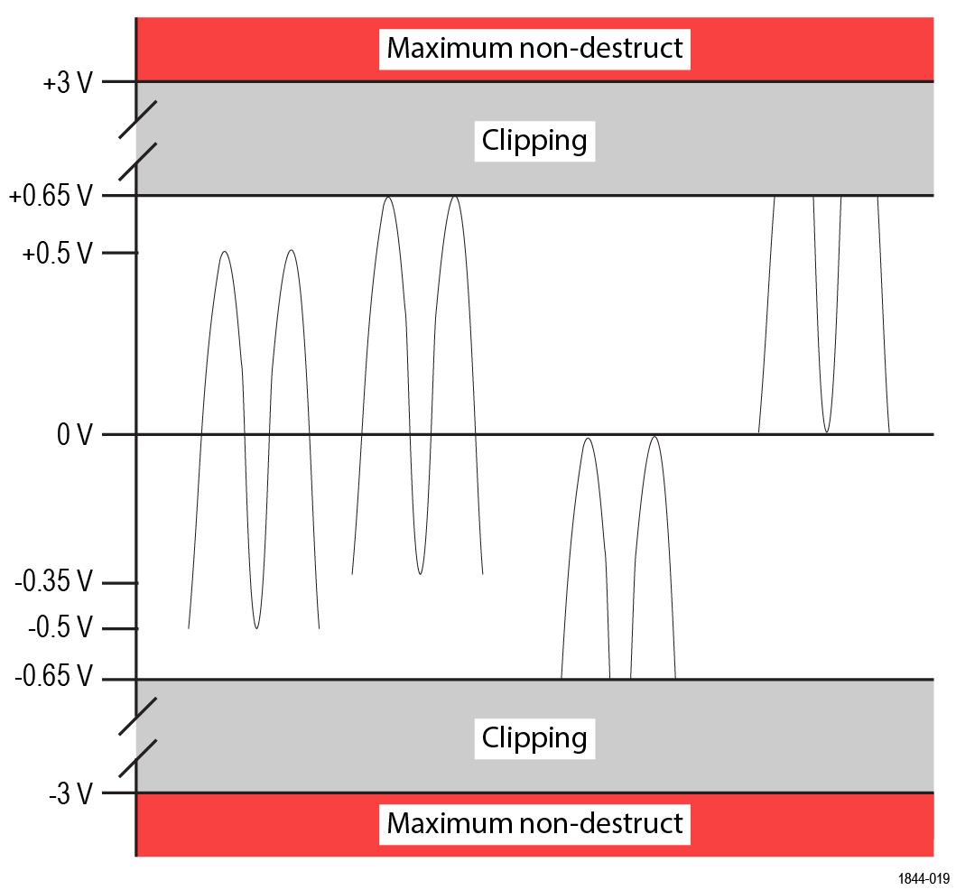
Noise floor (A RMS)

Shunt selection | 20 MHz | 250 MHz | 1 GHz |
|---|---|---|---|
50 Ω TICP as shunt | 420 nA | 1.5 μA | 3.0 μA |
5 Ω shunt | 4.2 μA | 14.9 μA | 29.7 μA |
1 Ω shunt | 21 μA | 74.3 μA | 149 μA |
500 mΩ shunt | 42 μA | 149 μA | 297 μA |
50 mΩ shunt | 420 μA | 1.5 mA | 3.0 mA |
5 mΩ shunt | 4.2 mA | 14.9 mA | 29.7 mA |
500 μΩ shunt | 42 mA | 149 mA | 297 mA |
50 μΩ shunt | 420 mA | 1.5 A | 3.0 A |
15 μΩ shunt | 1.4 A | 5.0 A | 9.9 A |
Shunt selection | 20 MHz | 120 MHz | 250 MHz |
|---|---|---|---|
5 Ω (TICS5000) | 4.2 μA | 10 μA | 15 μA |
500 mΩ (TICS0500) | 42 μA | 100 μA | 150 μA |
50 mΩ (TICS0050) | 420 μA | 1.0 mA | 1.5 mA |
5 mΩ (TICS0005) | 4.2 mA | 10 mA | 15 mA |
The wideband shunt noise floor is dependent on TICP input range, bandwidth, and shunt value. Numbers above calculated with TICP in the ±20 mV range. | |||
Maximum measurable current
Maximum depends on shunt power rating.

Shunt selection | TICPMM1 | TICPSMA | TICPMM10 | TICPMM100 |
|---|---|---|---|---|
50 Ω TICP as shunt | 13 mA | - | - | |
5 Ω shunt | 130 mA | 1.3 A | 10 A | |
1 Ω shunt | 650 mA | 6.5 A | 50 A | |
500 mΩ shunt | 1.3 A | 13 A | 100 A | |
50 mΩ shunt | 13 A | 130 A | 1.0 kA | |
5 mΩ shunt | 130 A | 1.3 kA | 10 kA | |
500 μΩ shunt | 1.3 kA | 13 kA | 100 kA | |
50 μΩ shunt | 13 kA | 130 kA | 1000 kA | |
15 μΩ shunt | 43.3 kA | 433.3 kA | 3300 kA | |
Shunt selection | 10 μs | 1 ms | 100 ms | 1 s | 100 s |
|---|---|---|---|---|---|
5 Ω (TICS5000) | 0.2 A | 0.2 A | 0.2 A | 0.2 A | 0.2 A |
500 mΩ (TICS0500) | 2 A | 2 A | 2 A | 1.8 A | 1.5 A |
50 mΩ (TICS0050) | 20 A | 20 A | 7.6 A | 5.7 A | 4.6 A |
5 mΩ (TICS0005) | 195 A | 63 A | 23 A | 16 A | 12 A |
Derates based on current pulse width. Pulse Width durations are based on a Square Wave input. For Triangle Wave input (as in Double Pulse Test), the Maximum Pulse Width can be multiplied by 3.5. For example, for a double-pulse test that peaks at 20 | |||||
Probe Ranges
Numbers are published for TICPSMA and TICPMM1 tips. For 10X or 100X tips, multiply by 10 or 100 respectively.
Input range | Offset range | RMS noise spectral density (V | Noise floor at 20 MHz (V |
|---|---|---|---|
±0.5 V | ±0.15 V | 22.9 nV / √Hz | 102.5 µV |
±0.35 V | ±0.30 V | 17.4 nV / √Hz | 77.8 µV |
±0.25 V | ±0.40 V | 15.0 nV / √Hz | 67.2 µV |
±0.175 V | ±0.475 V | 9.5 nV / √Hz | 42.4 µV |
±0.125 V | ±0.5 V | 8.7 nV / √Hz | 38.9 µV |
±0.09 V | ±0.5 V | 6.3 nV / √Hz | 28.3 µV |
±0.065 V | ±0.5 V | 5.5 nV / √Hz | 24.7 µV |
±0.045 V | ±0.5 V | 4.7 nV / √Hz | 21.2 µV |
±0.03 V | ±0.5 V | 4.7 nV / √Hz | 21.2 µV |
±0.02 V | ±0.5 V | 4.7 nV / √Hz | 21.2 µV |
Wideband shunts CMRR
Sensor Tip Cable | DC | 1 MHz | 100 MHz | 250 MHz |
|---|---|---|---|---|
5 Ω (TICS5000) | 120 dB | 105 dB | 52 dB | 40 dB |
500 mΩ (TICS0500) | 120 dB | 105 dB | 67 dB | 55 dB |
50 mΩ (TICS0050) | 120 dB | 110 dB | 80 dB | 70 dB |
5 mΩ (TICS0005) | 120 dB | 110 dB | 90 dB | 82 dB |
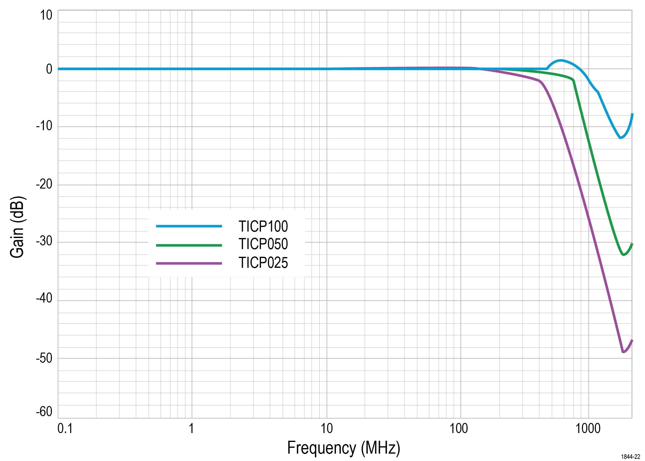
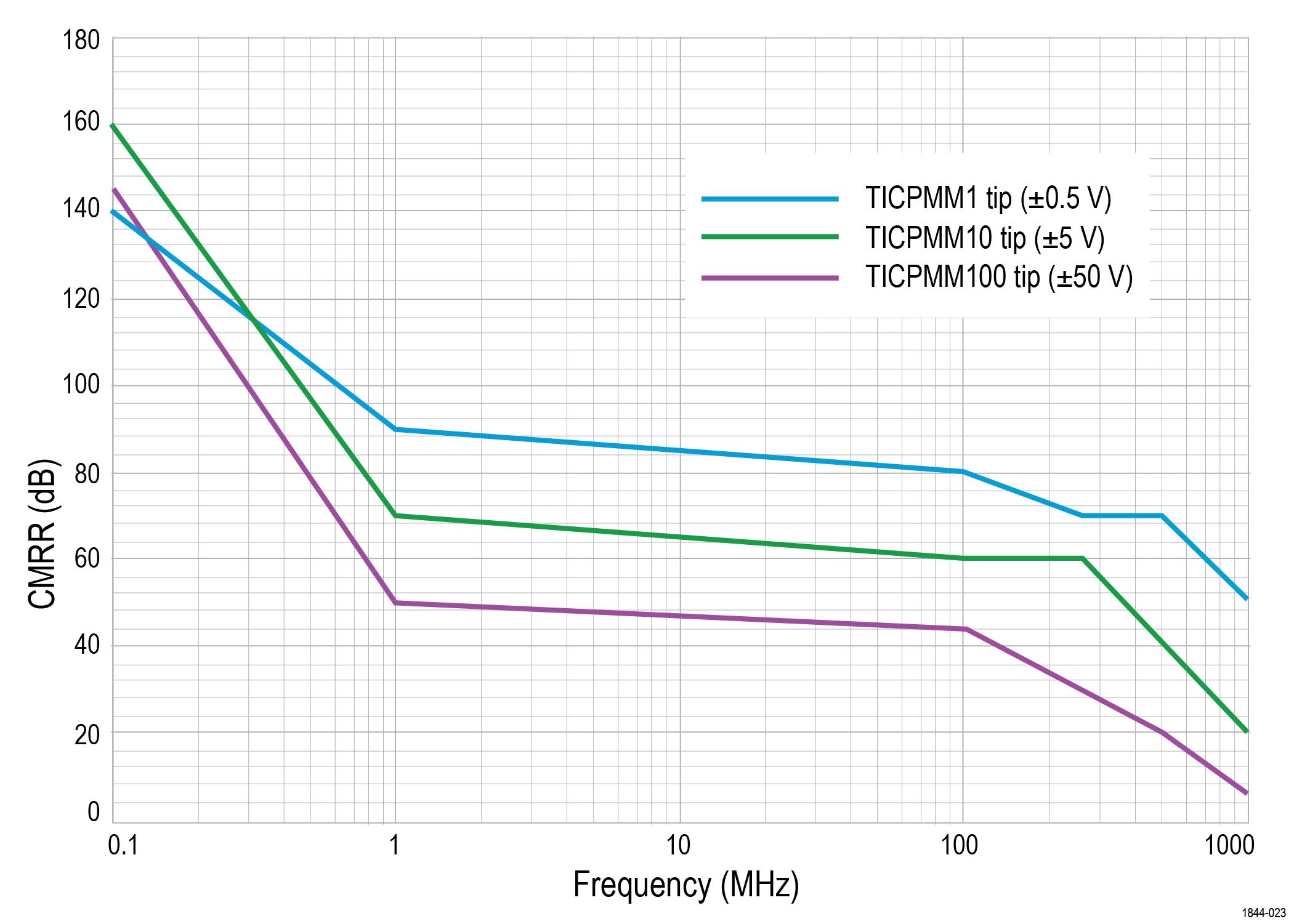
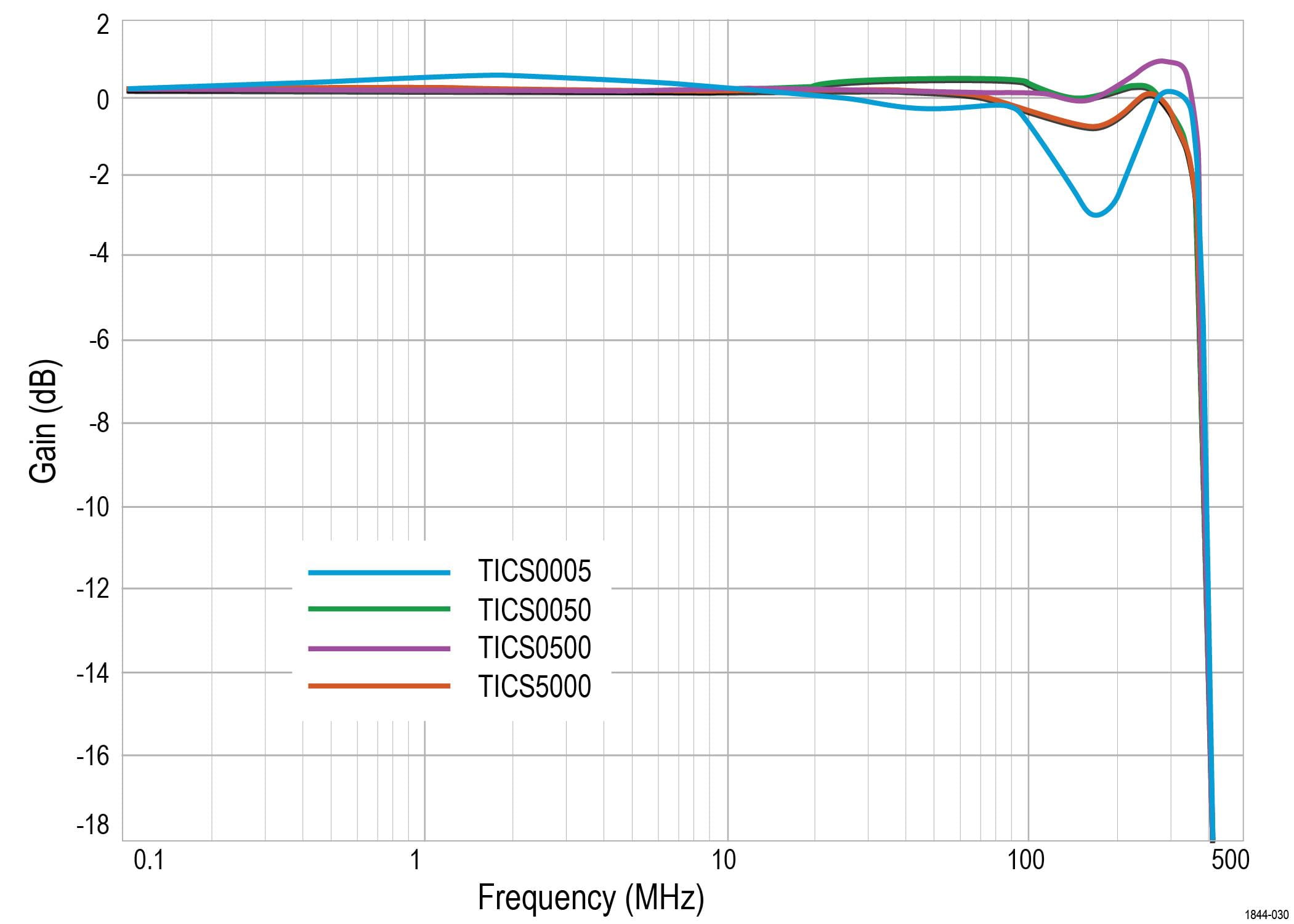
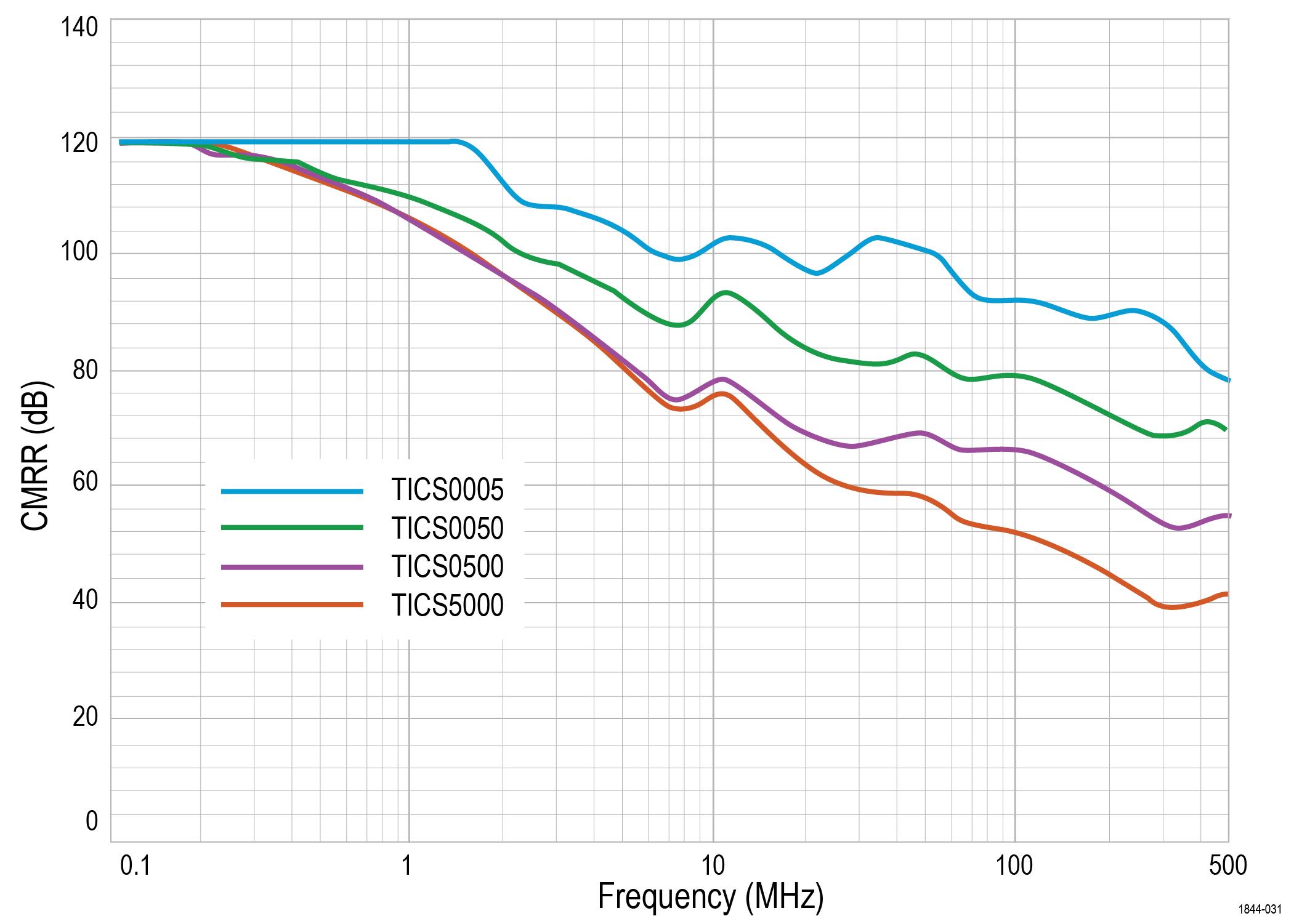
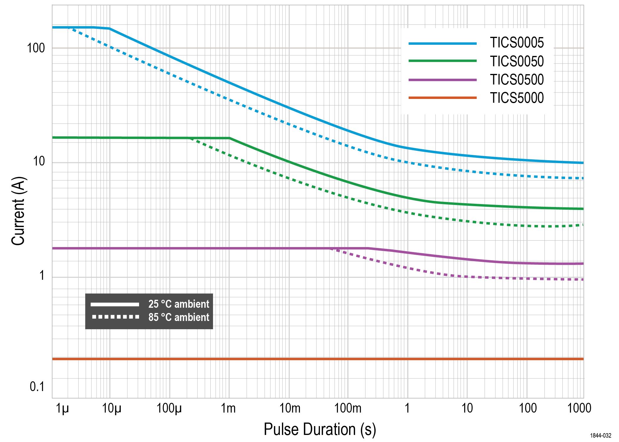
Pulse Width durations are based on a Square Wave input. For Triangle Wave input (as in Double Pulse Test), the Maximum Pulse Width can be multiplied by 3.5. For example, for a double-pulse test that peaks at 20 A, the 50 mΩ TICS can withstand a 3.5 ms ramp. A 20 A square wave impulse could only be held for 1 ms.
Wideband shunts pulse current derating calculations
Calculate max current for a square current pulse of width
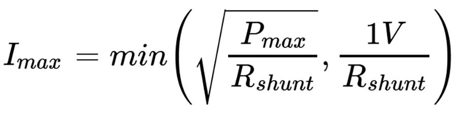
For an isolated pulse or ramp (effectively zero duty cycle):
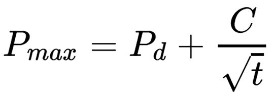
For repetitive operation with duty cycle
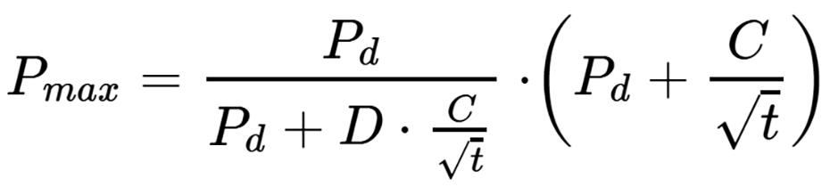
The coefficients
Shunt | 25°C | 85°C | ||
|---|---|---|---|---|
5 mΩ | 0.6 | 0.69 | 0.31 | 0.36 |
50 mΩ | 0.6 | 1.0 | 0.31 | 0.52 |
500 mΩ | 0.6 | 1.0 | 0.31 | 0.52 |
5 Ω | 0.6 | 1.0 | 0.31 | 0.52 |
Example
A pulse train double pulse test with 5 pulses starts at 0
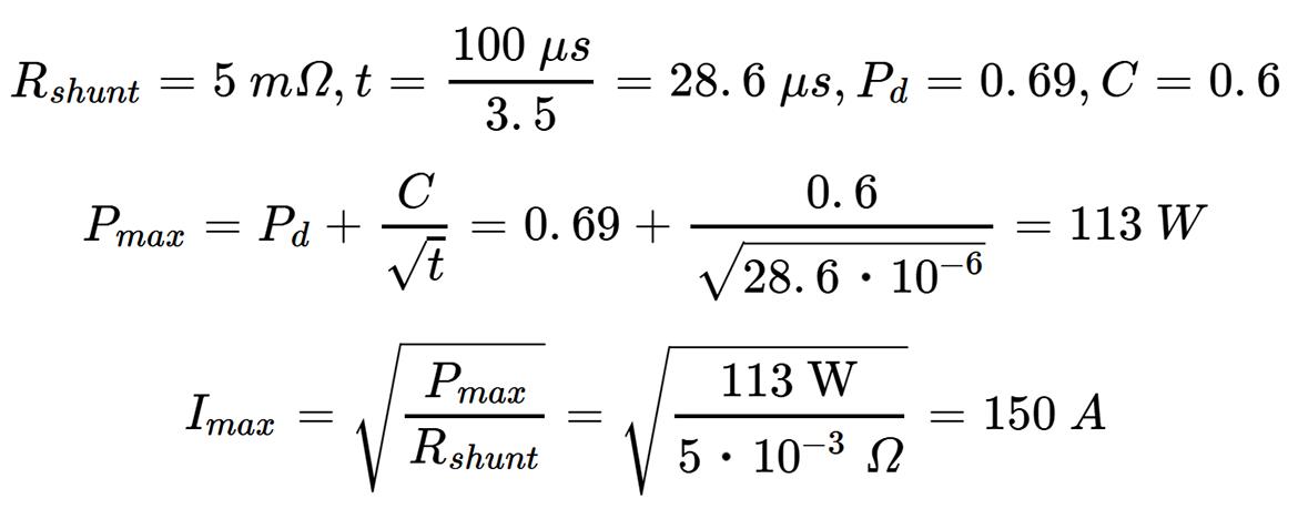
The calculation above shows the 5
Application Examples
Application examples for Wide Bandgap (WBG) and PMIC power integrity.
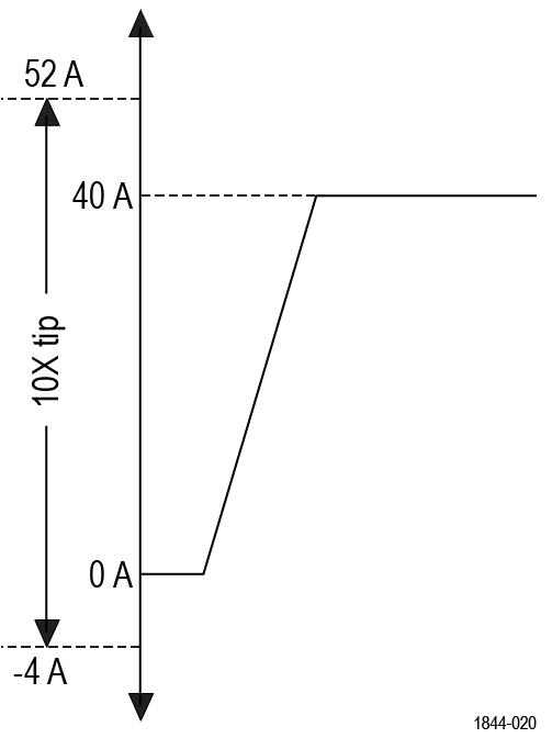
WBG example (800V, 40 A typical; 0.125 Ω shunt)
In a 800
The measurable current range goes from 52 A to -4 A. At these settings, the RMS noise floor at 250 MHz bandwidth is 2.2 mA RMS
PMIC power integrity (48 V, 3 mA typical; 1 Ω shunt)
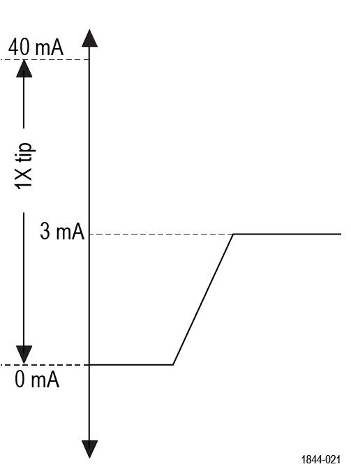
On a 48
Environmental requirements
Characteristic | Component | Operating | Non-operating |
Compensation box, probe head, and SMA tip adapter temperature | 0°C to +50°C | -20°C to +70°C | |
Standard tips temperature | TICPMM1, TICPMM10, TICPMM100, TICS0005, TICS0050, TICS0500, TICS5000, TICPTWCBL | -40°C to +85°C | -40°C to +85°C |
Extreme temperature tips (ET) temperature | TICPMM1ET, TICPMM10ET, TICPMM100ET | -40°C to +125°C | -40°C to +125°C; Storage temperature is -40°C to +85°C |
Humidity | All components | 5% to 85% relative humidity up to +40°C, 5% to 45% relative humidity up to +50°C, non-condensing | 5% to 85% relative humidity up to +40°C, 5% to 45% relative humidity up to +70°C, non-condensing |
Altitude | All components | Up to 3,000 meters | Up to 12,000 meters |
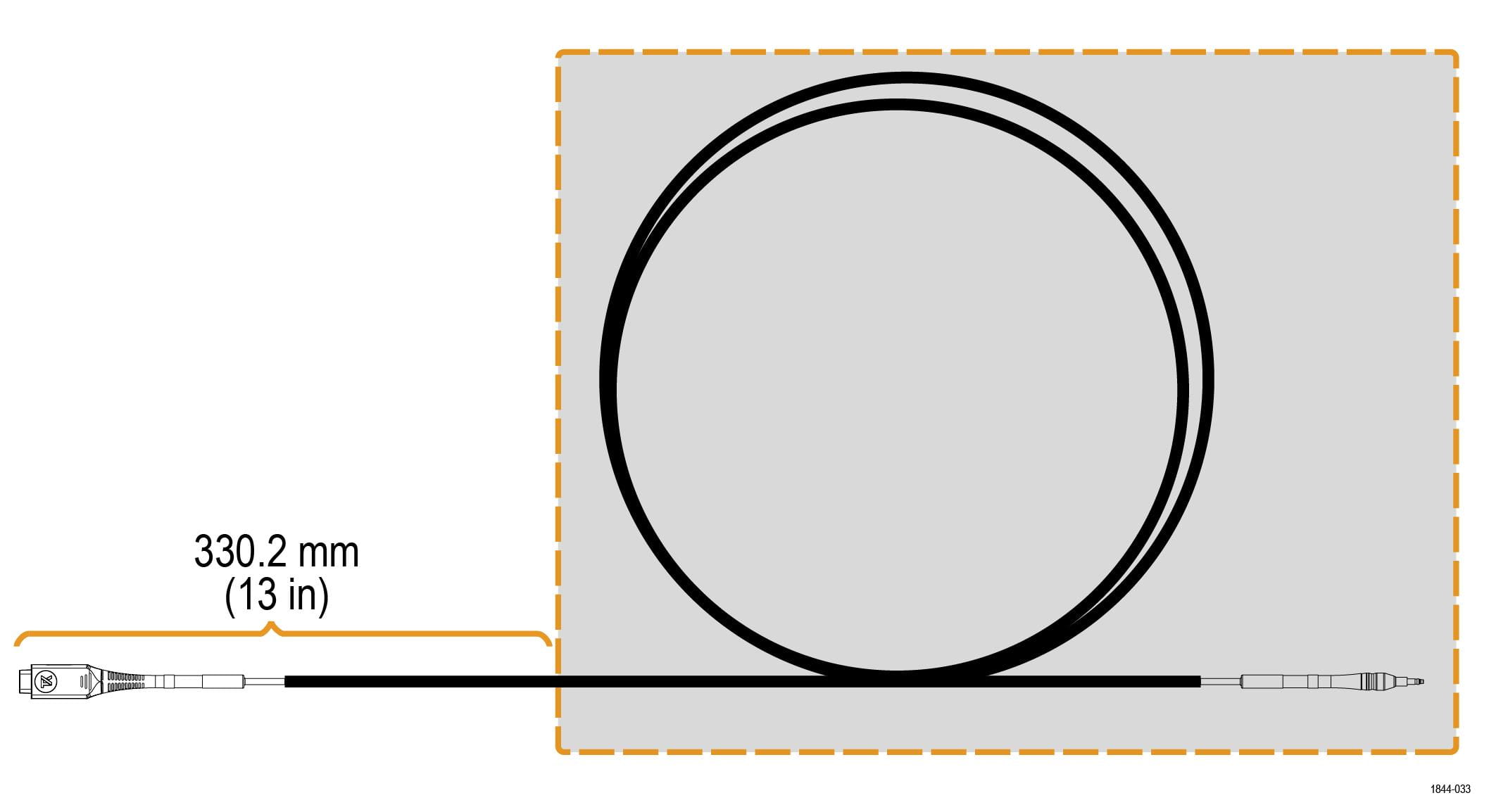
Tektronix extreme temperature (ET) tips enable accurate current measurements in environmental testing applications across an extended operating range of –40°C to +125°C.
In the illustration below, the shaded region within the dashed boundary indicates the recommended working zone for extreme temperature operation. To prevent environmental chamber access-port leakage from impacting the probe head, this working zone should begin at least 13 inches (330.2 mm) from the probe head.
Regulatory compliance
EMC
Conforms to European Union EMC Directive (CE-marked)
Safety
Conforms to European Union Low Voltage Directive (CE-marked)
Conforms to ANSI/UL61010-1 (CSA-marked)
Conforms to ANSI/UL61010-2-030 (CSA-marked)
Certified to CAN/CSA C22.2 No.61010-1 (CSA-marked)
Certified to CAN/CSA C22.2 No.61010-2-030 (CSA-marked)
RoHS
Conforms to European Union Restrictions on Hazardous Substances (CE-marked)
Ordering information
Select the appropriate instrument and options for your measurement needs.
Model overview
Model | Description |
|---|---|
250 MHz Tektronix Isolated Current Probe | |
500 MHz Tektronix Isolated Current Probe | |
1 GHz Tektronix Isolated Current Probe |
Standard accessories
The following table lists the accessories that are shipped with the probe.
Accessory | Description | Part number |
|---|---|---|
| 1X probe tip cable with MMCX connector | TICPMM1 |
| 10X probe tip cable with MMCX connector | TICPMM10 |
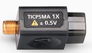
| SMA tip adapter | TICPSMA |
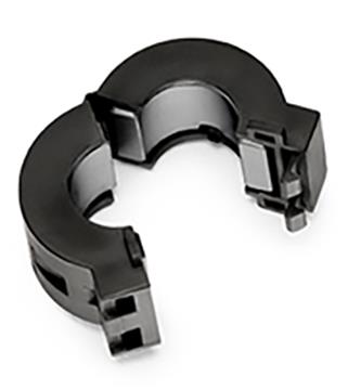
| Clamp-on ferrite common mode choke | 276-0905-XX |
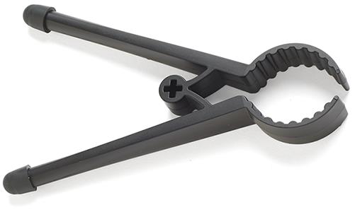
| Bipod is used to hold the probe. | 020-3210-XX |
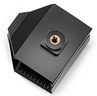
| Tripod adapter for ¼ in - 20 UNC thread accessories. | 103-0508-XX |
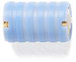
| Probe tip adapter. Adapts an MMCX IsoVu tip to standard 0.100" spaced, 0.025" square pins. | 131-9717-XX |
| Soft carrying case with foam insert. | 016-2147-XX |


Recommended accessories
The following table lists optional accessories.
Accessory | Description | Part number |
|---|---|---|
| 100X probe tip with MMCX connector | TICPMM100 |
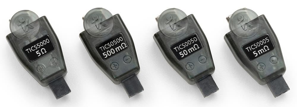
| TICP 5 mΩ low-power shunt | TICS0005 (Qty. 1) |
TICS0005PK (Qty. 10) | ||
TICP 50 mΩ low-power shunt | TICS0050 (Qty. 1) | |
TICS0050PK (Qty. 10) | ||
TICP 500 mΩ low-power shunt | TICS0500 (Qty. 1) | |
TICS0500PK (Qty. 10) | ||
TICP 5000 mΩ (5 Ω) low-power shunt | TICS5000 (Qty. 1) | |
TICS5000PK (Qty. 10) | ||
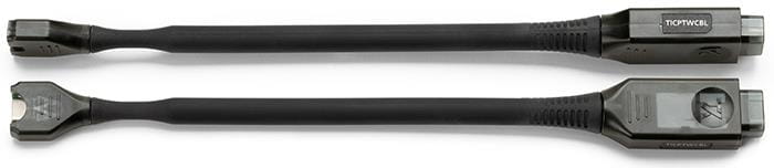
| TICP cable for shunts | TICPTWCBL (Qty. 1) |
TICPTWCBLPK (Qty 5) | ||
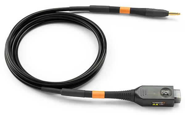
| 1X extreme temperature tip with MMCX connector | TICPMM1ET |
10X extreme temperature tip with MMCX connector | TICPMM10ET | |
100X extreme temperature tip with MMCX connector | TICPMM100ET | |
| Twisted pair solder-in accessory | 174-7492-XX |
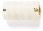
| Square pin to MMCX adapter, 0.062" spacing | 131-9677-XX |
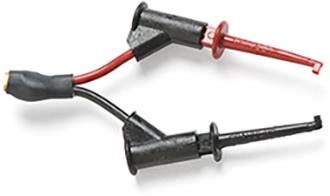
| MMCX to IC grabber lead | 196-3546-XX |
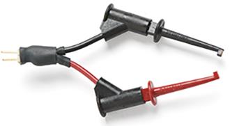
| Square pin to IC grabber lead | 196-3547-XX |
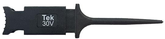
| MicroCKT grabbers | 206-0569-XX |


Supported oscilloscopes
The measurement systems can be used with the following Tektronix oscilloscopes.
4 Series MSO, 4 Series B MSO
5 Series MSO, 5 Series B MSO, 5 Series MSO LP
6 Series MSO, 6 Series B MSO
Service options
Standard warranty
1 year
Opt. T3
Three year total protection plan, includes repair or replacement coverage from wear and tear, accidental damage, ESD or EOS plus preventative maintenance. Including a 5 day turnaround time and priority access to customer support
Opt. T5
Five year total protection plan, includes repair or replacement coverage from wear and tear, accidental damage, ESD or EOS plus preventative maintenance. Including a 5 day turnaround time and priority access to customer support
Probes and accessories are not covered by the oscilloscope warranty and Service Offerings. Refer to the datasheet of each probe and accessory model for its unique warranty and calibration terms.