Background
With the expected dramatic rise in the number of internetconnected devices and associated high bandwidth requirements of 5G and Internet of Things (IoT), data center operators need to migrate to higher bandwidth networks than the 100 gigabit Ethernet (100GE) commonly in use today. Migrating to these next generation 400GE networks requires faster memory and higher speed serial bus communications.
In addition to upgrading Ethernet interfaces to 400GE, servers will need to utilise both higher-speed serial expansion bus interfaces and memory. The PCIe® (PCI Express) expansion bus is now moving to the recently standardised PCIe 5.0, otherwise known as PCIe Gen 5. At the same time DDR (Double Data Rate) memory is moving from DDR 4.0 to DDR≈5.0.
The PCIe Gen 5 specification was a fast track enhancement of the PCIe 4.0 standard developed by the PCI Special Interest Group (PCI-SIG®). PCI-SIG® is the standards body that defines all PCIe specifications. The PCIe 5.0 standard was recently completed with the finalisation of the PCIe 5.0 Card Electromechanical (CEM) specification, released in June 2021. This is a companion to the existing PCIe 5.0 Base (silicon) specification released in 2019.
Development of PCIe Standards
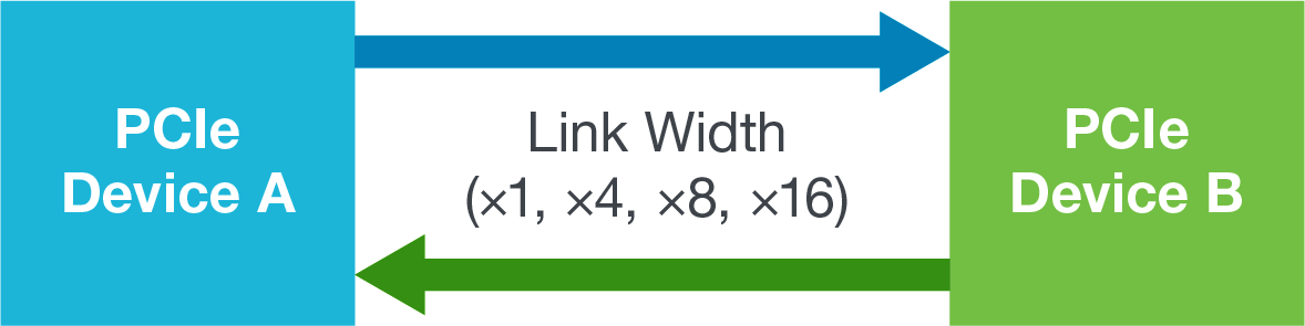
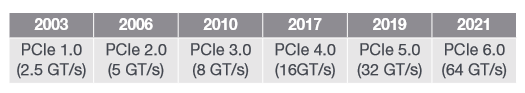
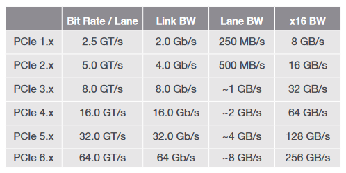
The original parallel PCI bus (Peripheral Component Interconnect bus) introduced in 1992 was designed to extend the capabilities of PCs by allowing the addition of graphics and networking cards as well as many other peripherals. PCIe is a high-speed serial bus designed to replace PCI as well as other now legacy interfaces such as PCI-X (PCI eXtended) and AGP (Accelerated Graphics Port). PCIe offers high throughput as well as a small form factor, with scalable link widths of ×1, ×2, ×4, ×8 and ×16 lanes. PCIe is based upon a point-to-point bus topology between a root complex (system/host) and an end-point (add-in card) that supports full duplex packet-based communications. The PCIe 1.0 standard was introduced in 2003 and offers 2.5 Giga Transfers/second (2.5 GT/s). PCIe currently delivers speeds from 2.5 GT/s up to 32 GT/s.
PCIe 5.0 doubles the PCIe 4.0 transfer rate from 16 GT/s to 32 GT/s, but it does not offer any significant additional features, as its goal was to deliver this extra speed in as short a time as possible.
All PCIe standards currently released use non-return to zero (NRZ) signalling. However, PCI-SIG is currently developing the PCIe Gen 6 specification which will again double the transfer rate to 64 GT/s and will move away from NRZ signalling.
Instead Gen 6 will use PAM-4 (4-level pulse amplitude modulation) signalling, along with a low-latency FEC (forward error correction) to improve data integrity.
All PCIe standards must be backwards compatible, which means that PCIe 5.0 (32 GT/s maximum data rate) must also support 2.5 GT/s, 5 GT/s, 8GT/s, 16 GT/s as well as 32 GT/s.
PCI-SIG® Overview
Founded in 1992, PCI-SIG (Peripheral Component Interconnect Special Interest Group) is a standards body with over 900 industry-wide member companies. Membership is open to any company interested in PCI technology. PCI-SIG is the developer of non-proprietary PCI technology standards and associated specifications including PCIe, which is now the de facto interconnect standard for servers. PCI-SIG defines PCI specifications to support the required i/o functionality, while maintaining backwards compatibility with earlier specifications. To enable industry wide adoption of PCI technology PCI-SIG offers support for both interoperability and compliance testing, including which tests need to be performed and passed to achieve compliance.
Tektronix is a key contributor to the PCI-SIG providing significant contributions to the PCIe 4.0 and 5.0 Physical Layer Test specifications and pathfinding experimentation for PCIe 6.0 Tx/ Rx measurement methodologies. Tektronix is also instrumental in compliance and interoperability testing during PCIe standards development and implementation.
PCIe Compliance Testing
PCI-SIG compliance workshops host interoperability testing to allow a member to test a product against other member’s products. The workshops also host compliance testing to allow for product testing against the PCI-SIG defined test suite. In both cases a product will either pass or fail. To achieve formal compliance a product must pass a minimum of 80 percent of the interoperability tests and pass all the normative (required) compliance tests. Tektronix has PCI-SIG approved test suites for all data rates (Tx, Rx, and PLL bandwidth).
Challenges Specific to PCIe 5.0
PCIe 4.0 at 16 GT/s was the previous speed enhancement to PCIe and proved to be more difficult to implement than earlier standards. With PCIe 5.0, computer PCIe channels and motherboards will be significantly challenged to handle the 32 GT/s data rate. Significant signal integrity challenges are anticipated with PCIe 5.0 devices beyond those encountered at the lower data rates.
PCIe 5.0 Transmitter Test Overview
When developing a PCIe Gen 5 transmitter device whether at the Base (silicon) or CEM (system and add-in card) level, it will require chip level validation (often performed by the PHY IP company) and pre-compliance testing prior to submitting the device for official compliance testing with the PCI-SIG. As such it is critical to have access to appropriate test equipment as well as the associated automation software.
PCIe compliance testing includes:
- Electrical Testing - Evaluates platform and add-in card Transmitter (Tx) and Receiver (Rx) characteristics
- Configuration Testing - Evaluates the configuration space in PCIe devices
- Link Protocol Testing - Evaluates a device’s link-level protocol behaviour
- Transaction Protocol Testing - Evaluates a device's transaction-level protocol behaviour
- Platform BIOS Testing - Evaluates the BIOS's ability to recognize and configure PCIe devices
With respect to electrical testing, this is split into two sets of measurements, one for the Base level and one for the CEM level. These tests are categorised as either normative or informative:
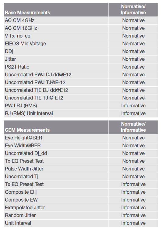
Both measurement categories require a high bandwidth real-time oscilloscope capable of capturing data waveforms. Post-processing is then employed to make the appropriate voltage and timing measurements required in the Base and CEM specifications. Uncorrelated jitter explores the intrinsic jitter to the system once the impact of package and channel Inter-Symbol Interference (ISI) is removed. As well as jitter, the oscilloscope is needed to make eye height and width measurements. Numerous “compliance patterns” are defined in the Base specification. A waveform record containing multiple occurrences of the full compliance pattern is recommended to construct a representative eye diagram.
In Base Tx testing of devices, measurements are specified directly at the pins of the transmitter. If direct access is not possible then the test points should be as close as possible to the device pins. Any breakout channel loss can be de-embedded if the user has a good knowledge of the S-Parameters through a physical replica channel or simulation. An alternate methodology to de-embedding was described starting in the 4.0 specification where a CTLE (Continuous Time Linear Equalization) is applied during waveform postprocessing for the uncorrelated jitter measurements, effectively removing ISI back to the pins.
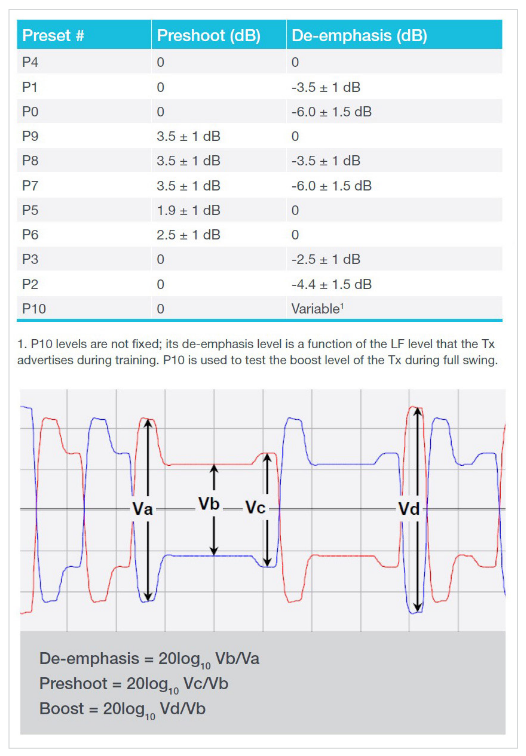
Any PCIe 5.0 product that is submitted for PCI-SIG certification must successfully pass compliance testing using defined presets of Tx equalizer settings at speeds from 2.5 GT/s up to 32 GT/s. These presets are used to equalize inter-symbol interference caused by frequency dependent attenuation differences within the bit stream, providing improved signal integrity. Each preset is a specific combination of preshoot (pre-cursor) and de-emphasis (post-cursor).
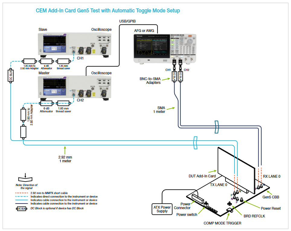
Numerous implementation specific methods exist to sweep the DUTs transmitter through the data rates and Tx EQ Presets. However, the Base specification defines a common approach where a 100 MHz clock burst is delivered to Lane 0 of the receiver. This can be automated with the use of an arbitrary function generator (AFG).
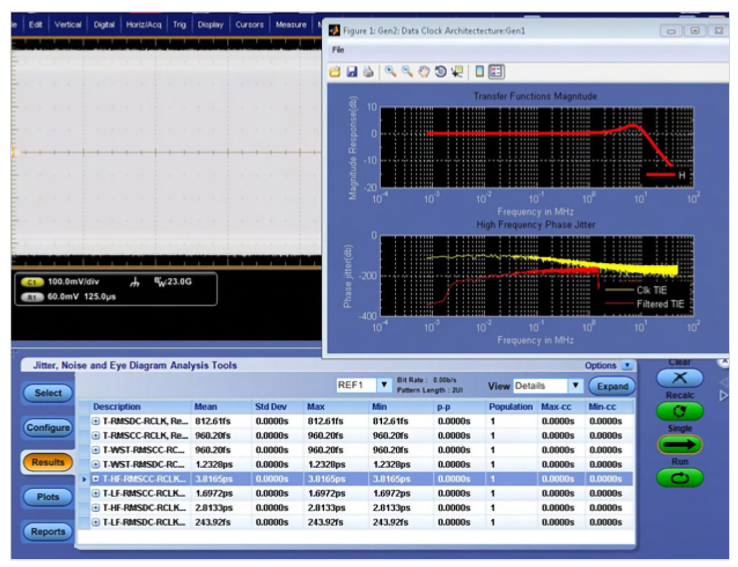
New validation challenges are present for Reference Clocks (Refclks) targeted for PCIe links with a maximum data rate of 32 GT/s. The Base specifications has been scaling the jitter limits with data rate, but Gen5 disproportionality dropped the limit to 150 fs. This high frequency jitter measurement requires proper application of the common clock transfer function with worst case transport delays considered. This latest specification revision also pushed the measurement from a Base specification (chip-level) to also being a CEM specification requirement (form factor level) necessary for compliance.
Oscilloscope Bandwidth and Sample Rate Requirements
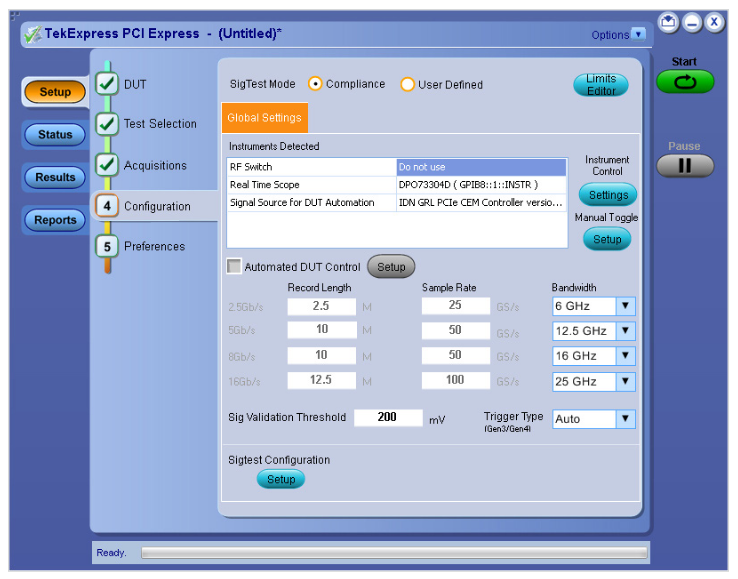
For Base Tx testing, each PCIe 5.0 lane operates at 16 GHz (since two bits can be transmitted in a single period), putting the 3rd harmonic at 48 GHz. As there is not much significant signal information above the 3rd harmonic, a 50 GHz bandwidth real-time oscilloscope is needed for PCIe 5.0 Base Tx testing. For CEM Tx testing the measurements are taken near the end of a worst-case channel which reduced the high frequency content allowing a bandwidth requirement of 33 GHz. For adequate waveform post-processing (SigTest) it was determined a minimum of 4 points per unit interval was required . This leads to minimum sample rate of 128 GS/s with an CEM allowance for up to 2x sinx/x interpolation.
Compliance Test Automation
Manually performing the analysis for compliance testing is both time consuming and error prone. To save time, it is highly desirable to use automation software which reduces effort and accelerates compliance testing. For electrical validation, the PCI-SIG offers the SigTest offline analysis software which uses acquisitions from an oscilloscope to perform the analysis. Automation software can also control the device under test (DUT) using an arbitrary Function Generator as a pattern source to automatically cycle the DUT through various speeds, de-emphasis, and presets that are necessary for the compliance test.
A complete compliance test run requires multiple waveforms to be acquired at different DUT settings per lane. This waveform set will increase by the number of lanes (up to 16) that need to be analysed. The ability for the software to manage and store the required data for analysis and future reference is an important criterion for any compliance solution. Automation software can also adjust oscilloscope horizontal and vertical settings as well as the acquisition depth.
As well as configuration and analysis, automation software can be used to manage multiple acquired waveforms. If PCISIG’s SigTest is used to analyse the acquired waveforms, the results of the analysis will be consistent with the SigTest post-capture analysis software used at PCI-SIG workshops for compliance testing.
Automation software can select data rates, voltage swing, presets, and the tests to be executed. It can also provide the option to embed package s-parameter models and de-embed the effects of cables, test fixtures, or other elements needed to reach target test points defined in the specifications.
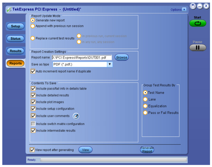
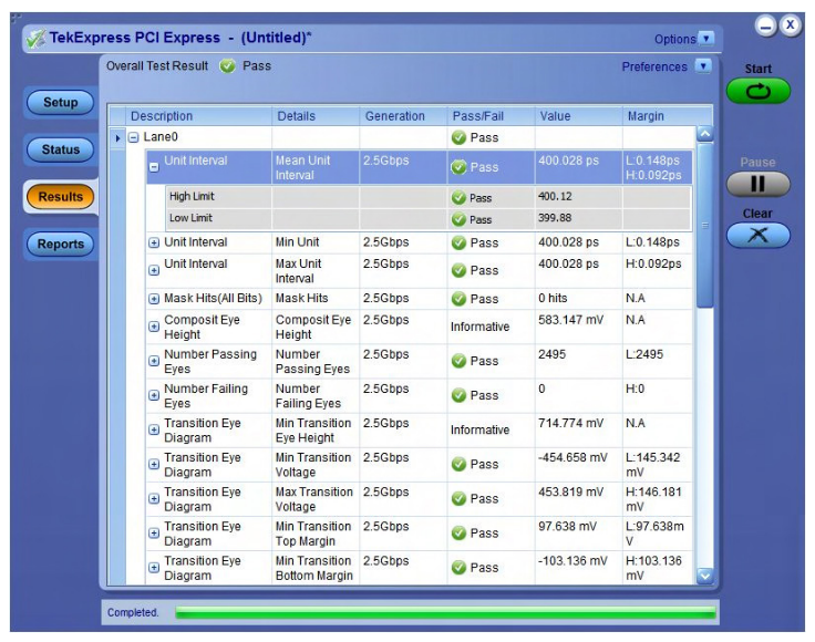
Often the analysis results from the software can be compiled into a PDF or HTML formatted report, that may include pass/fail summary, eye diagrams, setup configuration and user comments.
Summary
With Base level (silicon) transmitter testing, voltage and jitter measurements are specified directly at the pins of the transmitter. Since direct access to the pins is sometimes impossible, measurements should be taken as close as possible to this reference point. Using a reference channel with known s-parameters to characterize and de-embed is recommended for these voltage measurements, and jitter measurements now utilize the CTLE curves to remove the impact of the break-out channel for uncorrelated jitter characterization.
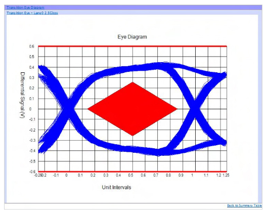
With CEM level (system and add-in card) transmitter testing, measurements are specified at the receiver. Test fixtures enable signal access while also constructing part of the channel and embedding creates the remaining loss. The eye diagram is viewed after waveforms are post-processed to include the benefit of clock recovery and receiver equalization.
In both cases it is vital to use a real-time oscilloscope with adequate bandwidth and sample rate. Automation software can be used to make the debug, validation and compliance as quick and simple as possible.
Tektronix PCIe Solutions
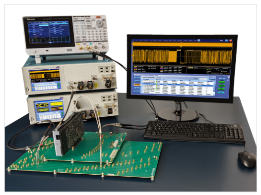
Using the Tektronix DPO70000SX Series Oscilloscopes and AFG31252 Arbitrary Function Generators, the PCI Express Gen1/2/3/4/5 solution offers automated validation and compliance of Transmitters at the BASE (silicon) and CEM (system and add-in card) levels.
The TekExpress PCIe 5.0 Tx automation software capabilities:
- Autonomously steps the DUT through different speeds, patterns, and Tx EQ presets.
- Verifies the correct signal at the transmitter before taking measurements.
- Performs channel and package embedding and deembedding.
- Supports SigTest and SigTest Phoenix software versions and template files.
- Performs 100 MHz reference clock jitter and signal integrity measurements with Silicon Labs. "PCIe Clock Jitter Tool" and Tektronix DPOJET software.
Historically, when a new generation of PCIe devices enters compliance testing, a significant percentage of them fail their first interoperability workshop for PHY and link training compliance. It is vital to have a comprehensive Oscilloscope, AFG, BERT (for Rx testing) and automation software solution in place prior to any workshop testing. Tektronix PCIe test and debug Tx, Refclk and Rx solutions can guide you through compliance testing and debug prior to an interoperability workshop. This ensures that your design meets the PCI-SIG® PCIe standards requirements with a high degree of confidence.