Introduction
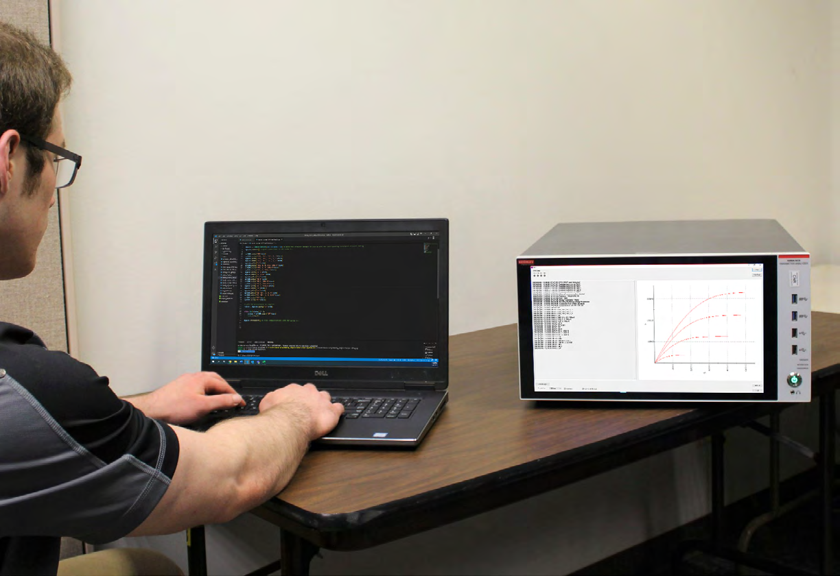
The Keithley External Control Interface (KXCI) allows remote control of the instrument modules contained within the Keithley 4200A-SCS Parameter Analyzer by sending external commands from a PC. Each KXCI command has a specific function for the different instruments. There are different command sets for KXCI, including the following: SMU commands, CVU commands, PMU/PGU commands, and commands to call user libraries. These commands are sent to the KXCI User Interface on the 4200A-SCS, which is used to graph desired results, log received commands and display error messages.
The controlling PC can be connected to the 4200A-SCS via GPIB or ethernet to remotely send KXCI commands via a coding environment. Visual Studio Code, when used with Python 3 and NI VISA, provides an easy use coding environment to read, write and query KXCI commands for a desired test.
This application note describes how to set up a PC and the 4200A-SCS for remote control using Visual Studio Code and Python, as well as various examples of Python scripts written with KXCI commands to perform tests.
How to Set Up a PC to Send Remote Commands Using Python
For instructions on setting up Python and Visual Studio Code for instrument control, please refer to the guide Getting Started with Instrument Control Using Python 3 – VS Code Revision, which can be downloaded here in the Keithley GitHub folder. This document describes the installation of Python, Visual Studio Code, and NI-VISA tools for remote commands. The document also includes a link to a file written by Keithley that provides wrapper functions for the PyVISA library. These wrapper functions are used within each of the scripts to automate commands, which is included in a library called "instrcomms.py".
Install these tools and set them up according to the instructions. This application note will explain how to write program examples that are streamlined to the 4200A-SCS.
How to Set Up the 4200A-SCS for Remote KXCI Commands Using Python on Ethernet
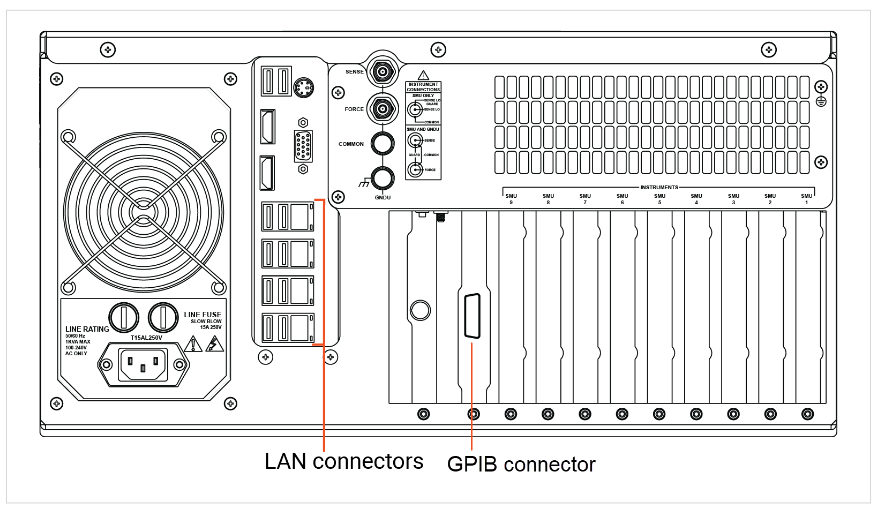
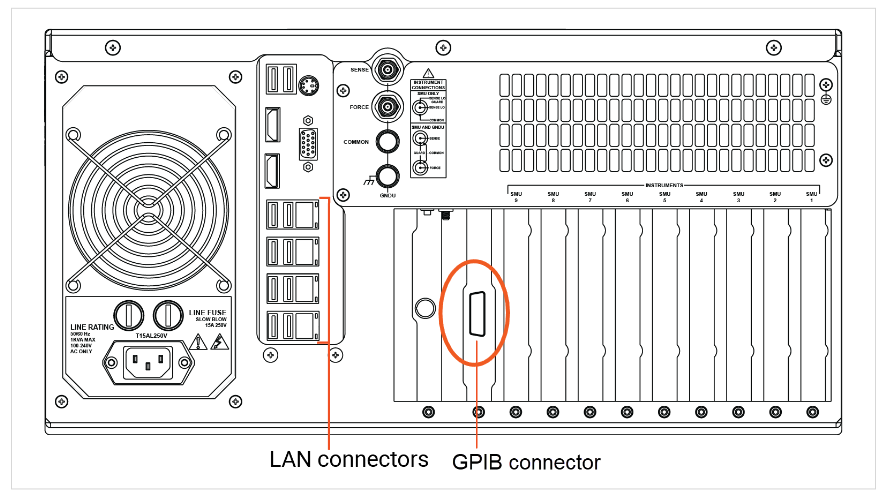
Figure 1 shows the back panel of the 4200A-SCS and the LAN connectors.
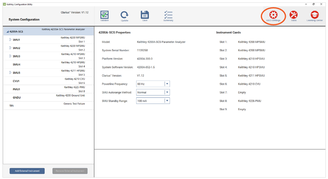
To begin, connect an ethernet cable from the PC to the 4200A-SCS. On the 4200A-SCS, open the Keithley Configuration Utility (KCon) application, which allows for configuration of the type of communication that is being used. Access the KXCI Settings in the upper right as circled in Figure 2.
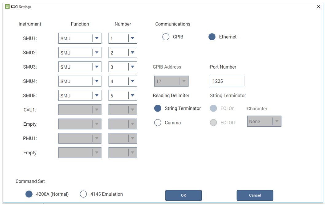
Within the settings screen, select Ethernet under the Communications section. Take note of the port number, as this will be used in the Python script to communicate with the 4200A-SCS. Select the String Terminator as the Reading Delimiter, and then select OK at the bottom of the window. Next, save and exit within KCon. Each KXCI command that is sent via ethernet must be terminated with the NULL terminator, otherwise known as the string terminator. Figure 3 shows the KXCI settings screen configured for ethernet connection.
Next, search for NI MAX in the PC search bar. NI MAX was installed from the Getting Started with Instrument Control Using Python 3 – VS Code Revision document that was previously described in the PC setup section. Once that is open, expand the arrow next to My System. Expand the arrow under Devices and Interfaces, then right click on Network Devices. Click on Create New VISA TCP/IP Resource… Figure 4 shows the NI MAX screen.
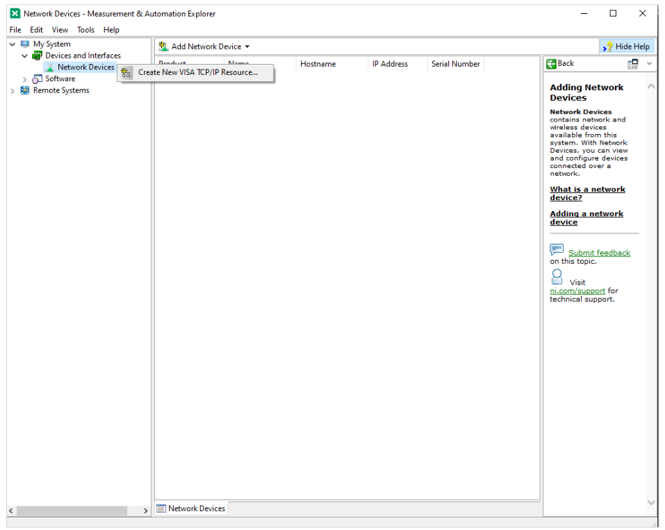
Within this submenu, select Manual Entry of Raw Socket. Enter the IP address of the 4200A-SCS unit that is being used, as well as the port number for ethernet that was found in the KCon KXCI settings.
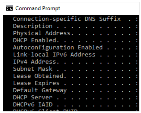
To find the IP address of the 4200A-SCS, open the Command Prompt by searching for "cmd” in the Window's search bar. Once the command prompt is open, type ipconfig /all and press enter. A list of IP properties will appear, but the one that is of interest is the "IPv4 Address." An example of this screen is shown in Figure 5.
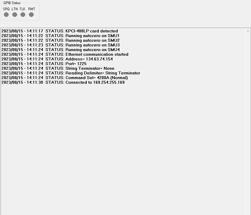
Once this information is entered, open up KXCI. With KXCI running, select "Validate" in NI MAX. If successful communication was established, a window will appear saying "Successfully opened a VISA session" as shown in Figure 6, and KXCI will show a connection was established as shown in Figure 7.
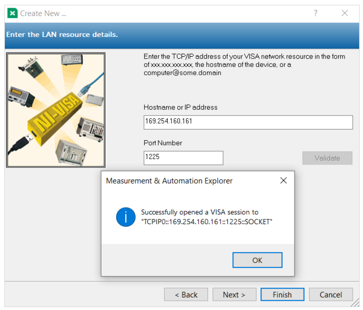
Next, select "Finish" in NI MAX. The 4200A-SCS VISA Resource Name will appear under the Network Devices section. The resource name string will be in the format “TCPIP0::XXX.XXX.XX.XXX::1225::SOCKET,” where the X’s are replaced with the respective 4200A-SCS IP address. Make note of this resource name, as it will be used to communicate with the 4200A-SCS within the Python scripts for tests. The 4200A-SCS is now ready for communication from the PC using KXCI via ethernet.
How to Set Up the 4200A-SCS for Remote KXCI Commands Using Python on GPIB
Figure 8 shows the back panel of the 4200A-SCS, and the circled section shows the GPIB connection port.
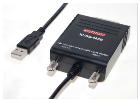
To connect a PC to the 4200A-SCS using a GPIB cable, a GPIB to USB adapter is needed if the PC does not have a GPIB port. The KUSB-488B is a Keithley adapter that can be used for this purpose (Figure 9).
To support the KUSB-488B on the PC, drivers must be installed. The drivers can be found on the Tektronix website here. Click on Download File, and then locate the file in the PC’s downloads folder. Extract the zip file to the location of the user’s choosing. Next, right click on the file called "KI-488.exe” and run as administrator. Follow the on-screen instructions for the installation of the drivers. This application note uses a version of the driver that is NI Command Compatible. Note that installation of this device may conflict with previously installed USB to GPIB converters such as a National Instruments model. The installer may overwrite these conflicting files or request that the other drivers be uninstalled first.
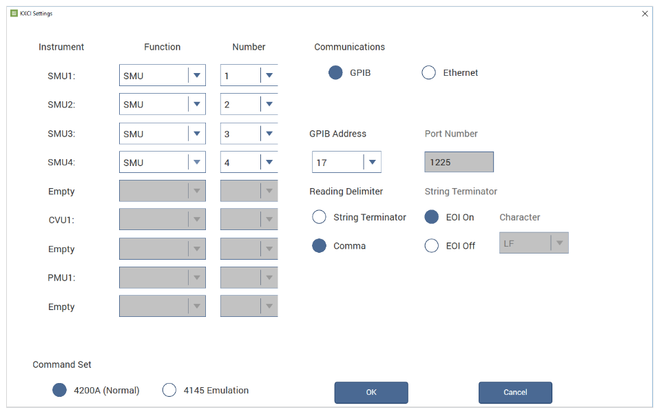
Connect the PC to the 4200A-SCS using the KUSB-488B adapter. Next, open the KCon application and locate the KXCI settings (see Figure 2). Within the KXCI settings, select GPIB from the Communications section. Make note of the GPIB address, as it will be needed for communication to the 4200A-SCS. Select comma as the reading delimiter and select EOI on. Unlike ethernet commands, GPIB commands do not require the NULL terminator to be sent. Select OK, then save and exit the KCon configuration after changing the settings. The settings will look like the ones shown in Figure 10.
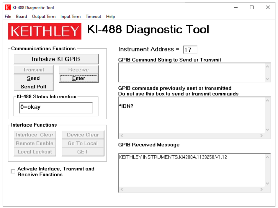
Once the drivers are installed and the KUSB-488B is connected to the PC, it is possible to verify the connection from the PC to the 4200A-SCS. The KUSB-488B driver includes the KI-488 Diagnostic Tool application, which can be found by searching in the PC search bar. Locate this tool on the PC and open it. Once opened, ensure that the Instrument Address at the top of the tool matches the address that was shown in KCon. Once entered, click Initialize KI GPIB in the Communications Functions section shown in Figure 11.
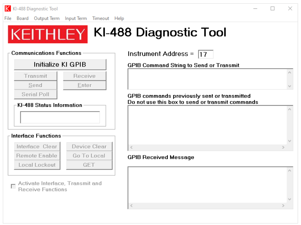
Within the KI-488 Diagnostic Tool, it can be verified that the 4200A-SCS (with the KXCI application opened) is properly connected to the PC via GPIB. To test the status of the 4200A-SCS, enter *IDN? to the GPIB Command String to Send or Transmit box. Click Send to send the command to the 4200A-SCS. Once sent, the Enter button may be pressed to see the received message in the GPIB Received Message box. An example of this is shown in Figure 12. Once successfully connected, the KI-488 Diagnostic Tool may be closed.
Next, verify if the 4200A-SCS can be found in NI-VISA. Search for NI-VISA Interactive Control within the PC’s search bar. NI-VISA Interactive Control was installed from the Getting Started with Instrument Control Using Python 3 – VS Code Revision, which was previously described in the PC setup section. There will be a resource string under the devices that says GPIB Instrument Resources. This contains all available GPIB resources by their resource strings such as GPIB0::XX::INSTR, where XX is the address set in KCon as shown in Figure 13.
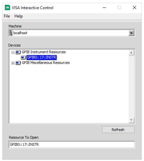
Take note of the resource string that is shown, as it will be needed for the Python scripts communication to the 4200A-SCS. NI-VISA Interactive Control may be closed. Open the KXCI Interface on the 4200A-SCS, and it is now ready for communication from the PC using KXCI via GPIB.
Example 1: MOSFET Drain Family of Curves Using Ethernet
The first example generates the MOSFET family of curves in the KXCI interface on the 4200A-SCS. The ID-VD curves will be displayed on the KXCI Interface graph when executed.
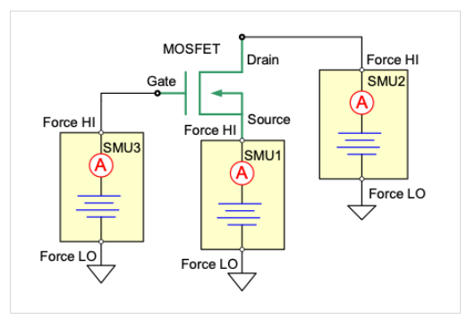
This example uses three source measure units (SMUs) at each terminal of the MOSFET as configured in Figure 14. SMU1 is connected to the Source terminal, SMU2 is connected to the Drain terminal, and SMU3 is connected to the Gate terminal.
Ensure that the proper steps for configuring ethernet KXCI connections were set in KCon as described in a previous section of this application note. Before any scripting, ensure that there is a device in the test fixture connected to the 4200A-SCS.
To begin open Visual Studio Code, right click within Visual Studio Code in the Explorer pane and select New File. Name the file family_of_curves_ethernet.py or something similar as long as it is ending in .py. The code for this example is shown below. The code may be copy and pasted. Ensure that the instrcomms.py file is in the project folder, such that it may properly be imported into the test that is being created. Modifications may need to be made to the SMU settings depending on the particular MOSFET that will be tested.
Example Code #1: MOSFET Drain Family of Curves Using Ethernet
import time from instrcomms import Communications
term = '\0' # terminating character for ethernet commands
INST_RESOURCE_STR = "TCPIP0::192.0.2.0::1225::SOCKET" # instrument resource string, obtained from NI MAX
my4200 = Communications(INST_RESOURCE_STR) # opens the resource manager in PyVISA with the corresponding instrument resource string
my4200.connect() # opens connections to the 4200A-SCS
my4200.write("DE"+term)
my4200.write("CH1, 'VS', 'IS', 1, 3"+term)
my4200.write("CH2, 'VD', 'ID', 1, 1"+term)
my4200.write("CH3, 'VG', 'IG', 1, 2"+term)
my4200.write("SS"+term)
my4200.write("VR1, 0, 5, 0.1, 100e-3"+term)
my4200.write("VP2, 1, 4, 100e-3"+term)
my4200.write("VC1, 0, 100e-3"+term)
my4200.write("HT 0"+term)
my4200.write("DT 0.001"+term)
my4200.write("IT2"+term)
my4200.write("RS 5"+term)
my4200.write("RG 1, 100e-9"+term)
my4200.write("RG 2, 100e-9"+term)
my4200.write("RG 3, 100e-9"+term)
my4200.write("SM"+term)
my4200.write("DM1"+term)
my4200.write("XN 'VD', 1, 0, 5"+term)
my4200.write("YA 'ID', 1, 0, 0.04"+term)
my4200.write("MD"+term)
my4200.write("ME1"+term)
# wait for measurement to complete
status = my4200.query("SP"+term)
while int(status) != 1:
status = my4200.query("SP"+term)
time.sleep(1)
my4200.disconnect() # close communications with the 4200A-SCS
Ensure that the INST_RESOURCE_STR matches what was displayed in NI-MAX in the setup section for ethernet. Descriptions of each of the KXCI commands are listed in Table 1. The action of the non-KXCI commands in the Python script are commented such that their purpose is clear.
| KXCI Command | Description |
| BC | Clears all readings from the buffer |
| DE | Selects the channel definition page |
| CH1, 'VS', 'IS', 1, 3 | Sets up SMU1 (CH1) to V source, constant function |
| CH2, 'VD', 'ID', 1, 1 | Sets up SMU2 (CH2) to V source, sweep function |
| CH3, 'VG', 'IG', 1, 2 | Sets up SMU3 (CH3) to V source, step function |
| SS | Selects the source setup page |
| VR1, 0, 5, 0.1, 100e-3 | Configures SMU1 to start sweep at 0V, stop at 5V, and step 0.1V with a compliance of 100mA |
| VP2, 1, 4, 100e-3 | Configures SMU2 to step from 1V to 4V with a compliance of 100mA |
| VC1, 0, 100e-3 | Configures SMU1 to output constant voltage of 0V with compliance of 100mA |
| HT 0 | Sets a hold time of 0s |
| DT 0.001 | Sets the time to wait between when the output voltage is set and when measurement is made in the sweep to 1ms |
| IT2 | Sets the integration time to 1.0 PLC |
| RS 5 | Sets the measurement resolution for all channels to 5 digits |
| RG 1, 100e-9 | Sets lowest range of SMU1 to 100nA |
| RG 2, 100e-9 | Sets lowest range of SMU2 to 100nA |
| RG 3, 100e-9 | Sets lowest range of SMU3 to 100nA |
| SM | Selects the measurement setup page |
| DM1 | Prepares 4200A-SCS to receive graphics commands |
| XN 'VD', 1, 0, 5 | Configures X-axis of graph to plot VD |
| YA 'ID', 1, 0, 0.04 | Configures Y-axis of graph to plot ID |
| MD | Selects the measurement control page |
| ME1 | Runs a single trigger test and stores readings in cleared buffer 1 |
| SP | Acquires the GPIB serial poll byte when ethernet communications are enabled. This returns 0 when the measurement is complete |
Table 1. KXCI command list for family of curves.
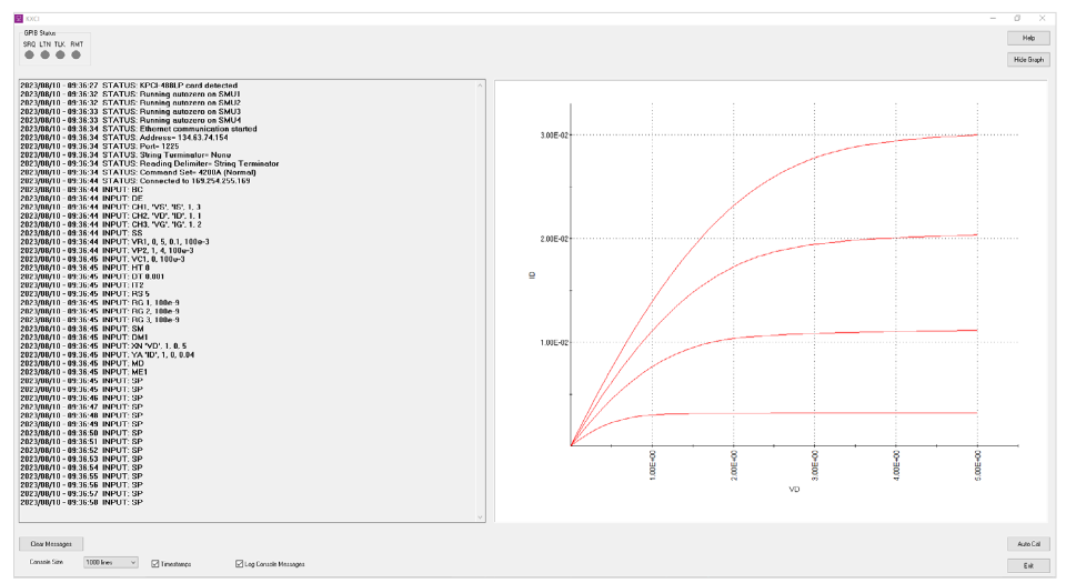
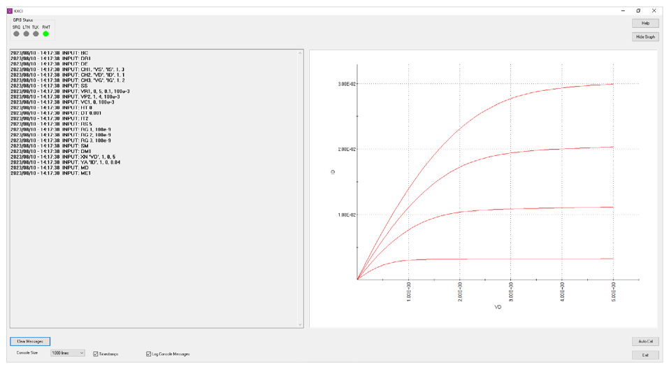
To execute this code, select Run Python File that is in the top right of the Visual Studio Code window. Figure 15 shows the results on the KXCI interface of the 4200-SCS after the test is executed. Notice the code is shown on the left-hand side of the display, and the drain family of curves is plotted on the right-hand side.
Example 2: MOSFET Drain Family of Curves Using GPIB
This next example also generates the MOSFET family of curves in the KXCI interface, so it is the same circuit setup as the first example (see Figure 14). However, this example is set up using GPIB rather than ethernet. Ensure that the proper steps for configuring KXCI with GPIB connection within KCon were taken as described in the previous section on setting up GPIB. To begin, open Visual Studio Code and right click in the Visual Studio Code‘s Explorer pane and select New File. Name the file family_of_curves_gpib.py or something similar and then Enter. The code can be copied and pasted for this example as shown below. Ensure that the instrcomms.py file is in the project folder, such that it may properly be imported into the test that is being created.
Example Code #2: MOSFET Drain Family of Curves Using GPIB from instrcomms import Communications
INST_RESOURCE_STR = "GPIB0::17::INSTR" # instrument resource string, obtained from NI-VISA Interactive
my4200 = Communications(INST_RESOURCE_STR) # opens the resource manager in PyVISA with the corresponding instrument resource string
my4200.connect() # opens connections to the 4200A-SCS
my4200.write("DE")
my4200.write("CH1, 'VS', 'IS', 1, 3")
my4200.write("CH2, 'VD', 'ID', 1, 1")
my4200.write("CH3, 'VG', 'IG', 1, 2")
my4200.write("SS")
my4200.write("VR1, 0, 5, 0.1, 100e-3")
my4200.write("VP2, 1, 4, 100e-3")
my4200.write("VC1, 0, 100e-3")
my4200.write("HT 0")
my4200.write("DT 0.001")
my4200.write("IT2")
my4200.write("RS 5")
my4200.write("RG 1, 100e-9")
my4200.write("RG 2, 100e-9")
my4200.write("RG 3, 100e-9")
my4200.write("SM")
my4200.write("DM1")
my4200.write("XN 'VD', 1, 0, 5")
my4200.write("YA 'ID', 1, 0, 0.04")
my4200.write("MD")
my4200.write("ME1")
my4200.disconnect() # close communications with the 4200A-SCS
Ensure that the INST_RESOURCE_STR matches what was shown in NI-VISA Interactive Control window. Table 1 shows the same commands that are used for this example. Unlike the ethernet example, however, this example does not use the SP command to wait for the measurement to complete. This example uses the DR command for service request of data ready instead. The result can be seen on the KXCI interface when executed and is shown in Figure 16.
Example 3: CVU GPIB Example
The final example performs a capacitance-voltage sweep on the MOSFET and outputs the resulting data into a csv file. This example, like the second example, uses a GPIB connection to remotely send the KXCI commands. Ensure that KCon is configured for GPIB KXCI connections as described previously in this note.
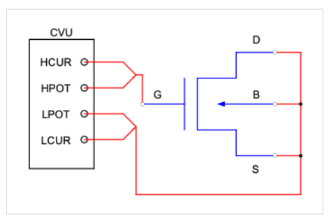
The circuit diagram for this test is shown in Figure 17. The Gate terminal of the MOSFET is connected to HCUR/HPOT and the Drain/Source/Bulk terminals are connected to the LCUR/LPOT.
To begin, right click within Visual Studio Code’s Explorer pane and select New File. Name the file C_V_sweep_gpib. py or something similar. Unlike the previous two examples that use KXCI commands for the SMUs, the CVU commands do not have the capability to output a graph directly onto the KXCI interface. As a workaround, this example uses the functionality of Microsoft Excel to plot the data directly from a csv file that is outputted. The code for this example is shown below, and it may be copied and pasted. Ensure that the instrcomms.py file is in the project folder, such that it may properly be imported into the test that is being created.
Example Code #3: CVU GPIB Example
import time from instrcomms import Communications
import csv
INST_RESOURCE_STR = "GPIB0::17::INSTR" # instrument resource string, obtained from NI-VISA Interactive
my4200 = Communications(INST_RESOURCE_STR) # opens the resource manager in PyVISA with the corresponding instrument resource string
my4200.connect() # opens connections to the 4200A-SCS
my4200.write("DR1")
my4200.write(":CVU:RESET")
my4200.write(":CVU:MODE 1")
my4200.write(":CVU:MODEL 2")
my4200.write(":CVU:SPEED 2")
my4200.write(":CVU:ACZ:RANGE 0")
my4200.write(":CVU:FREQ 1E6")
my4200.write(":CVU:SWEEP:DCV 5, -5, -0.2")
my4200.write(":CVU:DELAY:SWEEP 0.1")
my4200.write(":CVU:TEST:RUN")
time.sleep(20) # time needed for test to finish
CpGp = my4200.query(":CVU:DATA:Z?") # queries readings of Cp-Gp
Volt = my4200.query(":CVU:DATA:VOLT?") # queries readings of Voltage
sep = ‘;’ # separator between Cp-Gp
VoltList = Volt.split(‘,’) # splits voltage list at commas
CpGpList = CpGp.split(‘,’) # splits Cp-Gp list at commas
CapList = [] # list only for capacitance values
for z in CpGpList: # separates the Cp-Gp list into only the Cp values, by removing the value after the semi-colon
CapList.append(z.split(sep, 1)[0])
zipped_list = zip(VoltList, CapList) # creates iterable zipped list
columns = [‘Voltage (V)’, ‘Capacitance (F)’] # column headers
with open(‘output.csv’, ‘w’, newline=’’, encoding=’utf-8’) as f: # opens and writes csv file
writer = csv.writer(f)
writer.writerow(columns)
writer.writerows(zipped_list)
f.close() # close stream
my4200.disconnect() # close communications with the 4200A-SCS
This code receives the output data from the test and stores it into a Python list. It then uses the csv Python library to write the output data to a csv file. Descriptions of each of the KXCI commands that are used in this example are shown in Table 2.
| KXCI Command | Description |
| BC | Clears all readings from the buffer |
| DR1 | Enables service request for data ready |
| :CVU:RESET | Resets CVU to default settings |
| :CVU:MODE 1 | Sets CVU to system mode |
| :CVU:MODEL 2 | Sets CVU to Cp-Gp model |
| :CVU:SPEED 2 | Sets CVU to quiet speed mode |
| :CVU:ACZ:RANGE 0 | Sets AC measurement range to auto |
| :CVU:FREQ: 1E6 | Sets AC frequency to 1MHz |
| :CVU:SWEEP:DCV 5, -5, -0.2 | Configures DC voltage sweep from 5V to -5V, with -0.2V steps |
| :CVU:DELAY:SWEEP 0.1 | Sets sweep delay to 0.1s |
| :CVU:TEST:RUN | Starts the CVU test |
| :CVU:DATA:Z? | Queries the Z measurement, being Cp-Gp with this CVU model |
| :CVU:DATA:VOLT? | Queries the voltage measurement on the CVU |
Table 2. KXCI command list for CVU sweep GPIB example.
The command :CVU:DATA:Z? queries the Z measurement of the CVU based off of the set CVU model. Since this example is using model 2 of the CVU, this command will return the Cp-Gp measurements, which is the measured parallel capacitance and conductance model. The format in which the command returns the data is the following: Cp1;Gp1,Cp2;Gp2,… Cp1;Gp1 is the first capacitance and conductance measurement, Cp2;Gp2 is the second, and so on. Since this example performs a C-V sweep, the Gp measurement is not needed. As seen in the code for this example, the Cp-Gp measurement data is split such that only the Cp measurement remains. It removes everything after the semicolon in each pair of measurements and then appends only the Cp value to a new list.
Once the code is executed by pressing Run Python File in the top right of Visual Studio Code, an output csv file is created within the directory where Python is configured on the PC. This file contains all the data points needed for a capacitance and voltage plot. An example resulting graph is shown in Figure 18. Note that the graph will not automatically be created, it must be done manually within Microsoft Excel or another similar application.

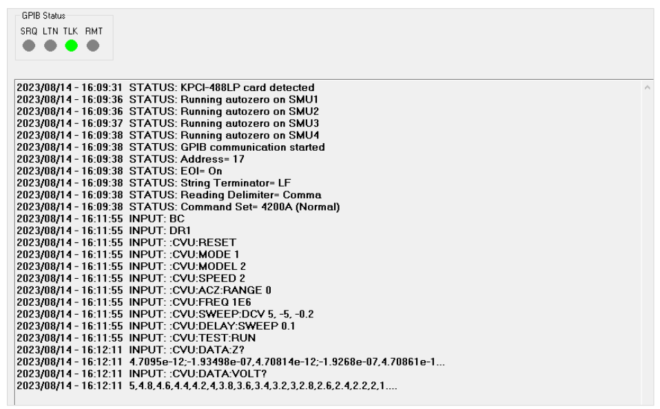
A successful run will also show a small selection of measured values directly on the KXCI interface. This can be a tool to determine if the test was configured properly based on the resulting values. The KXCI interface for this test is shown in Figure 19.
Conclusion
The Keithley 4200A-SCS Parameter Analyzer is a powerful tool to easily perform automated tests on devices. Using Python with Visual Studio Code and the KXCI interface enables users to control each of the instrument modules within the 4200A-SCS. To see a full list of available KXCI commands and respective descriptions, see the document Model 4200A-SCS KXCI Remote Control Programming.
Find more valuable resources at TEK.COM
Copyright © Tektronix. All rights reserved. Tektronix products are covered by U.S. and foreign patents, issued and pending. Information in this publication supersedes that in all previously published material. Specification and price change privileges reserved. TEKTRONIX and TEK are registered trademarks of Tektronix, Inc. All other trade names referenced are the service marks, trademarks or registered trademarks of their respective companies.
050924 1KW-74006-1