
Low-Noise Measurements with QuietChannel Technology on the 7 Series Oscilloscope
If you’ve ever tried to measure high-speed signals over real-world channels, you know the struggle. Lossy cables, fixtures, and connectors all blur the signal before it reaches your oscilloscope. That’s why engineers turn to de-embedding—a mathematical process that removes channel effects so you can see the signal as if it came straight from the transmitter.
But here’s the catch: while de-embedding restores lost high-frequency content, it also amplifies oscilloscope noise. Think of it like sharpening a blurry photo—you recover detail, but the grain and static get magnified, too. For compliance tests and design validation, that added noise can make the difference between a passing eye diagram and a costly redesign.
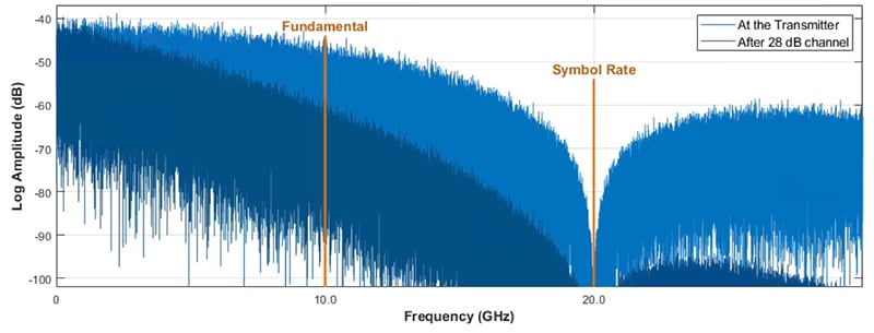
Figure 1: Frequency content of a 20 Gb/s PRBS signal before and after channel loss.
Why Traditional De-Embedding Amplifies Noise in Oscilloscope Measurements
Modern oscilloscopes already work hard to keep their noise floors low, but when you apply a de-embed filter, both the signal and the oscilloscope’s noise get boosted together. The result? Cleaner edges aren’t as clean as they should be, and jitter measurements can be misleading.
For short traces, this may only cost you a few percent of margin. But as data rates climb and channels stretch, noise amplification can make your carefully de-embedded eye diagrams collapse, hiding the truth about your design’s performance.
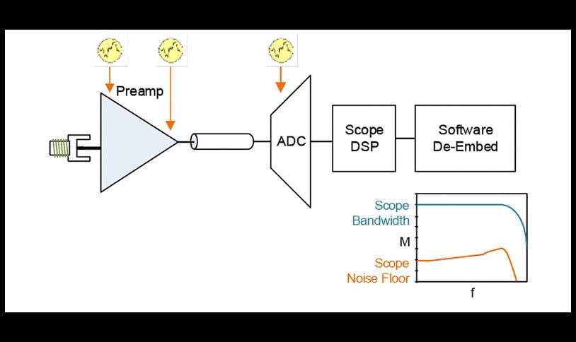
Figure 2: Traditional oscilloscope signal path with software de-embed.
QuietChannel Technology: Reducing Noise Floor for Accurate Oscilloscope Measurements
Tektronix engineers recognized that the bottleneck wasn’t just the channel—it was how the instrument handled noise when de-embedding.
That’s why the 7 Series DPO oscilloscope introduced QuietChannel™ technology, a patented blend of hardware and DSP that shapes the scope’s noise floor instead of letting it grow unchecked.
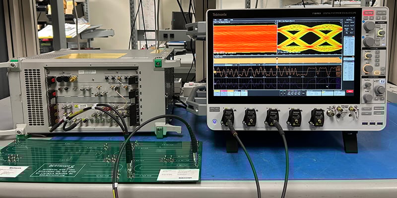
Test setup: A BERT scope (left) is used to drive PRBS test signals through channel of different lengths. The 7 Series DPO with QuietChannel technology is used to measure the resulting signal.
Here’s how it works:
- The oscilloscope’s preamp applies a form of continuous-time linear equalization (CTLE) to boost high-frequency components before digitization.
- After the ADC, the DSP reverses that equalization for a flat frequency response.
- This technique leaves the signal intact while shaping the noise floor so it stays lower at higher frequencies.
The result is like putting on a pair of noise-canceling headphones for your oscilloscope —suddenly, the de-embedded waveform is clearer, with less jitter and more trustworthy margins.
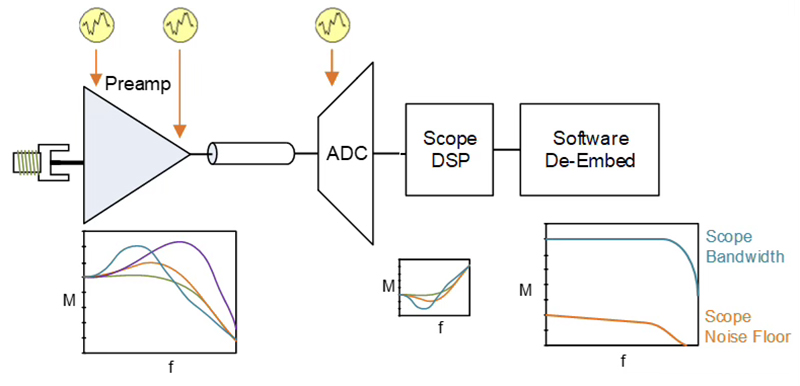
Figure 3: Oscilloscope noise with de-embed and QuietChannel technology.
Experiment Results: Eye Diagrams, Jitter and SNR Improvements
Tektronix ran a series of experiments to show the impact of QuietChannel technology across different channel lengths:
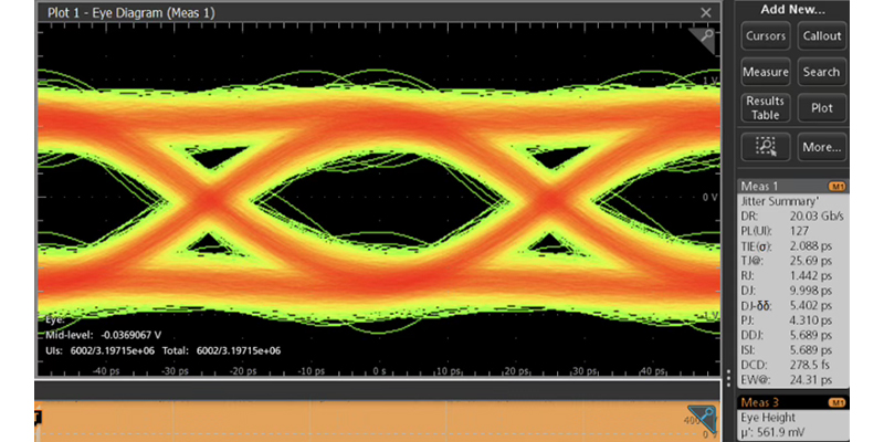
- 17-inch trace, 20 Gb/s data – A modest 3% increase in eye height and 1% eye width. Small, but enough to swing compliance results in your favor.
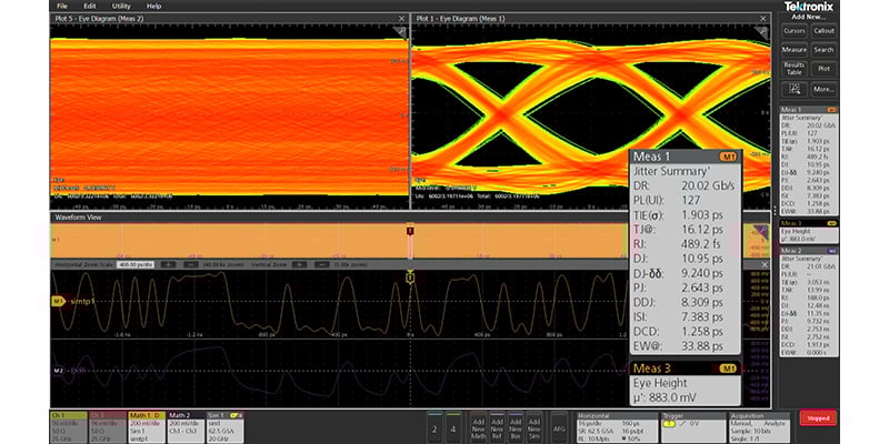
Figure 4: 20 Gb/s with QuietChannel technology through 17-inch trace. Eye height has increased by 3%.
- 24-inch trace – Eye height jumped 34% and eye width widened 31%. Even more dramatic, random jitter dropped by nearly 40%—from 1.4 ps to just 860 fs.
- 31-inch trace, 16 Gb/s data – Eye height more than doubled, with a 5 dB improvement in signal-to-noise ratio at higher frequencies.
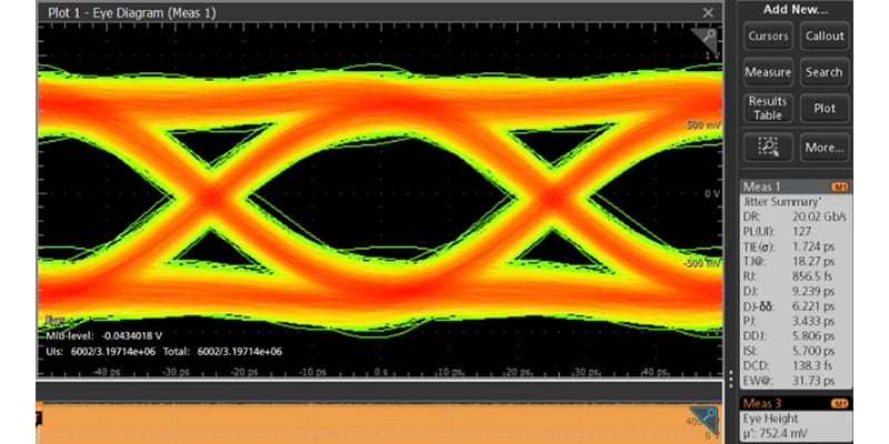
Figures 5 & 6: 20 Gb/s de-embed of the same 24-inch trace. The eye diagram on the left was measured without QuietChannel technology and shows random jitter (RJ) of 1.4 ps. The eye diagram on the right was measured with QuietChannel technology and shows RJ of about 860 fs.
In other words: the longer and lossier your channel, the more QuietChannel technology helps.
Benefits of QuietChannel Technology for Engineers
For compliance testing, these improvements mean higher confidence that your DUT passes when it should—and fails when it must. For design validation, it means faster debug, fewer false failures, and better yield at production.
Instead of fighting against noise in your measurement system, you can finally see the real behavior of your signal.
Bringing Accuracy and Clarity to High-Speed Testing and Debugging
QuietChannel technology isn’t just another filter—it’s a rethinking of how oscilloscopes manage noise in the face of de-embedding. By reshaping the noise floor itself, the Tektronix 7 Series DPO makes lossy channel testing more accurate, more reliable, and more engineer-friendly.
If you’re working with 16, 20, or even 28 Gb/s serial links, QuietChannel technology could be the margin of clarity you’ve been missing.