Adaptive Power Optimization is Revolutionizing PMICs
“There is no better way to save energy and cut bills than by turning all electronic devices off.”
This basic piece of advice is the underlying principle and philosophy behind any form of energy management applied to energy consumption optimization, and in general in so-called adaptive power optimization.
In the case of battery powered electronics, once the best possible supplier for battery cells is selected and integrated into the design, it’s then a PMIC’s job to boost its duration to the maximum.
To do that, there is no better way than keeping the connected circuitry operating at the minimum loads possible.
With this principle in mind, embedded portable electronics engineers can program their power management control system to source 3.6V at the output voltage connector for as long as possible while precisely estimating (and potentially avoiding) any harmful conditions. This includes a situation where current absorption causes voltage levels to drop beneath the “red threshold”, which means it is no longer able to sustain the loading circuit.
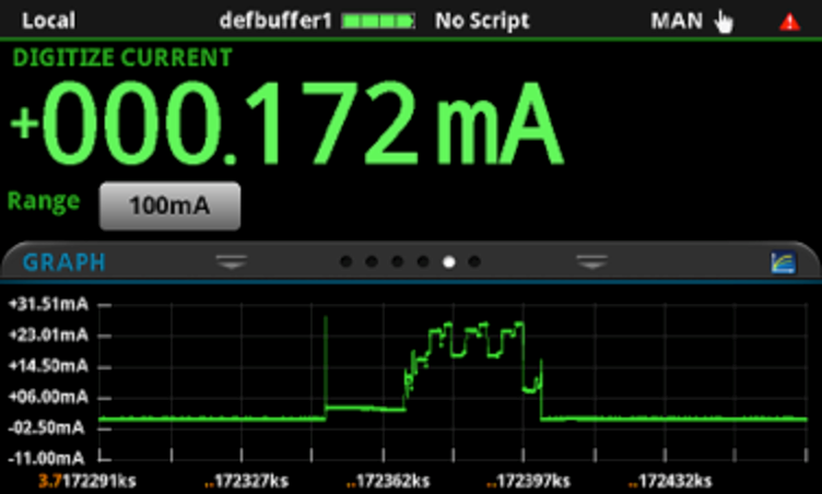
Figure 1: Typical current profile of an IoT device under various operating conditions
In modern PMICs, the circuitry inside readjusts to constantly maintain two specific conditions:
- Adapting to load configuration so that the highest output power can be supplied
- Intelligent distribution of energy by predicting working conditions
Control loop algorithms must carefully detect load change conditions, such as rapid current peaks due to load falls.
Power converter regulation includes detecting such conditions and applying a countermeasure on the circuit topology around power MOSFETs, so that the operating frequency is adjusted in a controlled way, i.e., the path that leads to minimum efficiency loss.
This is an “art of electronics” job, with controlled communication signaling flow and readjusting its parallel configuration between various phases of the conversion.
The Need for Essential Instrumentation
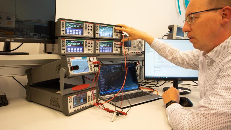
Figure 2: A typical test bench with automation software for portable battery-operated device characterization
To test PMICs, there are essential bench instruments that must be in your lab. These instruments will enable designers to reproduce real-life scenarios as closely as possible.
Think about energy source (battery) voltage and resistance changes, or the load variations just discussed. If you have a good multimeter to monitor the signals in a circuit while reproducing all the sourcing and load conditions, this would be the ideal companion for the evaluation kit you are working on if the multimeter is compact enough that there is still space for your laptop.
Since your laptop is needed to run the simulation software for compiling (and recompiling) in your PMICs, it would be an additional benefit if that instrument came with an automation software companion add-on to log, trace, report, and easily and accurately apply multiple instrument setups. Even better would be if the software application removed any programming burden and offered the engineer what is really needed to get the job done.
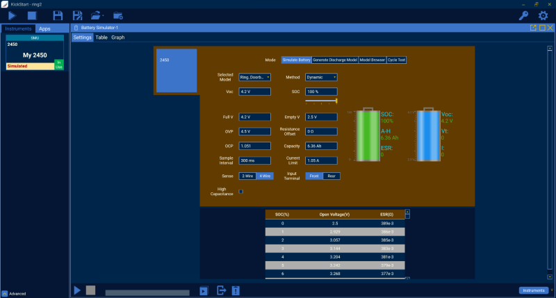
Figure 3: Screenshot of KickStart control software simulating a battery profile
Keithley SourceMeters and KickStart Software
A Keithley SourceMeter™ can be set as a voltage source to set a battery specific rate with the desired charging current set as the current limit and used as a constant current source to charge the battery until the programmed voltage level is reached. The SMU can also be set to operate as a sink, thus “dissipating” power. The current is absorbed by the SMU from the battery while tracking the discharge current flowing in.
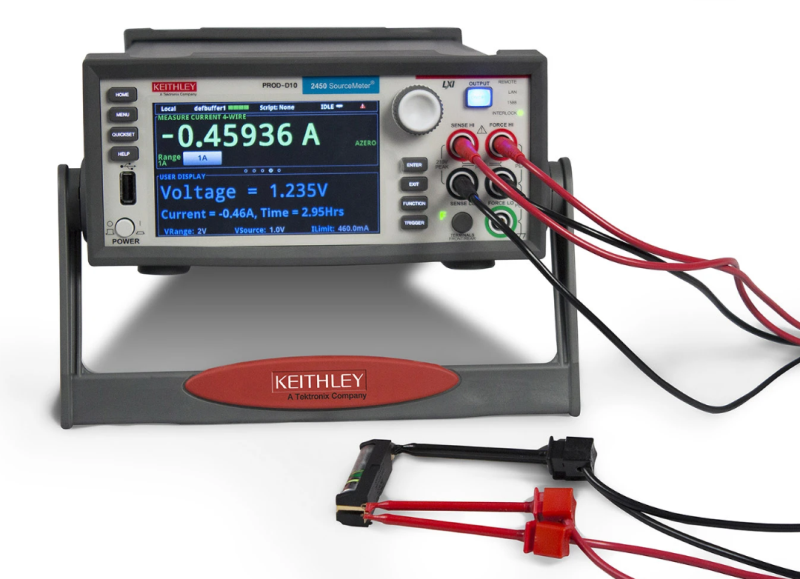
Figure 4: Keithley SMU cycling a Lithium-Ion battery
Charging and discharging cycles can be automated using scripts which control the unit via the supported communication interfaces for the instrument or by using specific software applications.
The SourceMeter™ can measure the battery voltage while it is charging or discharging, as well as the current flowing in and out, creating voltage and current profiles versus time, which is precious data to determine whether adaptive power optimization is working as expected.
In order to simplify test setup and eliminate programming time, we recommend Keithley KickStart Software, which supports the entire Keithley SMU portfolio as well as all DMMS, DAQs, Power Supplies, some Tektronix AFGs and most Tektronix Oscilloscopes.
Why Now?
There is no better time than now to consider a Keithley Graphical SMU to set up your PMIC test bench. For a limited time, Keithley is offering a special promotion running through December 31, 2023. With an eligible hardware purchase, you get six-months’ free access to the full KickStart Software suite. Additionally, Keithley’s KickStart Software specialty Battery Simulator App can accelerate battery modeling, battery simulation and emulation, and battery cycle testing, and can be trialed for 30 days free and purchased thereafter to unlock the full potential of your development test bench.
For those interested about this promotion based in Europe learn more on this page, for readers based in this United States learn more on this page.