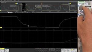
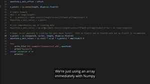
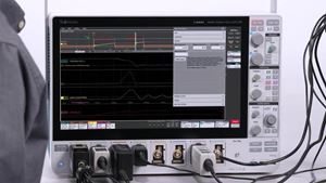
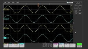
This explains how to use an oscilloscope equipped with control loop response measurement capability to measure the frequency response (Bode Plot) of a power supply control loop.
A Bode plot is graph of the frequency response of a system, characterizing gain and phase shift across different frequencies.
A modulating signal is injected into the feedback loop. The modulating signal and the output of the control loop can then be ratioed to calculate gain and compared in time to find phase.
Source:
- Arbitrary/Function Generator (built into 6 Series MSO)
- Picotest J2101A Injection Transformer
Measure:
Videos recorded by:
Tony Ambrose, Application Engineer, Tektronix
Steve Sandler, Founder, and CEO of PICOTEST.com
기간 01:39


