연락처
텍트로닉스 담당자와 실시간 상담 6:00am-4:30pm PST에 이용 가능
전화 문의
9:00am-6:00PM KST에 이용 가능
다운로드
매뉴얼, 데이터 시트, 소프트웨어 등을 다운로드할 수 있습니다.
피드백
Synchronizing Parallel Testing with the MP5000 Series

Synchronizing Parallel Testing with the MP5000 Series
Introduction
Growth in the semiconductor chip market, driven by the rapid advancements in AI and the widespread shift toward electrification, has required manufacturers to increase throughput on testing and validation without sacrificing test accuracy. One way to achieve this is to test devices in parallel or at the same time. Once a test routine is verified, it must be duplicated to meet the production requirements. This introduces new challenges, including time synchronization between channels and additional cost of scaling.
The Tektronix MP5000 Series Modular Precision Test System is designed to meet parallel testing needs. The high density 1U mainframe, model MP5103, can be equipped with 3 modular source measure units (SMUs) and/or power supply units (PSUs) for up to 6 independent channels. The MP5103 supports Test Script Processor (TSP), which makes expansion easy through TSP-Link ™ to connect up to 32mainframes. This application note focuses on synchronizing 6 channels in parallel for standard semiconductor and optical characterization tests.
New Trigger Model, New Testing Possibilities
The key to precisely timed parallel testing is the trigger model, which coordinates the actions of each instrument channel. Traditional instruments use fixed trigger models with a particular order of actions and minimal control over handshaking. These models are limited and difficult to program when a test needs more than one channel.Instruments with no trigger model or more flexible trigger models are easy to program but often cannot provide precising timing between steps in the test. This creates unneeded delays in test time or damaging devices due to improper test conditions.
The MP5000 series leverages the best features of legacy performance and flexibility to create a newTriggerFlow® trigger model. The trigger model is completely customizable, following a block flow chart style. Users can control the actions and settings of the instrumentation in any order within the trigger model. Various delay and notify blocks achieve precise timing and handshaking between channels without the need for complex external triggering code.
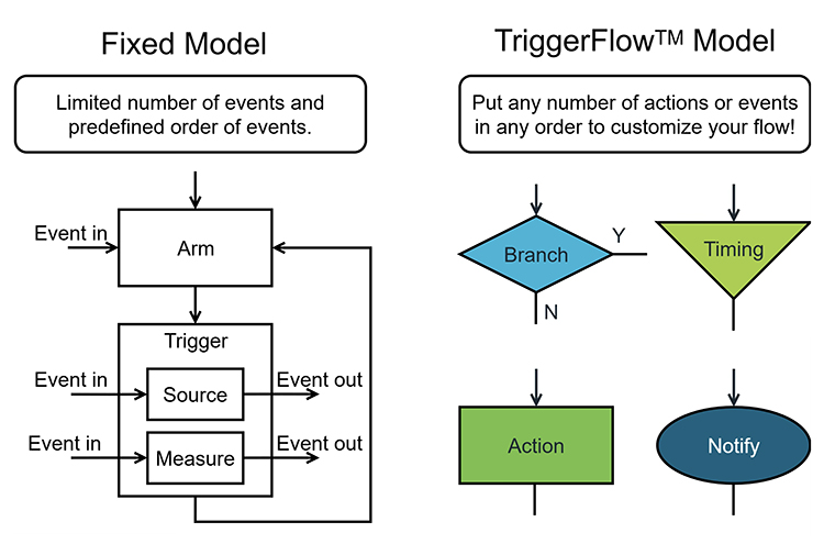
Figure 1: TriggerFlow has 4 block types to customize your test flow over a fixed model
With the TriggerFlow trigger model, you need only a few steps to go from idea to execution:
- Plan: Determine the desired test routine, including instrument settings, sweep configurations, number of channels needed and timing.
- Expand: Create a flow chart for each channel in the test. Expand the steps to match available trigger model blocks for the MP5000.
- Build: Replace the blocks in the flow chart with code to build the trigger model. Program events and delays for precise timing.
The following sections walk through examples of synchronizing channels in parallel and how to build the TriggerFlow model.
Example: 2 Channel MOSFET Family of Curves
Characterizing the output behavior of a MOSFET requires a minimum of 2 SMU channels, one stepping voltage biases on the gate terminal and measuring output and the other sweeping voltage on the drain terminal and measuring current. This test sequence is shown in Figure 2. The blue blocks represent measurement points and the green dotted arrows represent points of synchronization. The drain channel alerts the gate channel to start and then as the drain sweeps, there is a notification of when measurements start and end to coordinate the sweeping. At the end of the sweep, the drain must tell the gate to move to the next step.
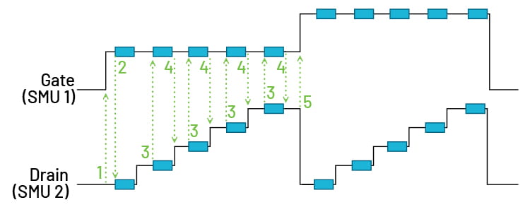
Figure 2: MOSFET Family of Curves Test Sequence
Traditionally this must be programmed using nested for loops, to repeat the drain sweep at each voltage step on the gate. Each action is performed sequentially, leading to longer test times. The MP5000 simplifies this using both channels of a single MSMU60-2 module. The TriggerFlow models are shown in Figure 3, where channel 1 is connected to the gate and channel 2 is connected to the drain.
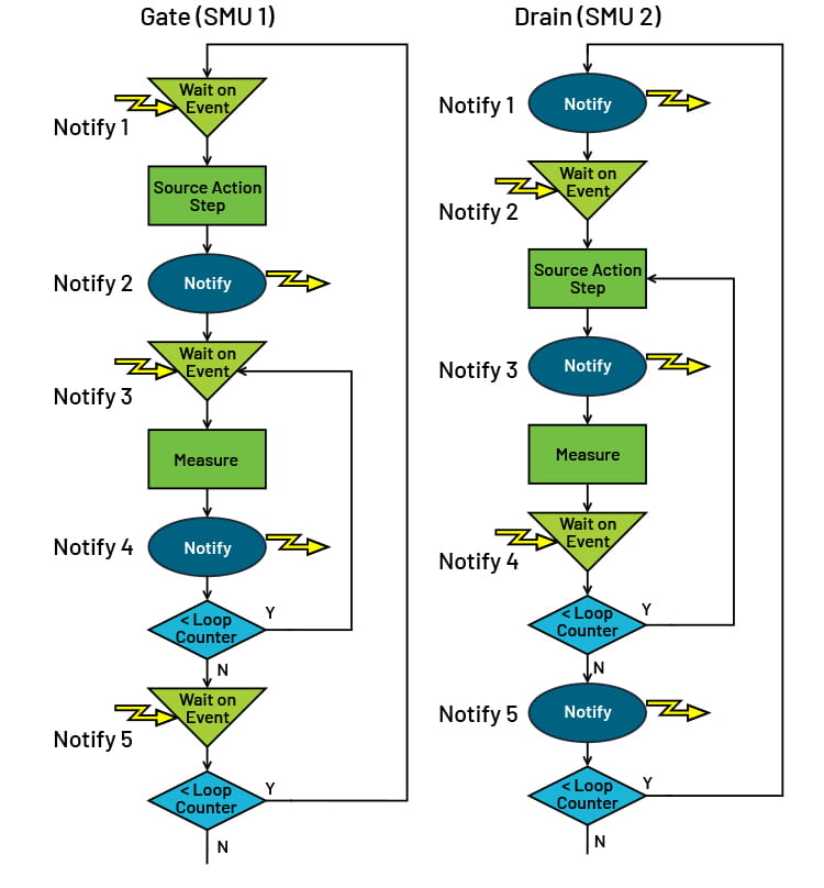
Figure 3: MP5000 Trigger Models for Drain Family of Curves on a MOSFET
When one action depends on another, such as the drain sweep starting once the gate voltage has switched, a notify-wait block pair is used. When one action completes,the trigger model executes a notify block. This signal can be routed to other events, or directly to a wait block in another trigger model that is paused until the event is received.This allows one trigger model to begin executing blocks as soon as another trigger model finishes with no latency. The models continue to operate in parallel until there is another time control block.
Branch blocks are used when a model needs to repeat actions or make a decision during testing. In the case of the MOSFET, the branch block is used to loop over the blocks generating the sweep and taking the measurement, reducing that portion of the test to a set of 3 blocks.
An additional notify block can be used to synchronize measurements on the gate at the same time as the measurement on the drain.
Figure 4 shows the output of this trigger model sequence as captured on a scope. The gate waveform (top) is exactly synchronized with the drain sweep (middle) with no significant delays in time.
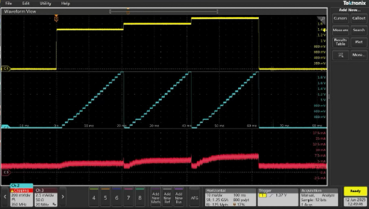
Figure 4: Output of MOSFET Family of Curves test, Gate Voltage (top), Drain Voltage (middle) and Drain Current (bottom).
Example: 2 Channel VCSEL LIV Characterization
Characterizing light-current-voltage (LIV) behavior for optical devices such as LEDs, lasers and VCSELs, requires instrument channels to be controlling separate devices but still tightly synchronized. Here, an SMU channel sweeps forward current and measures voltage on a laser diode while a second channel measures the current detected by a separate photodiode. Many of these tests require pulsed signals to prevent thermal effects, so the photodiode measurement must be made at the right time, when the laser diode is on or outputting consistently. This test is shown in Figure 5.
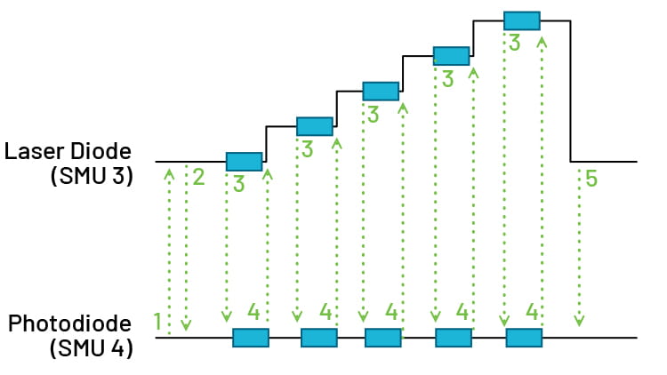
Figure 5: LIV Characterization for Photodiode and Laser Diode Pair
In TriggerFlow, this test converts to 2 trigger models, one sourcing and measuring and the other measuring only. Notify-wait blocks again are used to coordinate when actions are complete and branch blocks repeat sections to execute the sweep. An additional constant delay block is included to provide additional time before the measurement is taken. The trigger model for this test is shown in Figure 6.
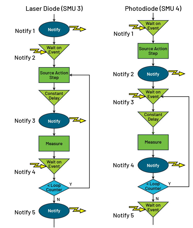
Figure 6: MP5000 Trigger Models for LIV Characterization
When this is executed, the resulting waveform shown in Figure 7 displays a typical forward voltage characteristic of a diode (top) and the resulting measurement of the current in the photodiode (bottom). Again, the waveforms are synchronized with no extra gaps or delays in measurement.
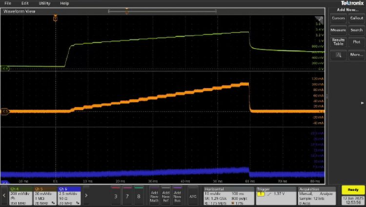
Figure 7: Output of LIV Trigger Model, Laser Diode Voltage (top), Laser Diode Current (middle), Photodiode Current (bottom)
Example: 6 Channel Synchronization
Synchronized parallel testing can involve every channel or set of channels running the same test or running separate tests that must start at the same time as each other or rely on the actions of one to direct the another. We can combine the previous two examples with simple sourced waveforms on 2 additional SMU channels and start all 6 channels at the same time by adding a wait block to the beginning of every model. The entire parallel test is shown in Figure 8.
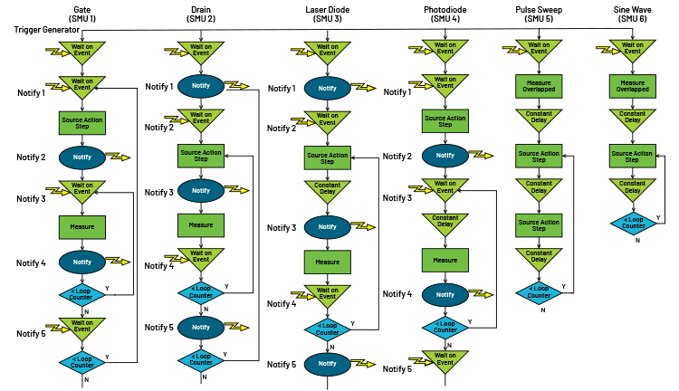
Figure 8. 6 Trigger Models to Operate in Parallel
The fifth model conducts a pulsed sweep using the source action blocks to change the output level and the delay constant block to time the pulses. The sixth model generates a sine wave using source action step and delay constant blocks. Both models start measurements at the beginning of the output using the measure overlapped block. This allows the SMU to measure in the background while continuing to execute blocks in the trigger model, essentially using the high-speed digitizer to capture the output waveform. Neither of these models use notify-wait block combinations because they are each operating independently from other channels. They are only synchronized at the start point.
The resulting execution captured on an oscilloscope in Figure 9 shows each of the channels starting at the same time and executing in parallel.
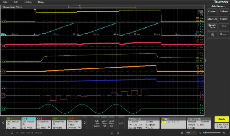
Figure 9: 6 Channel Execution Captured on Scope
Graphing data captured by the SMU channels in a GUI dashboard developed in Python is shown in Figure 10. This replicates characterization tests that would be displayed on a device datasheet. Code to execute this example is provided on the Tektronix Github.
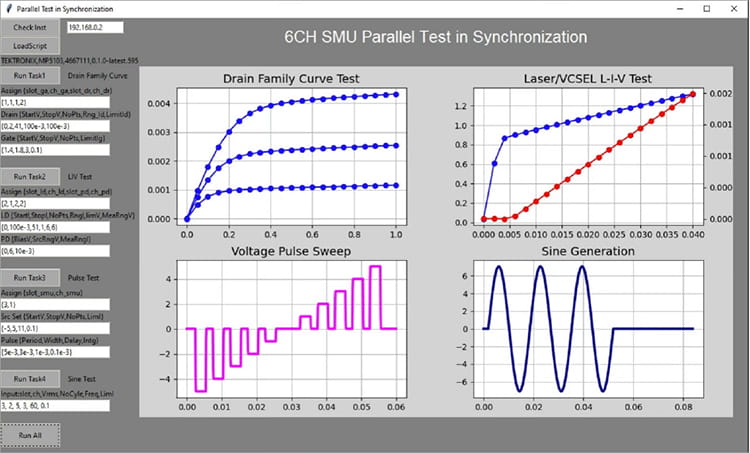
Figure 10: Measured Data from 6 Channels Graphed in Python
Conclusion
This example demonstrated running 6 channels in parallel, executing 4 independent tasks that each required different actions and levels of synchronization. This parallel test application can be further expanded to additional mainframes through the use of TSP-Link™ to synchronize trigger models. The MP5000 Modular Precision Test System is designed for high density and test throughput by using a customizable, user-friendly trigger model. This provides the flexibility needed to create a best fit automated test system from validation to production.