연락처
텍트로닉스 담당자와 실시간 상담 6:00am-4:30pm PST에 이용 가능
전화 문의
9:00am-6:00PM KST에 이용 가능
다운로드
매뉴얼, 데이터 시트, 소프트웨어 등을 다운로드할 수 있습니다.
피드백
Measuring the Electrical Resistivity of Insulating Materials

Measuring the Electrical Resistivity of Insulating Materials
Introduction
Electrical resistivity is a basic material property and defines how well the material will conduct an electric current. Insulators are poor conductors of electrical current and typically have a high resistivity in the range of 109 to 1020 ohm-cm. The electrical resistivity of an insulator is determined by measuring resistance, then converting it to resistivity by taking geometric considerations into account.
The resistance of an insulating material is measured by applying a known potential to the sample and measuring the resulting current. Because the measured current is very low, usually in the nanoamp or picoamp range, an electrometer is often used. The Keithley 6517B Electrometer/High Resistance Meter is commonly used to make these measurements because of its ability to force voltage up to ±1000 V DC and measure very small current (<3 fA input bias current) and high resistances (up to 1018 Ω).
To account for the sample’s geometry, electrodes with convenient dimensions should be used to make contact to the sample. The electrode configuration depends upon whether the volume or surface resistivity is measured. The Keithley 8009 Resistivity Test Fixture can be used for either volume or surface resistivity measurements on insulating materials.
This app note explains how to make volume and surface resistivity measurements of insulators using the 6517B Electrometer/High Resistance Meter, 8009 Resistivity Test Fixture, and the Kickstart High Resistivity Application that can be used to automate the measurements.
Standard Test Methods
The resistivity of a solid insulating material is usually measured by sourcing a known voltage for a specified time period and then measuring the resulting current. The resistivity is calculated using Ohm’s law, the sample thickness, and the physical dimensions of the electrodes.The specific details of a test procedure including electrode configuration, sample preparation, electrification time, and other details are often described in standard test methods.
Two common standard resistivity test methods for insulating materials include ASTM D-257 “DC Resistance or Conductance of Insulating Materials” and the IEC 62631-1 “Dielectric and Resistive Properties of Solid Insulating Materials”. These standards provide detailed information on calculations, sample preparation, correction factors and other measurement considerations.
The test configurations will vary depending on whether measuring the surface or volume resistivity of the sample.
Surface Resistivity
Surface Resistivity is defined as the electrical resistance of the surface of a material and is expressed in ohms or ohms/ square. It is measured by placing two electrodes on the surface of the test sample, applying a potential difference between them, and measuring the resulting current.
A configuration for measuring surface resistivity using circular electrodes and the 6517B Electrometer is shown in Figure 1. In this example, the Hi terminal of the 6517B V-Source is connected to the Ring Electrode and the Hi terminal of the 6517B Electrometer is connected to the Guarded Electrode. The LO of the Electrometer is the Guard and is connected to the Top Electrode to prevent leakage current from flowing through the material. The 8009 Resistivity Test Fixture uses circular electrodes like the ones shown.
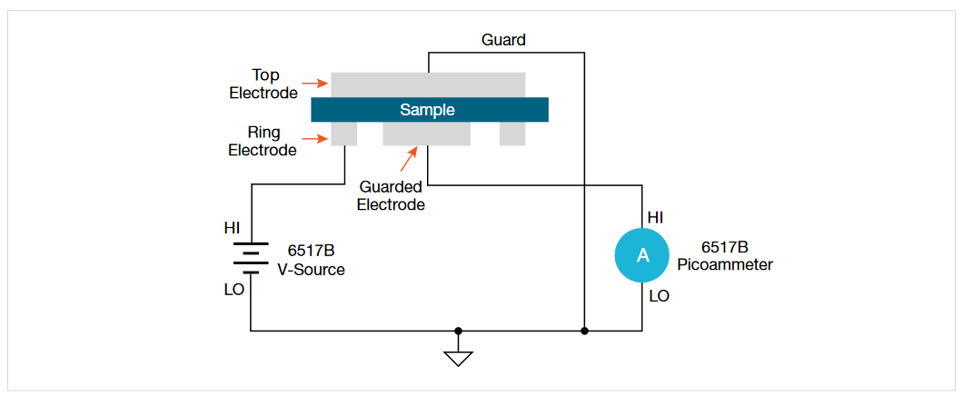
Figure 1. Surface resistivity test configuration using circular electrodes and the 6517B Electrometer
Using this test configuration and referring to the circular electrodes shown in Figure 2, the surface resistivity can be calculated as follows:
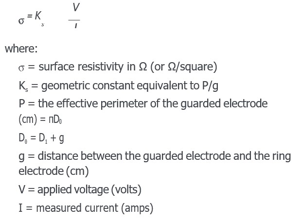
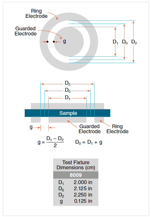
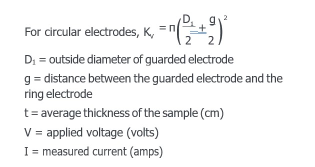
Figure 2. Circular electrode dimensions
If using the Keithley 8009 Resistivity Test Fixture, the diameter of the circular electrodes and gap are shown in inches as follows:
D1 2.000 in
D2 2.125 in
D3 2.250 in
g 0.125 in
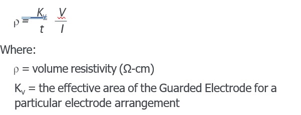
Volume Resistivity
The volume resistivity is a measurement of the leakage current directly through a material. It is defined as the electrical resistance of an insulating material and is expressed in ohm-cm. The volume resistivity is measured by placing the test sample between two electrodes, applying a potential difference between them, and measuring the resulting current using an electrometer, such as the 6517B Electrometer.
A configuration for measuring the volume resistivity of a sample using circular electrodes and the 6517B Electrometer is shown in Figure 3. In this example, the HI terminal of the 6517B V-Source is connected to the Top Electrode and the Hi terminal of the 6517B Electrometer is connected to the Guarded Electrode. The LO of the Electrometer is the Guard and is connected to the Ring Electrode to prevent leakage current from flowing between the Ring and Guarded Electrodes.
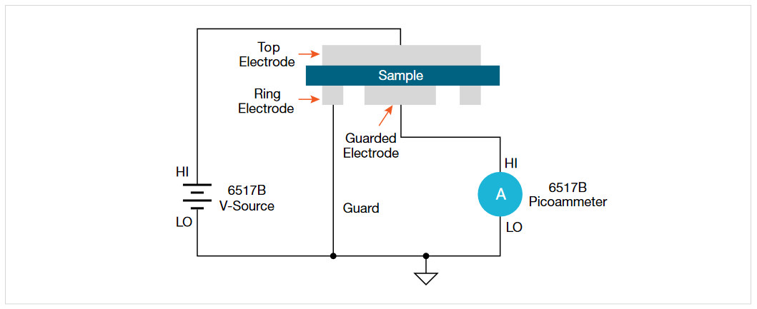
Figure 3. Volume resistivity test configuration using circular electrodes and the 6517B Electrometer
From this example the volume resistivity can be calculated as follows:
Test Parameters and Dependencies
Several factors can affect resistivity measurements of insulators including the applied voltage, electrification time, and environmental factors.
Resistivity measurements of insulators are a function of the applied voltage. Sometimes, the voltage is varied intentionally to determine an insulator’s voltage dependency. Typically, the resistivity decreases as the voltage increases.
The resistivity of insulators also varies as a function of the electrification time. The longer the voltage is applied, the lower the measured current (and the higher the resistivity) becomes because the material continues to charge exponentially. Using an electrification time of 60 seconds is common. When comparing samples, it is always important to use the same electrification time.
Humidity greatly affects the results of surface resistivity measurements and, to a lesser degree, volume resistivity measurements. Moisture will cause the surface resistivity to be lower than normal.
To make accurate comparisons between specific tests, the applied voltage, electrification time, and environmental conditions should be kept constant from one test to the next.
Using the 6517B Electrometer and the 8009 Resistivity Test Fixture
Because of its ability to measure very low current, high resistance, and force up to ±1000 V DC, the 6517B Electrometer/High Resistance Meter is an ideal choice for measuring resistivity of insulating materials. The 6517B has built-in test sequences that enable the user to automatically set-up resistivity measurements and save the results in its internal buffer.
The 8009 Resistivity Test Fixture allows volume resistivity measurements up to 1018 Ω-cm or surface resistivity measurements up to 1017 Ω. The Keithley 8009 Resistivity Test Fixture contains an electrode configuration like the one shown previously in Figure 2. In this test fixture the circular electrodes are in a shielded box to minimize stray electrostatic pick-up, which can cause measurement errors. The electrodes are made of stainless steel and are built to ASTM standards and are compatible with the IEC standard.
The 8009 has conductive rubber electrodes that allow it to make better contact with rigid samples, such as epoxy or ceramics. Refer to the instruction manual for the 8009 for installing the insulator sample in the test fixture. If the 8009 is not suitable for a particular application, then the ASTM procedure also describes several other electrode configurations, depending on the size and shape of the specimen.
Connections between the 6517B and the 8009 are shown in Figure 4. To optimize low current measurements, the ammeter is connected to the test fixture using low noise triax cabling. All of the cables and adapters needed to make the measurements are included with the test fixture.
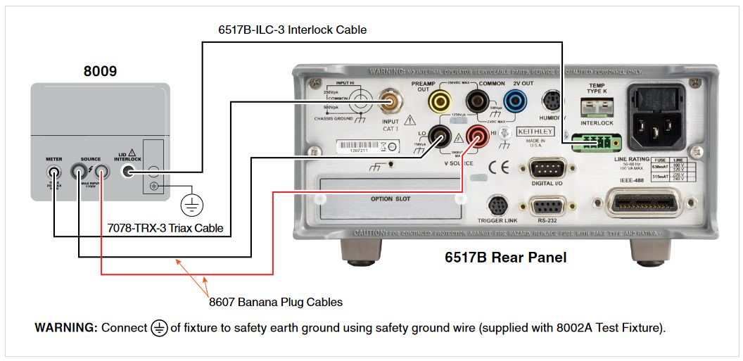
Figure 4. Connections from the 6517B Electrometer to the 8009 Resistivity Test Fixture
Built-In Test Sequences for Resistivity
The 6517B Electrometer includes several built-in test sequences including the Normal Resistivity Tests (based on standard test methods) and the Alternating Polarity Resistance/Resistivity Test. These test sequences can be used to simplify the front panel configuration of these resistivity measurements. Below is an overview of these test methods. Please refer to the 6517B Reference Manual for instruction on using these test sequences.
Normal Resistivity Tests (Surface and Volume)
The normal resistivity tests for both volume and surface resistivity involve applying a voltage bias for a specified period of time (electrification time). At the end of the electrification time, the current is measured and resistivity is calculated using the formulas for surface and volume resistivity that are noted earlier in this document. The user can also choose to discharge the sample for a specified time period. When used with the 8009 Resistivity Test Fixture, the test conforms to the ASTM D-257 and IEC 62631- 3-1 standards.
Alternating Polarity Resistance/Resistivity Test
The Alternating Polarity Resistance/Resistivity test sequence is designed to improve high resistance/resistivity measurements by eliminating the effects of background currents on the sample. Background currents may be due to charge stored in the material, static or triboelectric charge, or piezoelectric effects. If the background current is the same polarity as the measured current, the resultant measured current value will be much higher than the true value. If the background current is the opposite polarity, these unwanted currents could cause a reverse polarity current reading. That is, the current polarity is opposite the polarity of the applied voltage, so the calculated resistance will be negative. To counter these problems, the Alternating Polarity method can virtually eliminate the effects of the background currents on the sample.
The Alternating Polarity method applies a bias voltage of positive polarity, then the current is measured after a specified delay. Next, the polarity is reversed and the current is measured again, using the same delay. The resistance is calculated based on a weighted average of the most recent current measurements. The resistance value is then converted to a resistivity value if the meter has been configured for resistivity measurements. With this method, the user enters the test voltage, measurement time, and the number of iterations. Figure 5 shows an example of the Alternating Polarity test showing the applied voltage and resulting sample current measured as a function of time from a typical high resistance sample.
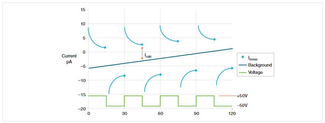
Figure 5. Alternating Polarity test sequence
KickStart High Resistivity Application
Keithley offers software to automate resistivity measurements using both the standard test methods and the alternating polarity method. The KickStart High Resistivity Application performs measurements of volume and surface resistivity of insulators according to ASTM D257 and IEC 62631-3-1 standards. This application is designed for use with Keithley’s 6517B Electrometer/High Resistance Meter and the 8009 Resistivity Test Fixture. However, if the user does not have the 8009, they can enter in their own geometric constants based on their electrodes.
Figure 6 is a screen capture of the Surface Resistivity simplified settings page. The user selects between the surface, volume or resistance measurement types. The measurement mode can be set to step response, normal, or alternating polarity. Other settable parameters include the test voltage, test time, number of readings, current range, and NPLC. Further information on the settings will be described in the following paragraphs.
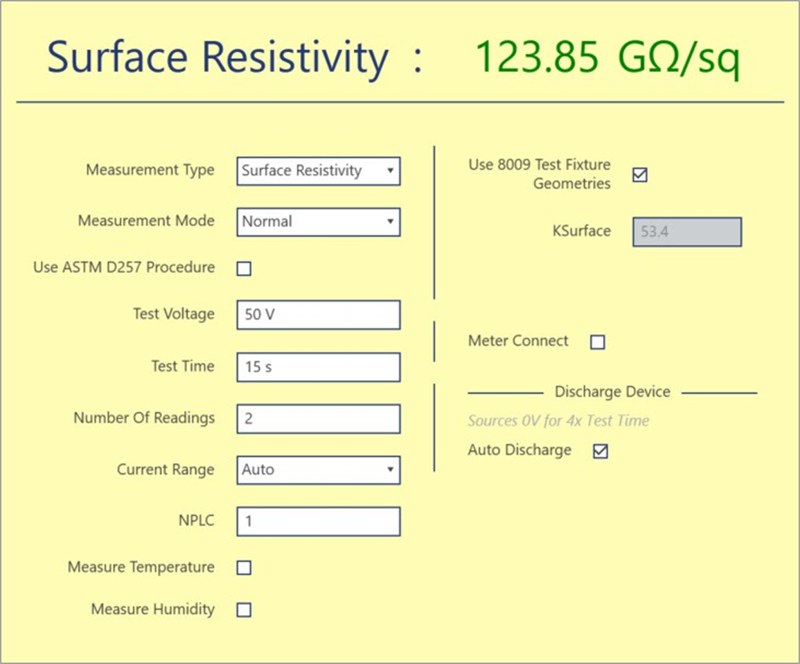
Figure 6. KickStart High Resistivity Application settings page
The KickStart High Resistivity application can be used to:
- Perform a voltage step response to determine an electrification time appropriate to the material’s time constant. Figure 7 is a screen capture from the KickStart software showing both the current and resistivity as a function of time due to a voltage step applied to an insulating material.
- Observe resistivity dependency on temperature and relative humidity using optional 6517-TP and 6517-RH probes.
- Use the alternating polarity technique to eliminate inherent background currents. Figure 8 shows graphs of the alternating polarity technique from KickStart software. The top graph shows the current as a function of time and the bottom graph shows the surface resistivity.
- Perform normal resistivity measurements as a function of time (without alternating polarity) as shown in Figure 9. This normal method complies with ASTM D257 standard as well as IEC-62631-3-1 standards.
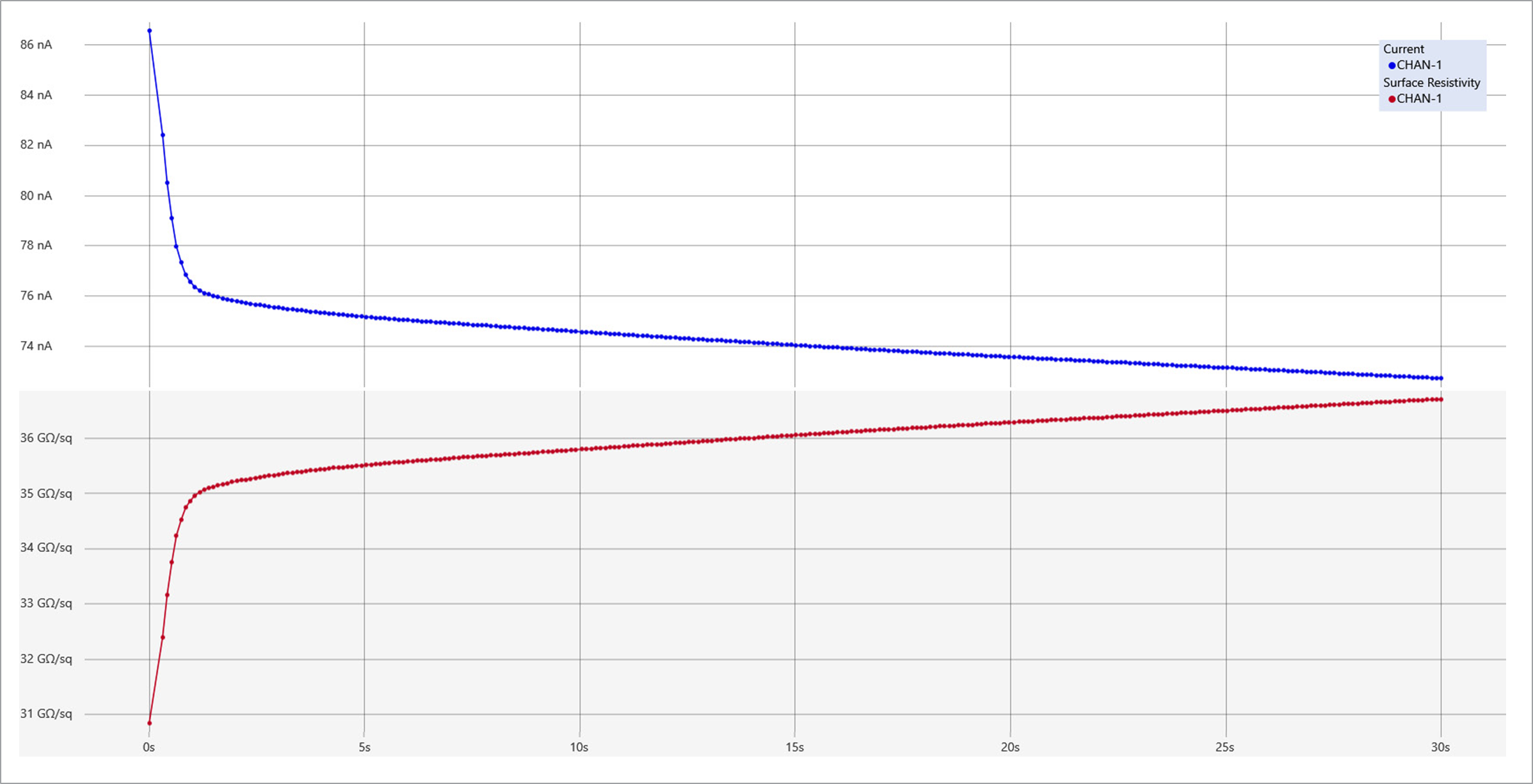
Figure 7. The step response test enables the user to determine the electrification time that will allow current measurements to settle for repeatable resistivity results..
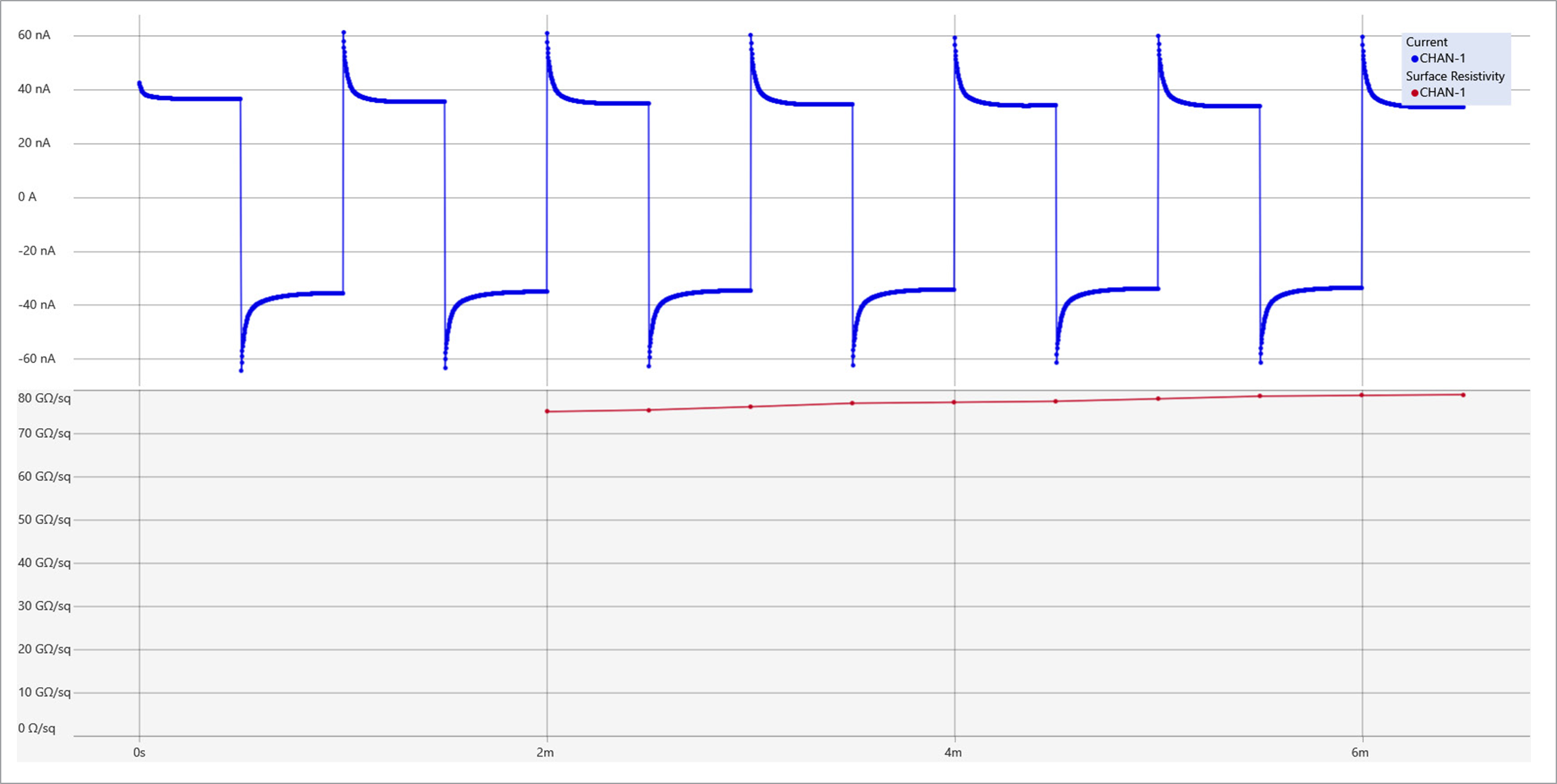
Figure 8. Alternating Polarity method test results displaying current and resistivity as a function of time
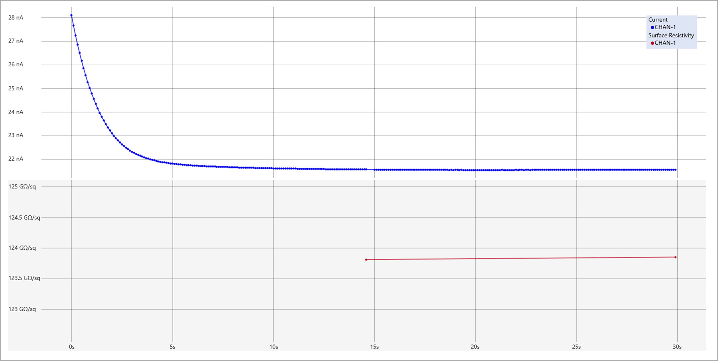
Figure 9. Current and surface resistivity measurements using the Normal (standard) test method
Additional Features of the KickStart High Resistivity Application:
- Has an option to apply voltage and time settings from the ASTM D257 standard (note that voltage specified by IEC-62631-3-1 standard is different, but that user can configure that voltage setting within KickStart).
- Includes the ability to discharge samples after testing. Uses timing values recommended by ASTM D257 standard.
- Exposes 6517B’s meter-connect function in the software to reduce number of external connections user needs to make.
- Returns real-time measurements while step response is executing.
- Consolidates graph data onto one screen for simplified viewing.
- Simplified tabular data display so that users can focus on final resistivity measurement value.
- Take advantage of many built-in KickStart 2.x features including:
- Automatically saves all data to file and allows users to access in Run History
- Allows users to easily compare measurements using Run History compare
- Includes option to automatically export data to file
Download your free trial of the KickStart High Resistivity Application today at www.tek.com/keithley-kickstart.
Ordering information can be found at https://www.tek.com/ keithley-kickstart.