Introduction
A fundamental property of insulators is resistivity. The resistivity may be used to determine the dielectric breakdown, dissipation factor, moisture content, mechanical continuity and other important properties of a material. As an example, the resistivity of the rubber used in automotive tires helps determine its electrostatic discharge safety. Paper manufacturers rely on the resistivity of paper to evaluate how well ink may transfer to the paper in the printing process and how well the paper may run through the printer. The volume resistivity of some insulators, such as sapphire and Teflon®,can be as high as 1016 to 1018 ohm-cm. Because of such large magnitudes, measuring the resistivity of insulators can be difficult unless proper test methods and instrumentation are used. One test method often used for measuring resistivity of insulators is ASTM D-257, "DC Resistance or Conductance of Insulating Materials." Another test method used globally is IEC 62631-3-1 Dielectric and Resistive Properties of Solid Insulating Materials. Measuring insulators involves very low currents, which require special techniques to ensure accuracy and repeatability. The Keithley 6517B Electrometer/HIgh Resistance Meter is commonly used to make this measurement because of its proven ability to accurately measure small currents.
Methods and Techniques
The resistivity of an insulator is measured by sourcing a known voltage, measuring the resulting current, and calculating the resistance using Ohm’s Law. From the resistance measurement, the resistivity is determined based on the physical dimensions of the test sample.
The resistivity is dependent on several factors: (1) applied voltage, (2) electrification time, and (3) environmental conditions such as temperature and humidity. First, it is a function of the applied voltage. Sometimes the voltage may be varied intentionally to determine an insulator's voltage dependence. The resistivity also varies as a function of the length of electrification time. The longer the voltage is applied, the higher the resistivity because the material continues to charge exponentially. Therefore, selecting appropriate test parameters may require some pre-testing.Environmental factors also affect an insulator’s resistivity. In general, the higher the humidity, the lower the resistivity. To make accurate comparisons to a specific test, the applied voltage, electrification time, and environmental conditions should be kept constant from one test to the next. According to the ASTM standard, a commonly used test condition is a voltage of 500 V applied for 60 seconds. According to the IEC standard, apply 100 V for 60 seconds unless another voltage is stipulated.
Depending upon the application, the volume or the surface resistivity, or both, is measured.
Surface Resistivity
Surface resistivity is defined as the electrical resistance of the surface of an insulator material. It is measured from electrode to electrode along the surface of the insulator sample. Since the surface length is fixed, the measurement is independent of the physical dimensions (i.e., thickness and diameter) of the insulator sample.
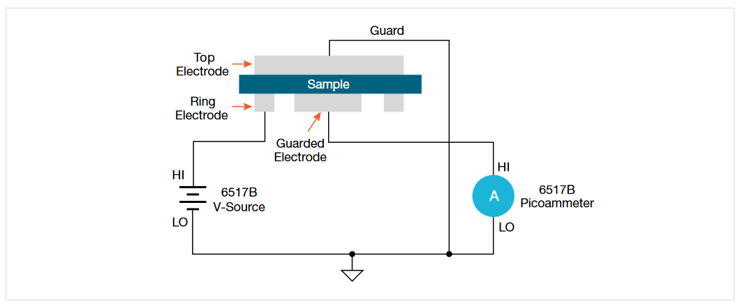
Surface resistivity is measured by applying a voltage potential across the surface of the insulator sample and measuring the resultant current as shown in Figure 1. The 6517B automatically performs the following calculation and displays the surface resistivity reading:
ρS = KSR
ρS = surface resistivity (per square)
R = measured resistance in ohms (V/I)
KS = P/g
where:
P = the effective perimeter of the guarded electrode (mm)
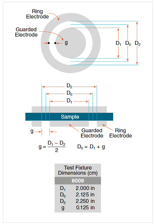
g = distance between the guarded electrode and the ring electrode (mm). Refer to Figure 2 to determine dimension g.
For circular electrodes:
P = ωD0
D0 = D1 + g (refer to Figure 2 to determine dimension D0).
Volume Resistivity
Volume resistivity is defined as the electrical resistance through a cube of insulating material. When expressed in ohm-centimeters, it would be the electrical resistance through a one-centimeter cube of insulating material. If expressed in ohm-inches, it would be the electrical resistance through a one-inch cube of insulating material.
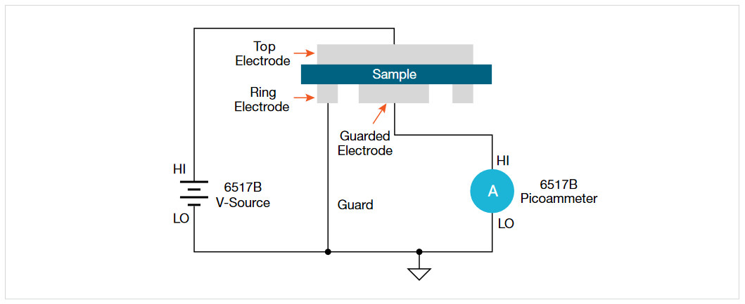
Volume resistivity is measured by applying a voltage potential across opposite sides of the insulator sample and measuring the resultant current through the sample as shown in Figure 3. The 6517B automatically performs the following calculation and displays the volume resistivity reading:
| KV | R |
| τ |
ρV = volume resistivity
KV = the effective area of the guarded electrode for the particular electrode arrangement employed.
τ= average thickness of the sample (mm)
R = measured resistance in ohms (V/I)
For circular electrodes:
| D1 | + | B | g |
| 2 | 2 |
D1 = outside diameter of guarded electrode
g = distance between the guarded electrode and the ring electrode
B = effective area coefficient
Notes:
- Refer to Figure 2 to determine dimensions D1 and g.
- An effective area of coefficient (B) of 0 is typically used for volume resistivity.
Instrumentation
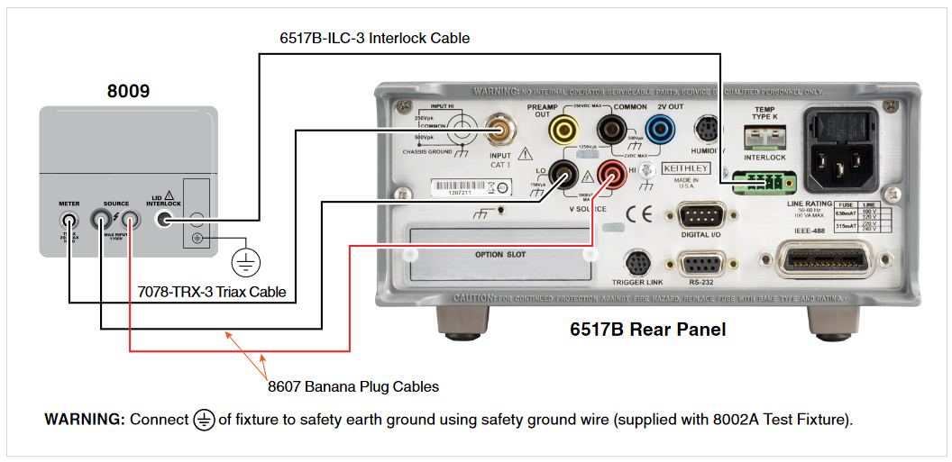
As discussed, these measurements are made using an electrometer or picoammeter, voltage source, and a resistivity chamber, as shown in Figure 4. The 6517B Electrometer includes a 1000 V voltage source that can be used for this application. The 6517B and its predecessor, the 6517A,have a long history in making quality insulation resistivity measurements. The Keithley 8009 Resistivity Chamber contains an electrode configuration like the one shown in Figure 2. In the chamber the electrodes are located in a shielded box to minimize stray electrostatic pick-up, which can cause measurement errors. The electrodes are made of stainless steel and are built to ASTM standards and are compatible with the IEC standard.
If the sample is made out of rigid material, such as glass,epoxy or ceramics, and the electrodes are also rigid,conductive rubber may be needed to make a better contact between the electrodes and the surface of the material.The electrodes in the 8009 Resistivity Chamber are already covered with conductive rubber. The recommended sample size for these fixtures is three to four inches in diameter. The ASTM procedure also describes several other electrode configurations, depending on the size and shape of the specimen.
To optimize low current measurements, the ammeter is connected to the resistivity chamber using low noise cabling. All of the cables and adapters needed to make the measurements are included with the chamber.
Tests
The 6517B Electrometer includes test sequences that employ the Standard Method Resistivity Test and the Alternating Polarity Resistance/Resistivity Test. Use these test sequences to simplify configuration of the instrument for these tests. Below is an overview of these test methods.Please refer to the 6517B Reference Manual for instruction on using these test sequences.
Standard Method Resistivity Tests (Surface and Volume)
The standard resistivity test method for an insulator involves applying a voltage step with the V-source for a specified period of time (electrification time). At the end of the electrification time, the current is measured and resistivity can be calculated using the formulas for surface and volume resistivity that are noted earlier in this document. When used with the 8009 Resistivity Test Fixture, the test conforms to the ASTM D-257 and IEC 62631-3-1 standards. Figures 1 and 3 show the test circuits for the respective measurements, and Figure 4 shows the connections to the 8009. Refer to the instruction manual for the 8009 to install the insulator sample in the test fixture.
In addition to the voltage step, the 6517B allows the user to configure and apply a bias voltage to the electrodes of the test fixture before test test begins. This "bias" period allows currents in the test circuit to stabilize.
Alternating Polarity Resistance/Resistivity Test
The Alternating Polarity Resistance/Resistivity test is designed to improve high resistance/resistivity measurements. These measurements are prone to large errors due to background currents. These background currents can arise from many sources including: residual currents from previous voltages applied to the sample, and currents generated due to piezeoelectric effects, triboelectric effects, temperature, or mechanical stress. By using an alternating stimulus voltage, it is possible to eliminate the effects of these background currents. The built-in Alternating Polarity test sequence will measure surface or volume resistivity or resistance. Figures 1 and 3 show the test circuits for the respective measurements, and Figure 4 shows the connections to the 8009. Refer to the 8009 Instruction Manual for information on installing the sample in the test fixture.
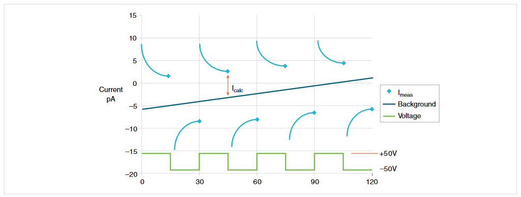
When this test is run, the V-Source will alternate between two voltages at timed intervals, named the electrification time. Current measurements are taken at the end of each of these alternations and after calculation of Icalc, the resistance values are computed. Icalc is a weighted average of the latest four current measurements, each at the end of a separate alternation. The resistance value is then converted to a resistivity value if the meter has been configured for resistivity measurements.
Figure 5 shows an example of the Alternating Polarity test using the test parameters shown and the resulting sample current from a typical high resistance sample. Note that the sample currents shown exhibit some capacitive delay, as many high resistance samples also tend to have significant capacitance.
Software
Keithley offers software to complete resistivity measurements on insulators using the alternating polarity technique. The KickStart high resistivity measurement application allows for reliable measurements of volume and surface resistivity of insulators according to ASTM D257 and IEC 62631-3-1 stanards. This app is designed for use with Keithley's 6517B Electrometer/HIgh Resistance Meter and the 8009 Resistivity test fixture. Use this application to:
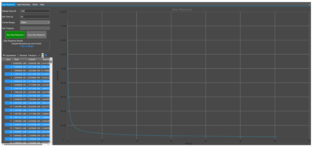
- Perform a step response in order to determine an electrification time appropriate to the materials time constant. See Figure 6.
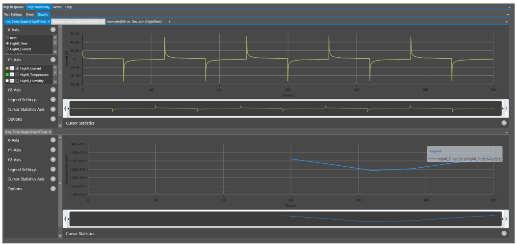
- Observe resistivity dependency on temperature and relative humidity using optional 6517-TP and 6517-RH probes.
- Use the alternating polarity technique to eliminate inherent background currents for the most accurate resistivity measurements. See Figure 7.
Test System Safety
Many electrical test systems or instruments are capable of measuring or sourcing hazardous voltage and power levels. It is also possible, under single fault conditions (e.g.,a programming error or an instrument failure), to output hazardous levels even when the system indicates no hazard is present.
These high voltage and power levels make it essential to protect operators from any of these hazards at all times.Protection methods include:
- Design test fixtures to prevent operator contact with any hazardous circuit.
- Make sure the device under test is fully enclosed to protect the operator from any flying debris.
- Double insulate all electrical connections that an operator could touch. Double insulation ensures the operator is still protected, even if one insulation layer fails.
- Use high reliability, fail-safe interlock switches to disconnect power sources when a test fixture cover is opened.
- Where possible, use automated handlers so operators do not require access to the inside of the test fixture or have a need to open guards.
- Provide proper training to all users of the system so they understand all potential hazards and know how to protect themselves from injury.
It is the responsibility of the test system designers,integrators, and installers to make sure operator and maintenance personnel protection is in place and effective
Keithley designed the 8009 Resistivity Test Fixture to accompany the 6517B to safely test volume and surface resistivity on bulk insulating materials up to 1000VDC.