
Oscilloscope Setup
There are two ways to set up modern oscilloscopes. One is using the Autoset button, which will automatically set up your oscilloscope at just the press of a button. However, it provides no understanding of how to optimize each setting on the scope. The other way is to use the Default Setup option on the front panel, which helps you begin setting up at a known starting point while clearing out any of the previous user’s settings so you’re effectively starting from scratch. This is the first step to setting up your oscilloscope. From this point, you can then adjust the Horizontal, Vertical and Trigger controls to meet your signal measurement requirements.
Fine Tuning Oscilloscope Horizontal Controls
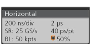
These controls used to be called sweep speed or sweep controls when the oscilloscopes were analog. However, today’s modern oscilloscopes are digitizing scopes, so these controls are now referred to as Horizontal Scale and are all about a trade-off between sample rate and memory. The sample rate is the speed at which the instrument takes snapshots of the incoming voltages. The faster we take the snapshots, the more of those need to be stored in memory and so the deeper the memory needs to be. So, for the best possible resolution, sample rate and memory need to be optimized.
Modern bench oscilloscopes generally give all the information you require on the screen. So, to set up the horizontal controls, all we need to do is find the ones we need in the horizontal menu on the oscilloscope. We can use those controls to set up sample rate and record length (time for which the record will remain in memory), or a relationship between them so that they are automatically optimized when you adjust the oscilloscope.
Setting Up Acquisition Controls
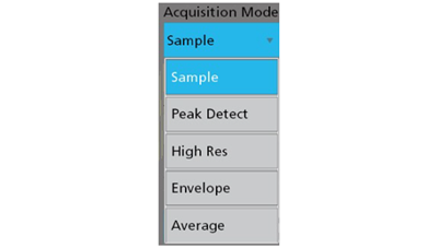
The acquisition settings govern how the samples are processed from the analog to digital converter into waveform from memory, especially when there are extra samples.
Sample Acquisition Mode
This is usually the default acquisition mode and it saves every nth sample. For example, if an oscilloscope samples at 25 gigasample per second but you only want to save 2.5 gigasample per second, the sample acquisition mode can be set up to save one point out of every ten.
Peak Detect Mode
This mode analyzes all the sample points and picks the highest one for each stored waveform sample. So, in the above example, rather than choosing one out of ten points at random, it picks the highest one from those ten.
Envelope Mode
This is similar to the Peak Detect mode except that it remembers the highest and lowest values for every waveform internal and displays both to give a range of what the voltage is going through.
High-resolution Mode
This mode takes all the n points that will contribute to one point and averages them, creating a single point as an average of all those points. This will slightly reduce the bandwidth of the oscilloscope but will also improve vertical resolution.
Average Acquisition Mode
This averages multiple acquisitions together, using a sample detection and then taking a mean of those points together over multiple acquisitions.
Optimizing Vertical Settings for Accurate Results
There are a lot of subtleties involved in vertical controls. The controls for position are quite straightforward as there’s usually a knob on the front panel and a value within the vertical menu for the channel that will help you set up the vertical position and the waveform on the screen.
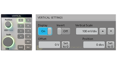
Offset, which changes the location of reference for that channel, is usually trickier than position because it’s not on the front panel but rather only found in a menu. The vertical reference point is, by default, set equal to the ground or zero volts, so as you adjust volts per division, they get adjusted with respect to that point. If you want a closer view of what’s going on with your signal, you might want to use a more sensitive volts per division setting, but this may cause the waveform to go above the screen because there aren’t enough divisions on the screen.
This is where the offset control can prove helpful, as changing the reference point allows you to position the waveform at the center of the ADC’s digitizing window and get a better vertical resolution to make more accurate measurements.
Optimizing the vertical offset and scale is all about getting the most out of the vertical resolution of the digitizer. This is best done by having your signal occupy at least 80% of the full-scale resolution to get the most out of the ADC. Most modern oscilloscopes allow you to optimize the vertical scale on a channel-by-channel basis as you add new channels. Another factor to consider is optimizing the bandwidth of the channel. Modern oscilloscopes are available with huge amounts of vertical bandwidth, but you might not need all of it.
Reducing the bandwidth helps eliminate noise and crosstalk so that you can see more subtle details of your waveform.
Oscilloscope Triggering Settings
Triggering is used to help you put signals and events of interest into memory. The oscilloscope is essentially always sampling data but the trigger looks for specific events to capture, display, and store into waveform memory. There are several different trigger controls, as follows.
Auto Trigger
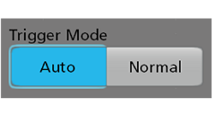
Contrary to the name, Auto Trigger does NOT automatically setup the trigger settings for you. Auto trigger is a visual aid that helps you get the oscilloscope set up properly. Initially, the oscilloscope waits for a trigger to be detected based on your settings. If that doesn’t happen within a certain timeframe, the scope initiates a trigger on its own. The auto-trigger setting keeps the display alive, showing what’s going on, even if the waveforms aren’t what you’re looking for. This can then help you make appropriate adjustments to your settings. Without this capability, the screen might be blank and you wouldn’t know if the circuit is working or there’s something wrong.
Normal Trigger
Normal trigger can be used when you only want the oscilloscope to acquire and display data when the trigger event happens. This is useful if you’re measuring signals for an infrequent event because then the auto-trigger would self-initiate triggers between your desired events. So, once the trigger is set up according to your needs, you can switch to normal trigger to acquire only the data you require.
Trigger Holdoff
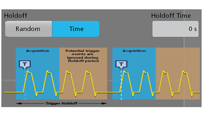
Trigger holdoff is helpful when you have an input coming in bursts of data. Usually, the oscilloscope processes the data captured at a trigger point and rearms the trigger circuit again to wait for the next event. This rearming can potentially happen in the middle of the next burst, causing the scope to trigger on an event within the next burst instead of at the beginning of the burst. The trigger holdoff specifies a period where the scope cannot rearm. So, when the oscilloscope is triggered and captures some data, it will wait until the holdoff period has expired before rearming the trigger circuit again.
Probing Considerations
Probing is one of the most critical things you must consider to get undistorted views of your signal. The prime concern here is to connect the signal you want to see to the oscilloscope accurately and without distortion. Here are some common considerations:
10x Probe Adjustment
Sometimes, your voltage measurements might be off by a factor of 10. There might be two reasons for this. One is that you’re using a 10x probe that cuts your signal amplitude by a factor of 10, but your oscilloscope isn’t set up to use one of these. The second is that the scope has been set up to use a 10x probe you’re not using one. Many modern oscilloscopes automatically detect the type of probe and set it up so that the readings are accurate, but if not, you can manually perform those channel settings.

Probe Compensation
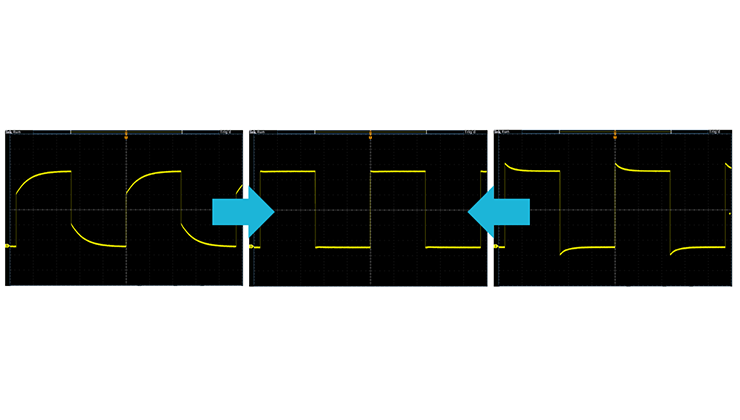
All 10x probes must be compensated whenever they’re connected to a new oscilloscope because if not, your high-frequency readings can be inaccurate with up to 20-30% amplitude errors. The probe compensation tool looks like a screwdriver and it comes with 10x probes.
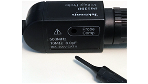
To manually compensate your oscilloscope probe, connect the probe to the probe compensation signal (typically mentioned on the probe itself, called probe comp or probe cal) and adjust the probe comp to get a good square wave on the screen, which indicates that the probe has been compensated properly. Some modern oscilloscopes can compensate probes automatically. All you need to do is connect the probe to the compensation signal, bring up the menu and click on the "compensate probe" button.
Ground Lead Length
If you’re not using a differential probe, the probe comes with a ground connection. The problem is that this ground lead can look like an inductor. The longer the ground lead, the higher the inductance. Combined with the probe tip’s inherent capacitance, this forms an LC tank circuit, which can cause ringing. Another issue is that a loop is being formed between the ground and the probe. The larger the loop area, the more noise is picked up. So, you need to be careful about ground lead length, especially when dealing with high-frequency signals. A shorter ground lead gives a much cleaner signal.

Conclusion
So, in a nutshell, knowing your oscilloscope’s interface, i.e., knowing how to read its vertical and horizontal settings, the acquisition system, and its trigger settings is the key to getting accurate results out of your oscilloscope. Apart from this, it’s always good to keep in mind all the probing considerations so that you get a clean, accurate output for your input.
Additional Oscilloscope Resources


