By Christopher Skach
Editor’s Note: This 5-part series of posts will walk you through the fundamentals of radar test and measurement. Here’s what we have on tap:
- Part 1: Radar basics, including continuous and pulsed radar, with a deeper dive into pulsed radar.
- Part 2: Lifecycle of radar measurement tasks, including key challenges in verification and production testing as well as a look at transmitter and receiver tests.
- Part 3: Analysis of radar signals including measurement methods and test setups.
- Part 4: Creating signals that look real to radar.
- Part 5: Tools for measuring modern radar systems.
The lifecycle of radar measurement tasks
The measurements needed for radar can vary considerably depending on the job to be done and the type or radar to be characterized. But whether you are working on radar system design and component selection or evaluating deployed radars, accurate and fast measurement capabilities are a must.
When performing radar design verification, you need to ensure the transmitted signal is correct, the receiver responds to and detects the correct signals, and that there are no spurious signals emitted from the transmitter. Unexpected outputs can range from unintended signals related to the desired pulse (such as harmonics, sub-harmonics and image mixing products), as well as spurious outputs unrelated to the desired pulse, such as radiation of internal local oscillators, coupling from digital clocks, spurious oscillations within RF circuitry, pulse errors, and so forth
cs> Might want to also mention interference from other close proximity signals in the band of interest such as wifi, cell towers etc. (environment)
In the modern world of software defined radar, modulated pulses, chirps, and other waveforms are usually not generated with traditional analog circuitry, but with digital signal processors (DSP) and direct digital synthesis (DDS) techniques. These digital techniques generate complicated signals directly at intermediate frequencies (IF) or RF frequencies. The signals only become analog when the synthesized digital data is passed through a digital-to-analog (D/A) converter.
Within the DSP, subtle software code and numeric errors such as poorly chosen filter constants, numeric rounding, or overflow errors can create very short-duration artifacts that may bear little or no relation to the desired output. A single DSP error can create momentarily incorrect RF output or glitches. Such issues can play havoc when filtered, amplified, and transmitted.
Spurious emissions can also interfere with other RF services in the deployment area and often provide a distinctive signature if they are specific to a particular transmitter design. Wideband radars can also “bleed” into surrounding spectrum causing unintended interference well outside the assigned spectrum.
Production testing
Production testing involves verifying that each manufactured product meets its specifications. Test tasks include tuning and calibrating assemblies, along with the compensation and calibration of analog modules, linearizers, and amplifier components. Results must be accurate and repeatable to assure the final product will function as intended. As component and subsystem vendors make changes to their processes, continued verification of performance is required without varying the tests throughout the product lifecycle.
Automated testing reduces the chance for operator error, which is a notable drawback of manual test processes and manually operated test equipment. With automation, test results can be reproduced regardless of production personnel changes. Also, training requirements can be significantly reduced.
Signal monitoring
Signal monitoring is a different challenge. For Signal Monitoring, there is less need to verify a specification, but more to identify signals that may be present in the surrounding area or show themselves only very rarely. These types of interfering signals can jam or reduce the effectiveness of a radar. When searching for pulsed or interfering signals, an RF analyzer must not “blink” when the signal appears. Discovering, triggering, and capturing infrequent signals or transient characteristics of signals are required before analysis can be performed.
Interference may be manifested not only as an infrequent problem but may be an issue of multiple signals contending for the same spectrum, either intentionally or unintentionally. Discovering such overlapping signals can be very difficult using traditional test equipment.
Basic RF Pulsed Radar Signals
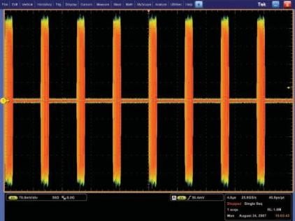
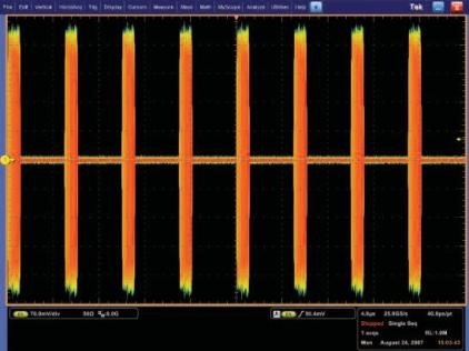
A simple pulse can be a single frequency that is turned on for a short time and then off again. The signal travels from the transmit antenna, reflects off a target and returns to the radar. The time it takes for the pulse to return represents the range, or distance to the target. An oscilloscope can show the time domain voltage waveform of the transmitted pulse. This includes all individual cycles of the RF pulse shown below.
A RF detector can be used to create a trace of the envelope of the pulse, instead of the individual cycles. This makes triggering much easier. A Vector Signal Analyzer (VSA), or a spectrum analyzer in zero-span, can display amplitude versus time. This is the equivalent of using a RF detector. The lower trace in the screen capture below is a spectrum analyzer detected envelope of a single RF pulse seen in the voltage waveform below.
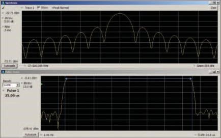
A spectrum analyzer can also show the frequency spectrum of the pulse. The sin(x) / x (pronounced "sine x over x") classic pulse spectrum plot is seen in the upper trace. A VSA can use a Fast Fourier Transform (FFT), or other Discrete-Time Frequency Transformation (DTFT), to make such a spectrum plot of a single pulse. A swept spectrum analyzer must either be in a "maximum trace hold" mode, or it must sweep slowly enough that at least one pulse appears at each position across the screen to provide a complete spectrum view. Without additional frequency processing software, the oscilloscope provides only the voltage waveform.
Transmitter tests
Modern radars often generate pulses at an IF where the processing is easier and then convert the IF frequency to the final CW frequency before amplifying it to the necessary high power. When testing an up-converter from the IF system, or testing the power amplifier, a radar pulse generator is needed in addition to the pulse analyzer.
There are several solutions available for generating radar pulses. Arbitrary Function Generators (AFGs), Arbitrary Waveform Generators (AWGs), and software to create the necessary pulses can generate baseband, IF, RF, or microwave signals using direct synthesis up to 10 GHz and higher. Test waveforms can be imported into the generators, synthesized, and replayed. Signal generation is often required in the selection and verification of analog transmitter components to test the margin of design and manufacturing processes.
Receiver tests
Testing the receiver portion of a radar system, when the companion transmitter is not yet available, requires pulse generation equipment. However, verification of receiver performance under varying signal conditions may not be possible using the companion transmitter. This requires a generator with the capability to add impairments and distortions to generated pulses. Common impairments are in-channel and out-of-channel signals and noise to test desensitization or blocking. This will verify the limits of receiver functionality. A generator of waveforms with arbitrary variation of any part of a digitally created waveform fills this need.
The next installment in this series will look at techniques for analyzing radar signals including measurement methods and test setups. In the meantime, be sure to check out our radar and electronic warfare application site.