

Energy storage device testing is not the same as battery testing. There are, in fact, several devices that are able to convert chemical energy into electrical energy and store that energy, making it available when required.
Capacitors are energy storage devices; they store electrical energy and deliver high specific power, being charged, and discharged in shorter time than batteries, yet with lower specific energy.
Supercapacitors are another type of energy storage device; they share certain characteristics with both capacitors and batteries, achieving higher specific energy than capacitors. Tektronix/Keithley first got involved with testing supercapacitors through our clients in the automotive market that were primarily looking for instruments to characterize supercapacitors in regenerative braking systems.
And then, of course, there are the rechargeable batteries — specifically the Li-ion batteries (LIBs) that started to dominate the market and became a broad new area of test and measurement.
Let’s take a short tour of battery testing.
Graphene and Advanced Cathode Materials Research
Graphene testing and nanotechnology techniques like using carbon nanotubes to control graphene and electrochemical properties caught the attention of our engineers and test specialists. Graphene oxides have been critical to the development of modern Lithium Ion batteries because they help stabilize and improve batteries’ chemical, thermal and electrical properties.
When Li-ion batteries were first being developed, the research involved testing graphite oxides and graphene with composite material. Keithley started to investigate how to characterize and ensure the best electrical conductivity performance at the most reasonable cost.
Keithley’s sensitive low-level measurement solutions and parameter analyzers such as the 4200A are widely used in testing and producing special materials like graphene, specifically in battery cell R&D departments.
Electrical measurements on conductivity were made with a Keithley 622x DC and AC current source and Keithley 2182A Nanovoltmeters connected to a four-probe fixture setup.
Cells Electrochemical Characterization
For a thorough electrochemical characterization, it is necessary to support charge and discharge testing on energy storage devices and batteries, in particular. The electrochemical performance characterization requires two specific measurements: cyclic voltammetry and galvanostatic / potentiostatic charge-discharge cycles.
For these specialized tests, Keithley released the 2450-EC, 2460-EC and 2461-EC Potentiostats, which are specialized versions of our Source Measure Units (SMUs).
SMUs can be programmed to apply a linearly variable electric potential for the electrolysis, while simultaneously scanning and recording the output current. All phenomena are strictly dependent on temperature, so we were typically combining these systems with special dataloggers like DAQ6510 that could track multiple environmental sensor responses in a time-aligned way.
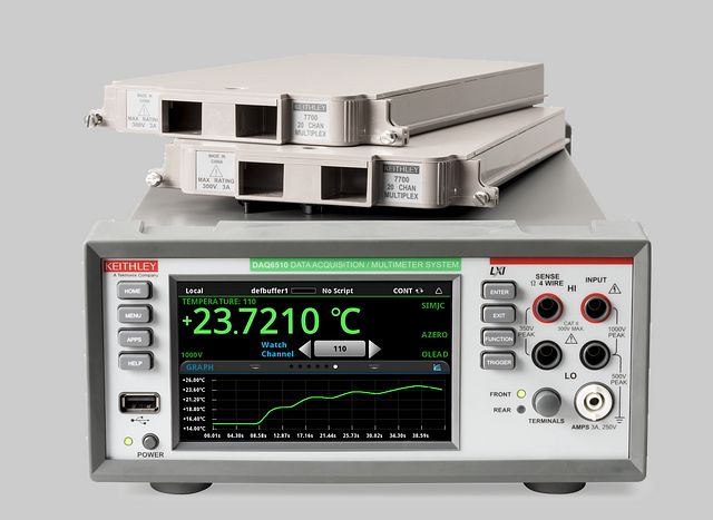
Figure 1: DAQ6510 is a precision data acquisition and logging system that creates a new level of simplicity compared with the often complicated configuration and control found in the industry
Li-Ion Batteries Manufacturing: a quick look into production
Li-Ion battery production is an extremely interesting market; LIBs are a popular choice for several applications that, for simplicity, we will group into three main categories:
- 1. The consumer market, which includes battery-operated IoT, medical wearables, smart home and general portable electronics
- 2. The transportation market, which is in large part the automotive EV battery testing market
- 3. The broad and complex stationary applications market, which includes uninterruptible power supply (UPS), data centers, renewable energy systems (RES), and batteries for grid-level storage.
Each of these main macro applications not only differ in energy and power density requirements, the battery form factor, discharge rate, efficiency, and safety, but must adapt in order to support ever-changing lifetime requirements. This translates to more complex specs, such as the number of charge/discharge cycles and other performance-related parameters.
Also, the needs of each from a test and measurement perspective differ significantly. Over the last several years, many national and international industry projects and consortiums have been created to work throughout the entire battery value stream, growing and sharing their expertise.
Multiple associations in Europe assembled players focused on battery production technology in different departments, from the machine and component supply, raw material provisioning and preparation, electrode production and the stages of assembly, from the cell level to module and pack production. All of these were propaedeutic steps in preparation to support the need for several battery plants in Europe—the so called “Gigafactories”.
These large facilities are supposed to produce battery systems for electric vehicles, which fall in the second of the three aforementioned markets: transportation/automotive.
Battery System Testing in Automotive
An automotive battery system is complex with a lot of electronics incorporated in a solid, protected housing. It contains a battery pack with relatively complex cooling and control systems, electrical and thermal sensors, and some communication wiring. The control unit acts as a “brain” and is called BMS or battery management system.
A battery pack is a system composed of several battery modules. Each battery module is composed of several individual battery cells.
If the chemistry is efficient at the cell level, you need to make sure that the optimization still exists at the module or system/pack level as well.
Different test sets are developed at the cell level, module level and system level. The same test Instrument may find space in different production stages and for different levels of batteries.
Let’s take a quick look at some of the value chain phases.
Cell-level Materials and Subcomponents, Electrode Manufacturing Testing
There is a lot of material (like complex polymers) processing in the early stages of the production of key components used in cell manufacturing. You need to make the separators, the case, the electrodes etc.
Tektronix and Keithley solutions relate to the electrical measurements taken on electrodes for instance. It is necessary to trace the impedance on electrodes to make sure the materials chosen for the anode and cathode do not massively contribute to the battery input impedance and stay in the range of a fraction of an ohm across a certain frequency range. Generally, customers design a specific fixture capable of accessing all interfaces between collectors and other layers; it is a necessary step for the accurate determination of electrical conductivity of different samples. A special chuck can be used to connect to it with the four-point probe technique.
Keithley state-of-the-art Nanovoltmeter 2182A combined with 622x Current AC and DC sources support such measurements. As said in the previous paragraph, these measurements are made mostly in the research stages and considered particularly useful when dealing with electrochemical noise measurements. The DC source applies a very precise constant current on the electrodes while the digital nanovoltmeter measures the correspondent drop in voltage.
Cell-level Assembly, Stacking, Tab Welding, Filling
Before filling the electrolyte into the cell, defective products need to be removed from production. To identify defective products, you can run a test on the insulator (also called the separator) that involves a charging-dwelling-discharging sequence and measure the leakage current.
When issues with the separator exist (membrane problems, decomposition etc.), the failure is easy to detect as the level of current is in the range of tens of mA. When insulation is good, the leakage current can be quite low (in the pico Ampere range). The insulation resistance test is also repeated in the module assembly and pack assembly stages to prove the insulation is good for different parts with respect to ground (chassis).
The Keithley model 6517B Electrometer/ High Resistance Meter offers insulation resistance measurements at various calibrated insulation test voltages. The 6517B has very low current sensitivity and a built-in 1kV voltage source with sweep capabilities. This simplifies performing leakage, breakdown, and high-resistance testing as well as surface resistivity measurement on insulating materials.
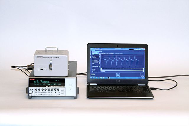
Figure 2: Keithley electrometer can embed a high voltage source for testing insulation
Cell level Formation- Aging – End of Line (EOL) testing
The formation and electrical testing of individual battery cells occurs in the last steps of the production line and generally represent a significant bottleneck for mass production.
One of the key characteristics of a battery cell is its performance over the course of its life, so cells are put through an aging process to investigate cell degradation.
A typical characterization of performance over time is achieved by cycling the cells. Cycling is essentially a repeated charging and discharging process.
A current and voltage profile representative of the intended application under typical application-related stress conditions (e.g. temperature variation) is applied to cells.
It is important to note that lifetime requirements for cells, modules, and systems are determined by the application where they will be used (e.g. electrified mobility, Consumer Electronics, etc.).
There are several cycling (charging-discharging) protocols defined by standards for each specific application (e.g. IEC 62660-2).
Depending on the methodology, a programmable power supply source is used to apply a constant current - constant voltage (CC-CV) charge procedure, taking the cell from an initial set voltage to a final set voltage. Then the voltage is fixed, and the current is reduced until a certain capacity is reached.
A discharge cycle is generally applied via a programmable electronic load.
All these cycles are repeated several times with some variable “relaxation” time between charge and discharge.
These tests are typically executed in a temperature chamber; the variation in temperature that a cell experiences is also dependent on the intrinsic thermal variation during charging and discharging.
A multi-channel system based on several source measure units like Keithley SMUs, which capable of measuring while sourcing or sinking, can be used in this stage. The system typically requires multichannel DMMs with specific resolution, accuracy, and stability over time and across environmental conditions.
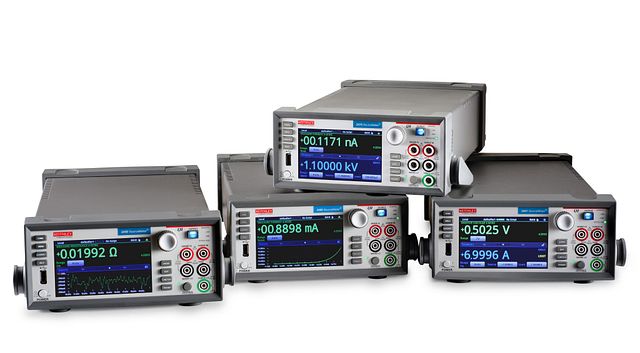
Figure 3: Keithley Source and Measure units can cycle battery cells with high precision, accuracy and stability
Players compete in introducing the most efficient methodology on end-of-line testing and formation. Meanwhile system integrators challenge themselves in developing efficient test procedures and parameter extraction regarding cell quality monitoring.
Test racks in this space are generally highly automated, involve multiple instrument units, and generally perform the following measurements:
- - Internal resistance measurements (DC)
- - Open circuit voltage (OCV)
- - Leakage current
- - Charge/discharge pulsing
The automation of data collection is critical here and helps the following grading phase, when cells are sorted according to their performance test results.
Internal Resistance and OCV Measurements
The performance of a battery and its efficiency during the charge and discharge process can be evaluated in a few different ways, and there are several indicators to look for. The battery internal resistance characterization is one of them. It basically means accurately characterizing the battery’s changes under several charge/discharge current rates, state of charge (SoC), temperature and other aging indicators.
OCV is the voltage measured at the terminals of the battery after enough rest time (sometimes called relaxation), and it is a key measurement for Li-Ion battery cells.
OCV also varies mostly according to battery SoC and, to a lesser extent, according to the temperature. These details can be used to create a battery equivalent model, which is used to design a battery management system (BMS), in addition to assessing the battery specs and condition.
The internal resistance in the battery accounts for the voltage drop across battery’s terminals when a load is connected compared to no-load voltage and can be derived from OCV measurements.
OCV is generally not just a measurement, but a set of measurements. In fact, we call it the OCV characterization of the battery, and we trace an exhaustive analysis derived from a curve on an SoC versus OCV plane.
To trace this curve, you need to bring the battery to specific states of charge. This is typically performed by charging or discharging current in a pulsed way using a smart source/load then waiting for some amount of rest time, and then measuring the open-circuit potential at the electrodes.
A Keithley SMU like the 2461 is the perfect instrument to perform this test. In fact, it can either source or sink the cell current in a controlled way while measuring the cell current and voltage with a four-wire (Kelvin) connection with contact check. All of this is easily automated and controlled by a programmed embedded microprocessor. This specific SMU offers controlled pulsing capabilities for both charging and discharging.
The accuracy of the voltage measurement in OCV is a discriminating factor for the choice of the instrument. In some cases, the typical 6 ½-digit measurement resolution, the thermal stability, and most importantly, the accuracy of an SMU can be considered insufficient.
For this reason, some test setups involve a special digital multimeter, the Keithley DMM7510, that is a standard in Li-Ion battery cell testing. Its low-noise, 32-bit A-D converter allows 7 ½-digit resolution and metrology grade accuracy.
Busbar Weld Impedance Safety Test Workstation in Battery Packs Manufacturing
A battery module is composed of multiple cells that are connected in parallel or series to achieve the desired voltage output. All cells are laser-welded to a busbar—a long conductor that is isolated from the ground and is responsible for carrying high current for the distribution of power from the battery. The VSH-Busbar weld impedance test characterizes the impedance of the weld. Small resistances in the weld can generate enough heat to degrade the batteries and lead to early failures or unsafe operating conditions. By measuring the resistance before testing the battery operation, defective modules can be quickly removed from the line.
Measuring the impedance of the weld involves sourcing a current across the weld and measuring the voltage to calculate the resistance. Test execution speed and measurement accuracy are the two most important considerations when measuring the weld impedance. This can be done using SMUs like the Keithley models 2460 or 2461 and either the model 3706A System Switch and Multimeter or the model DAQ6510 Data Acquisition and Logging Multimeter System.
The 2460 and 2461 SMUs are capable of sourcing up to 7A for battery systems that require high current. The impedance of the weld can be as small as a few milliohms, so it’s important to use a sensitive enough meter to measure very small voltages. The model 3706A features a 7.5-digit digital multimeter (DMM) and can measure 10s of nanovolts on the 100mV range. Since a battery pack could have close to 80 welds on one busbar, Keithley instruments support mainframes with configurable slots for multi-channel plug-in modules, eliminating the need for rewiring. The process of closing each channel to measure it is obviously automated for speed and efficiency.
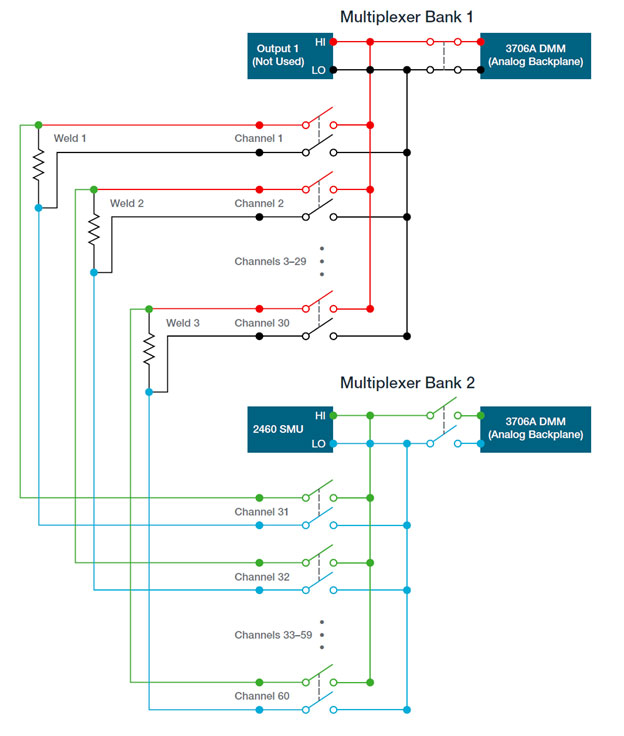
Figure 4: A schematic example of an automated system for impedance test in battery production
ATE Design in Battery EOL Testing
When the battery-operated device is a vehicle, things become quite interesting.
First, you tend to deal with a significantly large number of cells to test, and the test equipment is sophisticated and requires very high reliability. ATE design in this application space needs to support multiple tests on multiple devices. The characterization methodologies also need to be simple and a low-cost alternative to the more advanced and higher-resolution scientific alternatives, which tend to be time-consuming and expensive to set up.
At the cell level, there may be “electrochemical workstations” to set up. But when dealing with modules, the focus is on higher current testing. Finally, the test on complete systems (packs) can involve high currents and high voltages (1000A and 1000V or more are quite common today).
Single cell testers are typically multi-channel systems. What matters here is the voltage and current resolution of the measurement and its stability under varying environmental conditions.
BMS ATEs are designed to accurately monitor cell voltages and temperature, and monitoring the changes in impedance is key.
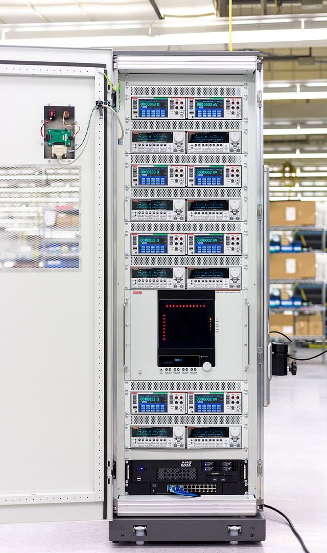
Figure 5: Typical test rack with multichannel high accuracy DMMs and related switching unit
Impedance Measurement of Cells
The battery impedance of cells is a key measurement taken during the formation and aging stages. All batteries experience a reduction in performance with cycling. This can be due to the degradation of one or more components or interfaces. There are different methodologies that can be applied, from electrochemical impedance spectroscopy (EIS) to direct diagnostic measurements.
EIS is a non-destructive technique that provides a considerable amount of information in a relatively short time span while preserving the integrity of the battery. To conduct this test, a small AC signal is applied over a wide frequency range and the response is measured. Measurement methodologies involving a span on frequencies are applied to individual cells, but they aren’t applicable for larger sizes and larger operating power modules. In the automotive battery management system (BMS) space, the test is carried out on multi-cell batteries of varying capacities and mismatched cells have to be carefully tracked. Cell mismatch can occur due to battery overcharge, discharge shorts, or simply because of aging.
The Consumer Portable Battery-Operated Electronics: testing needs
What about the testing needs in the market of IoT, medical wearables, and smart home devices?
Embedded devices used for IoT applications are strictly connected to the battery choice, since this impacts the expected lifetime of the device. Batteries needs to be sized to support device workloads for a long period of time. The battery market for IoT relates to small (also “micro”) batteries with thin, flexible, and sometimes unconventional form factor.
When choosing the right battery for their specific application, designers have to consider multiple parameters, including:
- Battery type and declared specs
- Operating temperature range and storage conditions
- Potential energy losses and circuitry leakage
- Application requested ranges and power consumption profile
Let’s focus on the last bullet for a second. Designers need to be aware of the power consumption profile and precisely control the schedule of each executed task by any of the device units (processors, transmitters, etc.). IoT device workloads are sequences of tasks periodically launched in execution with short-duty cycles.
The rate of discharge is strictly dependent on this power schedule, and the intensity, duration, and frequency of these “power usage” pulses. Also, it’s important to control the voltage range of the application, and be aware of the maximum, nominal, and cut off voltage for each subcomponent to correctly operate it.
Based on all the aforementioned considerations, an embedded designer needs to perform:
- A dynamic model battery simulation
- A dynamic current charge / discharge testing (with pulsing sink capability)
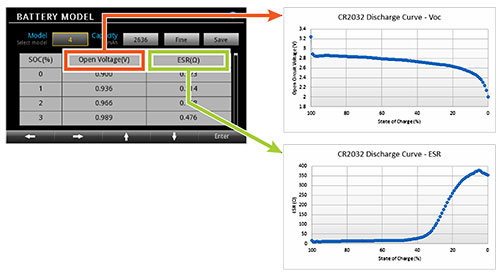
Figure 6 : Battery Simulators need to support modeling like profiles of open circuit voltage and internal resistance as a function of the battery's state of charge
The typical test bench will include:
- A basic oscilloscope operating at max 500MHz (typically lower) like the Tektronix TBS2000B or MDO 3 series
- A multi-channel DC power supply with battery simulation capability (generally linear) like the Keithley 2230 model
- An electronic load, possibly programmable, like that offered by Keithley SMUs
- A DMM with sufficient resolution (DMM6500 when 6 ½ digits is sufficient or for low-power consumption applications, the DMM7510 is recommended to step up to 7 ½ digits)
- An instrument data control software environment (typically PC-based) like Kickstart.
Voltages in this application space do not exceed 10V - 15V max, but current sink in some power-hungry conditions can reach a few Amps (3-4A).
Keithley battery simulators span from the solid 2306 series for production to the 2281S bench solution.


