Introduction
The oscilloscope provides a window into the world of electrical signals. Early oscilloscopes could display only repetitive or continuous electrical events, which limited their application.Then in 1947 Howard Vollum and his newlyformed company, Tektronix, announced the first commercially available triggered-sweep oscilloscope.
That first triggered-sweep instrument with its calibrated graticule display transformed the oscilloscope from a qualitative tool for viewing the general features of electrical impulses into a quantitative measurement device - one that revolutionized the electronics industry. For the first time, engineers could capture transient events and make accurate voltage and timing measurements on signals of all kinds. Ever since its earliest oscilloscope models, Tektronix triggering innovations have led the market.
The trigger event defines the point in time at which a repeating "window" of waveform information is stabilized for viewing.Imagine you are taking a trip in your car. You need to arrive at your destination in the minimum amount of time, but you want to photograph a particular landmark along the way. You know you can get to your destination quickly because you have a very fast car, but what’s your strategy for capturing the point of interest on film? One choice would be to randomly snap pictures on your camera as you drive and hope to capture an image of the landmark. Obviously this leaves too much to chance.
A more logical approach would be to give the driver instructions on where to stop so you can get a good clean picture of your point of interest. Waveform data in many oscilloscope applications is like all that the scenery you don’t care about. In a high speed debug application, your circuit may be working 99.999% of the time or (commonly) even more. It is the .001% of the time that is causing your system to crash or is the portion of the waveform you need to analyze in more detail. Your oscilloscope may have the banner specifications (bandwidth, sample rate, record length) to make the trip quickly, but if you cannot capture the data of interest it will be a limited debug and analysis tool.
Tektronix Pinpoint® trigger system in the DPO7000 and MSO/DPO/DSA70000 oscilloscope series is the most comprehensive high performance trigger system in the industry. Of course, the Pinpoint trigger system encompasses the usual range of threshold and timing related triggers.Equally important, it also features Dual A- and B-Event Triggering, Logic Qualification, Window Triggering, and Reset Triggering. It all adds up to almost unlimited flexibility in defining the trigger event.
Pinpoint triggering is implemented using Silicon Germanium (SiGe) semiconductor technology, which makes all the trigger features useful even at frequencies approaching the full analog bandwidth of the oscilloscope. The features and performance of Pinpoint triggering allow you to 'pinpoint' the most elusive events of interest in your high speed digital designs.The Advanced Search and Mark feature of the DPO7000 and MSO/DPO/DSA70000 Series finds unique events in waveforms. It scans acquired waveform data for multiple occurrences of an event and marks each occurrence. Search and Mark features have a close relationship with the Pinpoint trigger system since they both can be used to discriminate signal characteristics. Search and Mark includes signal-shape discrimination features of the Pinpoint trigger system and extends them across live channels, stored data and math waveforms.
This document discusses the fundamentals of triggering and how Pinpoint triggering and Search and Mark takes triggering in real-time oscilloscopes to new levels of productivity.
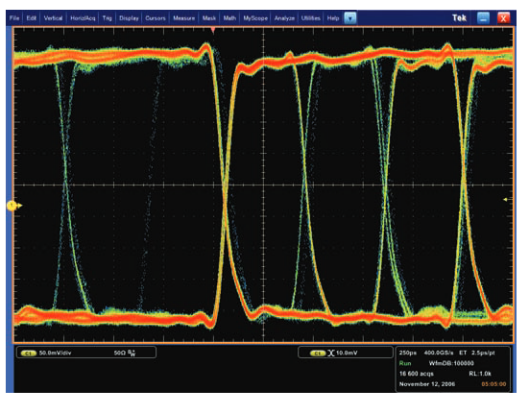
An oscilloscope's trigger function synchronizes the horizontal sweep at the correct point in the signal, essential for clear signal characterization. Trigger controls allow you to stabilize repetitive waveforms and capture single-shot waveforms.The trigger makes repetitive waveforms appear static on the oscilloscope display by repeatedly displaying the same portion of the input signal. Imagine the jumble on the screen that would result if each sweep started at a different place on the signal! This effect is illustrated in Figure 1. Prior to the triggered sweep oscilloscope, this is what the display users had to visually inspect a waveform.

Edge Triggering
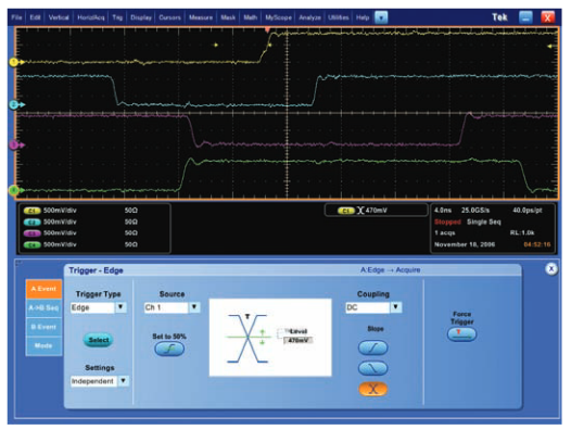
Edge Triggering, available on all modern oscilloscopes, is the original and most basic and common type of triggering.Edge triggering is usually adequate to give you a look at the essential amplitude and timing characteristics of the waveform. Figure 2 depicts a setup window for Edge triggering in the Pinpoint trigger system.
Trigger Source
It is almost always necessary to trigger the oscilloscope, but not necessarily on the signal being displayed. Among the sources commonly used to trigger the sweep are:
- The incoming signal on any input channel
- An external source other than the signal applied to an input channel
- The "line" power source signal
- A signal internally calculated by the oscilloscope based on its evaluation of one or more inputs
Most of the time, you will leave the oscilloscope set to trigger on the channel displayed. But the instrument can trigger on the input from any channel whether or not it is displayed, or from a source connected to a dedicated trigger input. Most Tektronix oscilloscopes also provide a discrete output that delivers the trigger signal to another instrument a counter, signal source, or the like.
Independent Trigger Level Settings
Many electronic devices incorporate a variety of logic families with differing input voltage requirements. This in turn requires a separate trigger threshold voltage setting for each logic family. In the past, oscilloscopes shared trigger level settings across all source channels. Each time a different channel was selected as the trigger source, the threshold had to be changed. The Pinpoint trigger system provides a choice: unique trigger level settings for each input source, or a global setting that applies across all channels.
Trigger Level and Slope
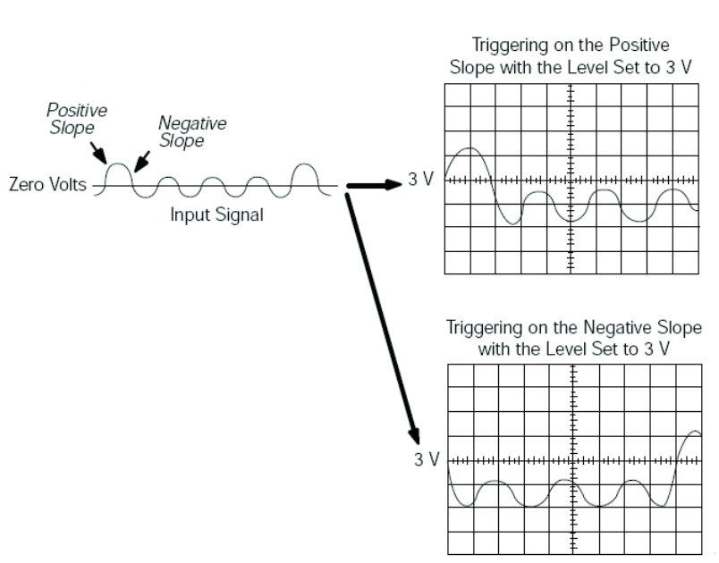
The trigger level and slope controls provide the basic trigger point definition and determine how a waveform is displayed, as illustrated in Figure 3. For edge triggering, you select the slope (positive or negative) and level, and the oscilloscope triggers when your signal meets these conditions. This is known as the threshold crossing. The Trigger Level is indicated by a small arrow on the right hand side of the display (Figures 4a-4c). The color of the arrow corresponds to that of the selected trigger source channel. It is common practice to set the trigger level at 50% of the peak-to-peak voltage excursion but this is by no means a requirement.
Trigger Position
The Horizontal Position knob located on the oscilloscope's front panel is used to position where the trigger event is displayed on screen. Varying the horizontal position allows you to capture what a signal did before a trigger event, known as pre-trigger viewing. Thus, it determines the length of viewable signal both preceding and following a trigger point.
Digital oscilloscopes can provide pre-trigger viewing because they constantly process the input signal, whether or not a trigger has been received. A steady stream of data flows into the oscilloscope’s memory; the trigger merely tells the oscilloscope to save the data in the memory at the instant the trigger occurs. Pre-trigger viewing is a valuable troubleshooting aid. If a problem occurs intermittently, you can trigger on the problem and scroll through the record to analyze the events that led up to it. Often the cause of the problem can be found in that information preceding the trigger.
In Figure 4, the trigger position is set to the fourth major horizontal graticule mark, equivalent to 40% of the horizontal sweep. The trigger point can be positioned anywhere from 0% to 100% of the record. At 100% position, the entire record occurs before the trigger point, allowing maximum trigger preview. At 0%, the entire record occurs after the trigger allowing maximum post-trigger viewing. If you need to go beyond one full record after the trigger event, then a delayed trigger can be used. Delayed triggering will be discussed later.
Triggering On Both Edges
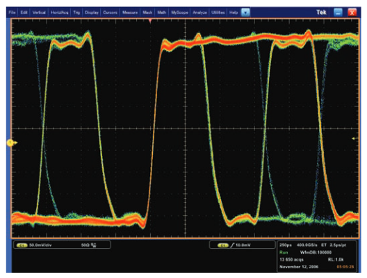
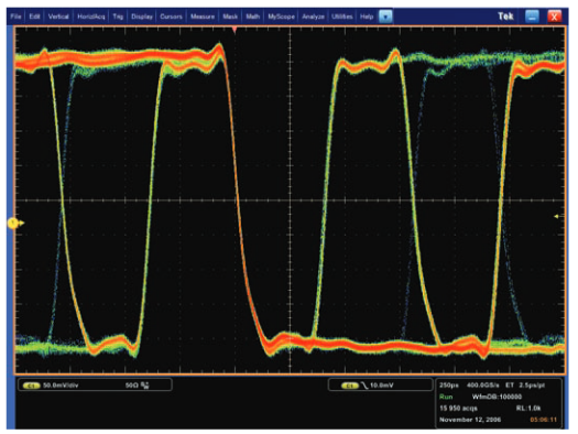
Positive and Negative slope settings (Figure 4a and 4b) have been offered in trigger systems for years. The Pinpoint trigger system also allows you to trigger on both Positive and Negative slopes (Figure 4c) which is often useful when looking at jitter on high speed clock and data signals. Figure 4a, 4b, and 4c show the result of changing the trigger slope from Rising Edge, to Falling Edge, to Both Edges, respectively.
Advanced Trigger Types and Controls
As waveforms, particularly the digital signals in both parallel and serial buses, have gotten more complex, the venerable edge trigger has become too limited to suffice as the sole means of acquisition. Continuing the photography analogy mentioned earlier, edge triggering simply doesn’t give the oscilloscope enough information about "where to stop" for the best pictures.
Advanced triggers respond to more rigorously specified conditions in the incoming signal, making it easy to detect, for example, a pulse that is narrower than it should be. Such a condition would be impossible to detect with an edge trigger alone. Advanced trigger controls enable you to isolate specific events of interest.
The Pinpoint trigger system gives you highly selectable control over the type event you are trying to capture. You can trigger on pulses defined by amplitude (such as runt or window);qualified by time (pulse width, glitch, slew rate, setup-andhold, and time-out); both amplitude and time using window triggering; or delineated by logic state or pattern (logic triggering).
The intuitive user interface allows rapid setup of trigger parameters with wide flexibility in the test setup to maximize your productivity. The advanced trigger menu can be displayed by selecting the trigger setup menu item with a mouse or the oscilloscope’s touch screen or by pressing the ADVANCED button in the TRIGGER section of the front panel.Many oscilloscopes offer dual A-B triggering. The A (main) trigger is usually a full-featured system that incorporates advanced triggers, while the secondary B trigger is limited to edge-style detection. The A trigger acts as a qualifier. Its occurrence enables the B trigger to look for a defined voltage threshold.
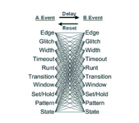
Tektronix DPO7000 and MSO/DPO/DSA70000 Series oscilloscopes with Pinpoint triggering are different. They have two complementary trigger circuits allowing full advanced trigger qualification on both the A- and the B-Events. This is referred to as Dual A- and B-Event triggering.
Pinpoint triggering offers Dual A- and B-Event triggering with the following trigger types: Edge, Glitch, Width, Runt, Timeout, Transition Time, Setup and Hold, Pattern, State, and Window.
Glitch Triggering
Glitch triggering accepts (or rejects) only events whose pulse width falls below a defined limit. A polarity of Negative, Positive, or Either can be selected. This trigger control enables you to examine the causes of glitches (no matter how infrequent) and their effects on other signals. The Pinpoint trigger system’s user interface allows you to search for glitches less than a minimum value of 300 ps and detect glitches down to 150 ps wide with a minimum rearm1 time of 300 ps. In Figure 5a, Glitch triggering is used to trace a crosstalk problem. Channel 1 triggers on the glitch that is causing logic uncertainty in the system, while channel 3 identifies the "offender" signal from an adjacent data line.

Width Triggering
Width triggering allows you to accept (or reject) only those triggers defined by pulse widths that are between two defined time limits. This is useful for observing Inter-symbol Interference (ISI), which can occur when the bit state changes after a long sequence of bits having the opposite state; for example, when a "1" occurs after a series of "0" states. In 8b/10b encoding bit times can range from one to five bits, while PRBS signals may have widths that vary even more.
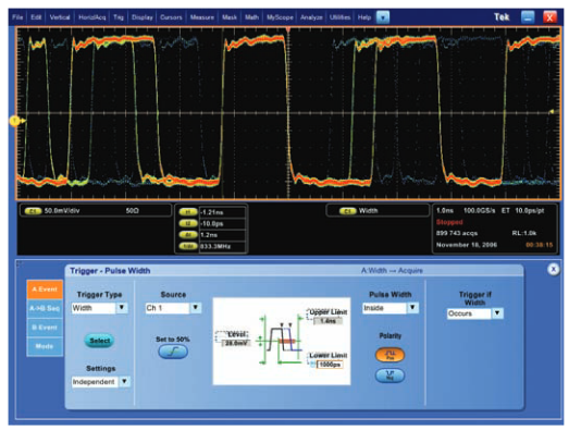
With width triggering a pulse polarity of Positive or Negative can be selected. Pulse Widths can range from 150 ps to 1 s with user interface control down to 300 ps and a rearm time of 300 ps. In Figure 5b, Width triggering is used to trigger only on positive pulses that are four bits long in a fast serial bit stream.
Runt Triggering
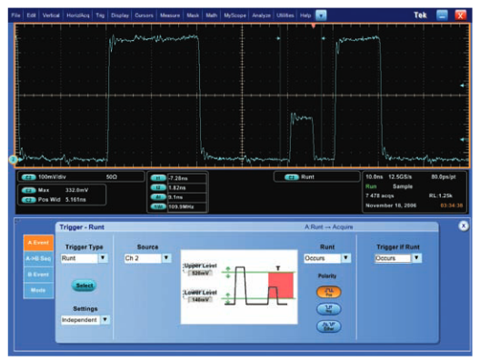
Runt pulses in digital signals often represent meta-stable conditions that can throw a digital system into an unknown state. Runt triggering allows you to accept only those triggers defined by pulses that enter and exit between two defined amplitude thresholds. A runt can also be time qualified with a minimum pulse width of 200 ps and a rearm time of 300 ps. A runt polarity of Positive, Negative, or Either can be selected.In Figure 5c, the runt trigger levels are set up at the minimum threshold values of a particular logic family. The pulse that falls below the specification is captured.
Timeout Triggering
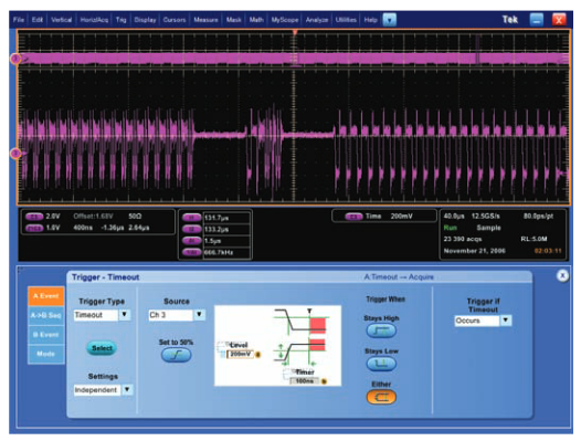
"Dead times" in clock or data signaling are sometimes designed into a system. However, if not properly timed with other system events, dead time can cause system communications errors. It is often useful to trigger on these dead times to discover whether they exist, and then to investigate their timing with other signals. Using Timeout trigger, you can trigger on an event which remains high, low or either, for a specified time period. The period can be adjusted from 300 ps to 1 s using the timer control. In Figure 5d, timeout triggering identifies a dead time in a bi-directional bus data stream. The timer is set to 100 nsec, guaranteed to be larger than any data width in the signal. The dead time is approximately 340 ns. The acquisition counter identified 45 timeout events in 10 seconds, indicating that this event occurs only .0000015% of the time in the repeating bit stream.
Transition Time Triggering

Edges (transition times) that are faster than necessary for their operational environment can radiate troublesome energy. Transition times that are too slow (on a clock for example) can cause circuit instability. Transition Time triggering allows you to trigger if the time interval from the low-to-high and/or high-to-low thresholds is slower (larger) than, or faster (smaller) than a specified time, with Positive, Negative, or Either polarity selected. In Figure 5e, transition time triggering is used to identify a clock edge that is slower than 3.5 nsec.
Setup-and-Hold Triggering
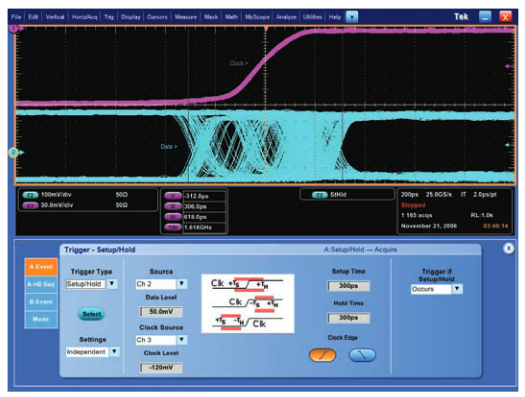
Setup-and-Hold violations can cause data errors that can ripple through an entire system. Setup-and-Hold triggering makes it easy to capture specific signal quality and timing details when a synchronous data signal fails to meet setupand-hold specifications. It allows you to trigger if a positive or negative data edge (transition) occurs within the defined setup and hold time windows of the positive (or negative) clock edge. Only setup-and-hold triggering lets you deterministically trap individual violations that would almost certainly be missed by using other trigger types. Figure 5f shows 1165 acquisitions captured with a setup time of less than 300 ps and a hold time of less than 300 ps.
Window Triggering
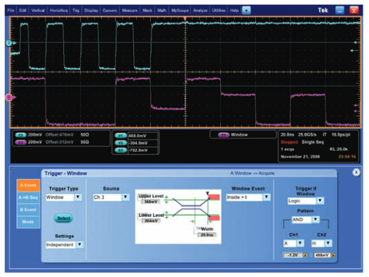
In many high speed designs, several internal component buses share the same bus on a circuit board. An array of buffers controlled by either hardware or software is used to multiplex the correct data onto the main bus. The multiplexer logic is supposed to enable only one element to use the bus at any one time. Design errors can cause bus contentions in which a bus, meant to have two logic levels, experiences a “middle” state where the signal is neither a ‘1’ or a ‘0’. Window triggering can easily capture bus contentions. With window triggering, the oscilloscope triggers on an event that enters (or exits) a window defined by two user-adjustable thresholds. Additionally, a time qualifier on the Window trigger can also be used to complete a rectangular time window that triggers the oscilloscope if a signal either enters or exits. The minimum window width is 300 ps with a minimum rearm time of 500 ps. Figure 5g illustrates a captured bus contention event. The trigger levels are set to the Hi and Lo threshold voltages of the applicable logic family
Logic Qualification

With Pinpoint triggering, all the advanced trigger types described above (Glitch, Width, Runt, Timeout, Transition Time, Setup-and-Hold, and Window) can also be optionally logic qualified, another powerful tool for isolating events. Figure 6 shows Logic Qualification being used to capture a setupand-hold where channels 1 (yellow) and 2 (blue) are Data and Clock, respectively. The trigger event is logic qualified by channel 3 (magenta) and channel 4 (green) both being high. Triggers only occur on setup-and-hold violations when the logic condition is satisfied. In digital circuits it is often desirable to define trigger conditions based on the logic states of the signals you are observing. A four-channel oscilloscope can use the logic state of up to four inputs to trigger the scope.
In the Pinpoint triggering system there are two types of logic triggering:
- Logic Pattern Triggering
- Logic State Triggering
Logic Pattern Triggering
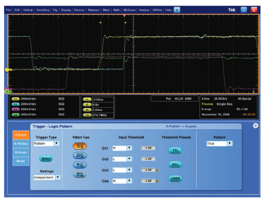
Logic triggering (Figure 7a) allows you to trigger on any logical combination of available input channels— especially useful in verifying the operation of digital logic. The oscilloscope triggers when a logical pattern (AND, OR, NAND, NOR) is satisfied by the input channels. Traditional logic families (TTL and ECL) provide pre-defined threshold levels, or USER can be used to set thresholds for logic families such as high speed CMOS. On the MSO70000 Series, a logic pattern up to 20 bits wide can be defined as a trigger condition. This is ideal for isolating the particular system state in complex designs like memory buses where timing verification is critical.
Logic State Triggering
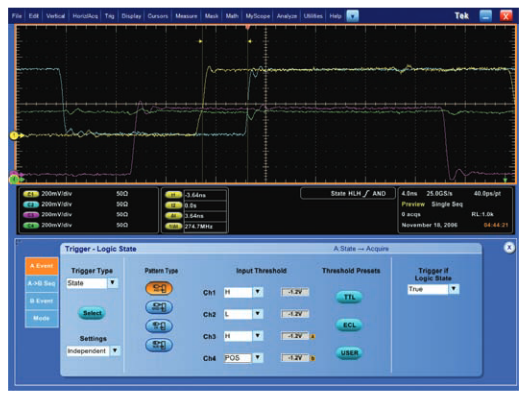
Similar to Logic Pattern triggering, with Logic State Triggering, the trigger is defined by any logical pattern of channels 1, 2, and 3 (and channels D0-D15 on the MSO70000) clocked by an edge on channel 4 (and Clk/Qual on MSO70000), as shown in Figure 7b. The trigger can be on either the rising or falling clock edge. This type of trigger is very useful when debugging propagation delay and metastability issues in circuits containing flip-flops and shift registers. Logic State Triggering can be useful when troubleshooting parallel buses in which there is a discrete clock line and many data signals, while serial triggering (discussed later) is useful for triggering on embedded clock data in serial buses.
The Primary Trigger Event
The A-Event
Thus far we’ve discussed ten different trigger types used to tell the oscilloscope the set of conditions for capturing and displaying the waveform. Most modern highperformance oscilloscopes permit two trigger definitions; in Tektronix instruments these are known as the “A” and “B” events with the former being regarded as the primary trigger event. For many applications, there is only one event of interest and A-Event triggering alone is sufficient.
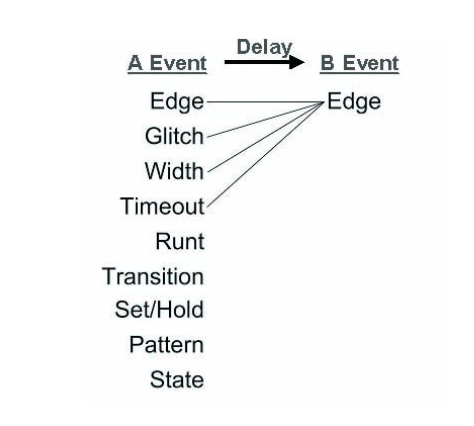
Delay Triggering
If the event of interest is more than one full waveform record length past the A-Event, delay must be used to display the event on screen. Delay from the A-Event can be specified in time (ranging from 3.2 ns to 3 Ms) or number of events (ranging from 1 to 2 billion events).
AB Sequence Triggering
In the most demanding applications a single trigger event is not sufficient to fully define the circuit behavior that creates the event of interest. Going back to the trip we’re taking in a car, imagine when you pull over to take your picture, you notice yet a more interesting detail, a lone eagle sitting on a perch. You use the features of your camera (zoom, shutter speed, etc.) to capture this even more interesting event. In high speed logic circuits it is often desirable to trigger based on a sequence of events. A second event or B-Event can be defined.
The B-Trigger circuit can be set up to start looking for an event after a specified amount of time (known as Delay by Time), or number of events (known as Delay by Events). Once the time or number of events is satisfied, the B-Event circuit waits to capture the next event that comes along. In other trigger systems, the B-Event trigger was limited to Edge qualification. That is, the only condition for the B event was a threshold crossing after the A event conditions had been met.
As discussed earlier, Pinpoint triggering has a far more versatile dual trigger system that offers a broad set of trigger types for the B-Event. The A- and B-Event trigger menus are similar, as is the range of conditions that can be stipulated for either trigger.
Reset Triggering
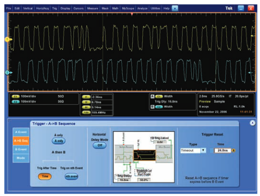
A B sequences can be used to "navigate" through a series of pulse events in a complex system. For example, a start-offrame pulse can serve as the A-Event and clock pulses might be used for the B-Event. By selecting the nth B-Event you can view system activity n-clock cycles after the start-of- frame. Delay by Time triggering is often used to ignore activity until a specified time has passed after a sync pulse.
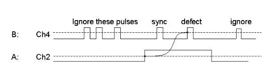
The timing diagram in Figure 8 shows a common application in the disk drive industry, though it is not limited to that field. It also applies to other digital debug applications where you want the trigger system to ignore portions of the waveform. In this example, the need is to identify data defects only when the read gate signal of the drive is high. In this case channel 2 is connected to the read gate signal and channel 4 is observing the data being read. Thus, what is needed is a trigger that ignores the data signal when channel 2 is low and triggers on channel 4 if there are too many pulses in the data. Previous trigger systems do not allow you to “stop looking” for a B-Event, they simply will trigger on the next B-Event that comes along or wait indefinitely for it. Pinpoint triggering adds this Trigger Reset feature to the A B Sequence system, directing the instrument to stop waiting for a B-Event when a certain reset criterion is met.
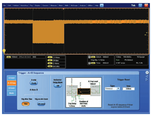
Reset triggering adds three new selections to the Sequence setup: Reset A Trigger after a specified amount of time (Reset By Timeout), Reset A Trigger after a specified rising/falling transition (Reset By Transition), and Reset A Trigger when a logic state is met (Reset By State).

Figure 9 uses Reset By State to trigger on the third pulse (defect) after the sync pulse on the data signal (channel 4 – green trace). The A-Event is an Edge trigger on the Gate signal (channel 2 – blue trace). A B Sequence By Events is used to trigger on the defect pulse. The trigger sequence is reset when the Gate signal satisfies the logic condition of returning to a low state. The trigger sequence as a whole ensures that the oscilloscope will only trigger when a defect is detected.
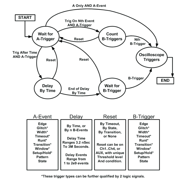
Sequential Logic Triggering
As discussed above, the paired features of Dual A- and B-Event Triggering and Reset Triggering allow the oscilloscope user to set up a sequence of events to trigger on (or not). The state machine that represents the Sequential Logic trigger event is shown in Figure 10.
Multiplying Your Triggering Choices
Pinpoint triggering architecture sets a new benchmark in oscilloscope efficiency and effectiveness. The addition of Reset Triggering and Dual A- and B-Event Triggering increases the range of standard triggering selections from a maximum of about seventeen combinations, when only Edge is the B-Event Trigger, to more than 1400, as shown in Figures 11a and 11b respectively. With all these choices available, you can define suspected error conditions with much greater precision, speeding your progress toward the root cause.
Application-Specific Triggering
The A-Event menu in the Pinpoint trigger system has more trigger types designed to simplify your work with the complex signal formats used in computing platforms, communications, networking, video, and more.
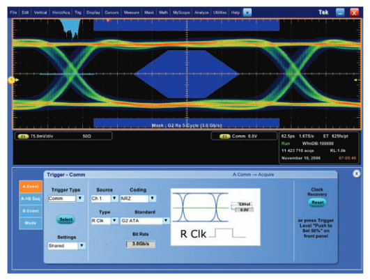
Communication Triggering
The Comm (Communication) Trigger appears in the A-Event menu in the Pinpoint trigger system. Mask testing involves triggering the waveform in such a way that it can be compared to an industry standard mask template. Selections of triggering are AMI, HDB3, BnZS, CMI, MLT3 and NRZ encoded communications signals up to 1.5 Gb/s and 8b/10b encoded serial data up to 6.25 Gb/s. Figure 12 shows a 3 Gb/s eye diagram display used for Serial ATA evaluation. Notice that the waveform does not touch the dark blue mask area—that would be a violation. In addition to the mask, a histogram (the light blue image positioned just above the point where the edges cross over one another) displays the composite jitter in the signal.
Video Triggering
Video triggering features are standard in the DPO7000 Series instruments. The range of solutions begins with standard video triggering on any line within a field, all lines, all fields, and odd or even fields for NTSC, SECAM and PAL video signals. Display graticules can be presented with either IRE or mV scales. And in a world that’s fast adopting highdefinition video, the built-in analog HDTV/EDTV triggering for standards like 1080i, 1080p, 720p and 480p is sure to come in handy. Figure 13 illustrates a waveform acquired with the help of the HDTV trigger set.
Memory System Triggering
Verification of DDR3 signals requires the ability to reliably trigger on read or write bursts of interest for long-term data capture (several hours of waveform acquisition). Using the B-scan trigger capability in the Pinpoint trigger system, oscilloscope trigger jitter is removed and the resulting eye diagram shows the true eye opening for each bit in the burst over many acquisitions. This trigger capability, as shown in Figure 14, enables precise, efficient timing verification required for higher-speed memory systems like those with DDR3.
Low Speed Serial Protocol Triggering
Another form of serial triggering is available — low-speed serial protocol trigger. Serial protocol triggering tools provide domain knowledge of four common low-speed serial buses:I2C, SPI, RS-232, CAN, USB 2.0, and MIPI DPHY. Available triggering conditions vary between standards, but include the primary packet content of the particular protocol. The I2C trigger set, for example, includes Start Condition, Missing ACK, Data, and more. The CAN set includes Data, Remote, Overload frame types; Identifier, Data, Missing Acknowledge, Bit Stuffing error, and more.

Figure 15 depicts an I2C screen capture after the MSO70000 Series oscilloscope has triggered on Address 01. The lowspeed serial protocol decode and bus triggering enables you to monitor common serial buses while focusing your energy on higher-speed design challenges with the MSO70000's 20 GHz analog channel bandwidth. Bus triggers can be set up and defined to trigger on packet content associated with the selected serial standard.
Using Pinpoint® Triggering to Validate High-Speed Serial Bus Designs
For high-speed signal transmission, serial buses have become the norm. Standards such as PCI Express, XAUI, InfiniBand, Serial ATA, and many others transmit data and clock signals using differential techniques. The clock is embedded in the data, and 8b/10b encoding is often used to provide a means of reliable clock extraction. A further level of complexity is due to the trend toward multi-lane serial configurations.
Four, eight or more serial “lanes” carry signal components from transmitters to receivers, all in the name of higher data throughput (bandwidth). Pinpoint triggering is useful in performing validation and compliance measurements on serial buses, including multi-lane types.
Serial Pattern Triggering
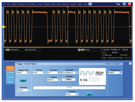
Serial Pattern triggering, a standard feature of the Tektronix DSA models, provides pattern triggering useful to capture data on serial buses at rates up to 6.25 Gb/s. The data in pattern triggering can either be serial (embedded clock) or parallel (separate clock). Serial pattern triggering can trigger on a specified pattern with a length up to 64 bits long or 40 bits long for 8b/10b encoded serial data, providing a tremendously powerful debug tool for many of today’s buses. Figure 16 shows a 111111 PCI Express 5 Gb/s bit stream with 8b/10b encoding.
Pattern Lock Triggering
This feature enables the Tektronix Performance Oscilloscopes to take synchronized acquisitions of a long serial test pattern with outstanding time base accuracy.
When conducting Jitter and Timing Analysis, Pattern Lock triggering can be used to identify and remove random jitter from long serial patterns. With support on data rates up to 6.25 Gb/sec, Pattern Lock triggering helps isolate specific bit transitions and assists in data averaging in conjunction with mask testing. It is available on DSA70000 (standard) and MSO/DPO70000 (option PTH) Performance Oscilloscopes.
Serial Lane Violation Triggering
Multi-lane high-speed serial communication links work effectively only when the lanes are time aligned within specific tolerances. Oscilloscopes are sometimes used to measure the time skew between lanes by triggering on a single character in one data stream and observing the amount of skew time among the lanes. However, these basic measurements do not confirm that the lanes remain time correlated in the longer term.
The Serial Lane Skew Violation Trigger solves this problem by triggering on out-of-tolerance time skew between any two lanes. Pass/Fail tests for lane skew violation may be performed by using the Pinpoint trigger system Dual A & B Triggering with Reset. The oscilloscope triggers on out-oftolerance time skews between the lanes over any period of time: minutes, hours, and even days or longer. Any events that violate the skew time can be captured on the display and counted using the acquisition counter.
The first trigger event (A-Event) from Lane 0 is a comma character and is captured using Width trigger, the second trigger event (B-Event) on Lane 1 represents a comma character is also qualified using Width. The specification requires that the same event on Lane 1 must occur no more than 24.8 nsec after the event on Lane 0. Delay is used to setup a minimum time to start looking for Event B and the Reset Trigger is set to 24.8 nsec, the specification tolerance.Figure 17 shows the oscilloscope triggering on a lane skew violation
Beacon Width Violation Triggering
Serial communication devices based on standards often announce their presence on a communication channel at power up by emitting a "beacon" signal comprised of special packet headers and variable length data blocks. When the device powers up into an error condition, the beacon signal contains additional information and persists for a longer period of time. In the past, it has not been possible to trigger when these variable-length beacon signals violate the limited width.
With Pinpoint triggering and its full-featured A and B event definitions this problem is solved. The A-Event detects the K28.5 comma character in the beacon signal header packet by triggering on the Width of the five ones or five zeroes in the K28.5 character. The trigger holdoff is set to be greater than the beacon signal width so the A trigger event only occurs at the beginning of the Beacon signal.
The B-Event notes the end of the beacon signal by using the Timeout trigger to detect the idle state of the signal.The beginning of the beacon width violation time window is defined by the end of the Trig Delay time which is the Beacon width specification. The end of the beacon width violation time window is defined by the reset time out. With this trigger setup, the oscilloscope will trigger only when the end of the beacon signal occurs within the violation time window. Figure 18 shows a beacon signal that fails a minimum 3.0 millisecond specification.
8b/10b Serial Bus Trigger and Decode
Bus decode and trigger capability is available to decode 8b/10b data automatically from the acquired waveform, a high-speed serial signal, shown at the bottom of Figure 19.A listing of the decoded symbols is also provided on the oscilloscope's display, enabling easy validation of the digital data alongside its analog representation. The 8b/10b trigger and decode capability will work with any 8b/10b data pattern up to 30 Gb/sec, given the 70000 Series oscilloscope has the proper bandwidth setting for the higher data rate.

The 70000 Series Oscilloscope with this bus trigger and decode capability can be set up to trigger on any four symbols (forty bits) of the 8b/10b data stream, and it can trigger on specific header or data packets along with hexadecimal and binary formats of the bus. This is a Serializer/Deserializer (SerDes)-based trigger that can also respond to disparity and character errors in real time.
Trigger-Qualified Jitter Analysis
Most serial transmission standards call for a BER (Bit Error Ratio) of one part per trillion or better. In engineering shorthand, this is known as 10-12 bits. Serial validation measurements on timing, amplitude, and jitter behavior can be made using DPOJET™ Jitter, Timing and Analysis software.
This toolset is a standard feature in the DSA70000 Series, where it resides within the Analysis menu, and it is optional on the DPO7000 and MSO/DPO70000 Series. DPOJET software uses the "spectrum" approach to provide an estimate of total jitter at 10-12 BER.

DPOJET software can perform its analysis on either an arbitrary pattern or a repeating pattern. Test patterns for signal integrity measurements are developed by industry groups in order to standardize measurement methods and to stress the device under test with worst-case scenarios. It is often desirable to make a jitter measurement on a specific section of the waveform. Trigger qualification is the key to implementing this procedure.
Consider the example of a Lone Bit Pattern (LBP) from a Serial ATA II device. The LBP is a defined set of words that contains a "lone bit" 00001000 that differs from all those that surround it (such as 00001000). Assuming a bit interval of 333 ps, the 00001000 lone bit expression equates to a negative pulse of 1.33 ns duration followed by a positive pulse of 333 ps and finally a negative pulse of 999 ps duration. To perform triggerqualified jitter analysis, it is necessary to distinguish the lone bit pattern as a unique entity within the data stream.

With a stable trigger on the LBP, it is now possible to perform the jitter and eye analysis on as many consecutive triggers as need. Figure 22 shows the resulting RT-Eye analysis of the LBP pattern.
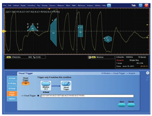
Visual Trigger
This optional feature provides an intuitive method of triggering based on shapes in the oscilloscope's graticule. It enables the 70000 Series Oscilloscope user to define shapes as shown in Figure 22 on the oscilloscope's display that serve as trigger events for the incoming signals.
Areas can be created using a variety of shapes including triangles, rectangles, hexagons or trapezoids to fit the area to the particular trigger behavior desired. Once shapes are created on the oscilloscope's display, they can be positioned and/or re-sized dynamically while the oscilloscope is in run mode to create ideal trigger conditions.
The accuracy behind visual trigger is limited only by the resolution of the current time/div and volts/div settings on the oscilloscope's display. For example, the minimum width or height of a visual trigger zone can be one screen pixel.Translating pixels to voltage or time is a matter of dividing the total time or voltage scale setting on the instrument by the display's pixel count (1000 for horizontal and 500 for vertical).
Visual triggers can be combined with the Tektronix Pinpoint Trigger System defined earlier and act as a boolean logic qualifier for an "A" event described earlier.
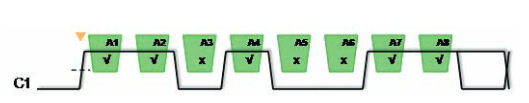
Visual triggers can speed up complex debugging situations for high speed serial signaling by creating a series of ones and zeros using up to 8 shapes that simulate a serial pattern trigger (see Figure 23). This becomes a serial pattern trigger accomplished in Visual Trigger and can be customized to support any possible data rate or unique coding scheme desired by the oscilloscope user.

For DDR debugging situations, Visual Trigger can be helpful for accurately capturing bursty read/write traffic (see Figure 24) and detecting patterns in the memory data buses by using the dynamic shaping of Visual Trigger to localize causes of reduced setup and hold margins on memory controller traffic. The flexibility in the sizing and movement of those shapes speeds up the verification process.
The visual trigger option adds an additional dimension to Pinpoint Triggering and the 70000 Series Oscilloscope trigger system.
Advanced Search and Mark
Advanced Search and Mark is a powerful tool that complements and enhances the capabilities of the Pinpoint trigger system for designers coping with signal integrity and timing challenges. Used together, the Pinpoint trigger systems and Advanced Search and Mark provide unprecedented flexibility and increases precision for locating points of interest in a signal. This translates to more efficient debugging and greater insight in waveform analysis.
Advanced Search and Mark (ASM) uses most of the same trigger types as the Pinpoint trigger system to analyze acquired waveforms and identify events of interest. While hardware triggers watch for one event type at a time, ASM scans for multiple event types simultaneously. For example, it can scan for setup or hold time violations on multiple channels. Another example is simultaneously scanning starts and stops of bursts like reads or writes on DDR memory data waveforms. Coupled with high sample rate, ASM scans provide finer resolution than hardware-based trigger methods when working at high signaling speeds. And, it can apply trigger searches on math waveforms which have applied functions, such as filtering or spectral analysis, on the acquired waveform.
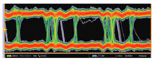
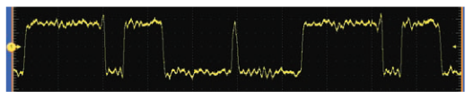
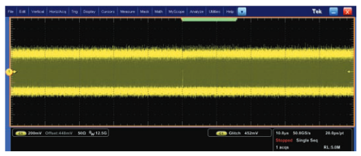
Figure 25 introduces the ASM features and benefits in a typical debugging scenario. The screen display is a FastAcq visualization of the waveform that reveals potential problems with a signal. Infrequent events are shown in the grey traces and occasionally there are misplaced edges seen in the waveform.
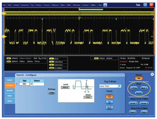
Suspecting glitches or corrupted signal transitions, the Pinpoint trigger system is used to isolate pulses narrower than expected in the system. In doing so, a glitch event is detected, as shown in Figure 26.
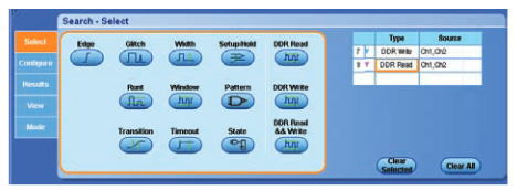
Next, ASM is used to further understand what is going on and provide clues to root cause. As can be seen in Figure 27, search methods corresponding to each Pinpoint trigger type are available to scan the acquired waveform. The palette of search methods is suitable for isolating a wide variety of signal integrity defects and issues including setup and hold time violations. In Figure 28, Glitch is selected from the Search menu and a user proceeds to configure parameters for this search.
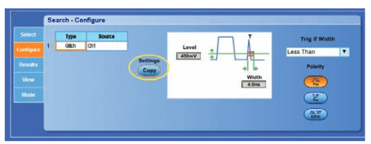
The Pinpoint trigger system is integrated with ASM so that the trigger settings in one can be quickly applied to the other. In this case the Settings Copy feature is used to directly copy settings from the Pinpoint Glitch Trigger into the ASM Glitch Search at the touch of a button. This saves time and reduces mistakes when moving between the real time trigger system and post-processing search features.
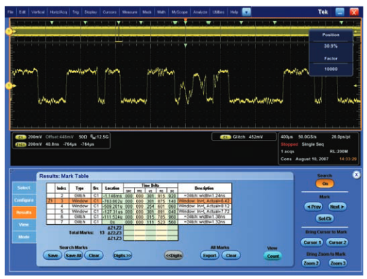
Now that a Search is defined with the Glitch trigger, the display updates to indicate matching locations in the waveform. Figure 29 shows results for a 5 Megasample waveform. A search for positive pulses less than 4 ns wide was performed.
The block of light green symbols at the top of display above the waveform (Figure 29) is actually a collection of individual Marks placed by ASM indicating events that meet the search criteria. Although the waveform looks uniform, ASM has found many matches for the Glitch condition. They start at centerscreen because that is the trigger position on the display and is the first point at which the Pinpoint trigger detected the first Glitch with the same criteria
In Figure 30, display zoom is used to examine one of the marks in more detail. The Previous and Next navigation controls at the right-hand side of the screen select a mark for viewing. The upper part of the display shows the entire acquisition record of 5 million samples spanning 100 μs duration in this case.
The lower view of the scope display (Figure 30) shows the waveform at Mark 2 centered in the Zoom display region. It spans just 1 μs duration to show the area around Mark 2 in more detail. The zoom factor can be increased to provide additional detail or decreased to include more of an overview.In this case Marks 1 to 4 can be roughly compared. Notice the apparent periodicity of these events, a potential clue to their cause.
Traditional hardware trigger systems focus on one set of signal characteristics at a time and exclude other conditions so isolating a variety of faults usually requires sequencing through different trigger types. Tektronix Search and Mark complements the Pinpoint trigger system with the ability to perform multiple searches simultaneously so multiple conditions on multiple signals can be detected efficiently.
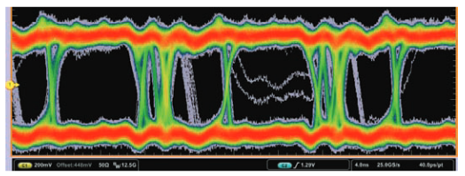
Figure 31 illustrates how multiple search methods within ASM can be applied to a signal to simultaneously scan for faults.ASM allows up to eight searches applied simultaneously so a variety of events can be detected on one or more waveforms.FastAcq has revealed signal issues including misplaced edges and occasional transitions that linger too long between thresholds or never complete.

In Figure 32, Glitch and Window searches have been selected from the Search palette and appear in the table at the right.Up to six more searches can be defined and applied to Channel 1 or other channels. This enables a user to scan multiple channels for multiple fault conditions without having to reconfigure. Each search can have unique settings so for example, additional Glitch searches could be defined for Ch1 but with different threshold or width values.
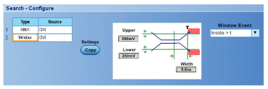
The Window search is defined using controls similar to those in Glitch search. In Figure 33, the Window trigger is configured to catch signals that cross into the region defined by an upper and lower threshold and remain inside for more than 5 ns.Other forms of Window search can detect signals that travel outside a specified region, such as excess overshoot above or below a signals normal range.
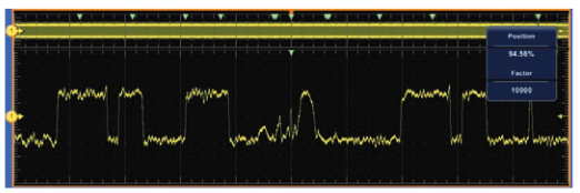
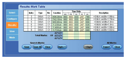
Figure 34 shows the results of applying these two searches.Notice the green marks at the top of the screen indicating where any search criteria have been met. In this case a user has navigated to the last mark to view it in a zoom view. Figure 35 is the Results table for these two searches. Notice the mix of Window and Glitch events found, along with time locations and descriptive information.
Besides its capabilities to exchange settings with the Pinpoint trigger system and enhancing productivity by finding repetitive and complex events in long record acquisitions, Advanced Search and Mark provides many more features that deliver beneficial results to its users.
The Results Table of ASM, as shown in Figure 36, is an efficient tool to summarize trigger events, navigate to each event in long records, and calculates precision timing measurements over large intervals.
ASM includes the capability to stop waveform acquisitions when an event is found. This enables it to operate as a pseudo-trigger mode whereby waveform data is acquired and scanned using one or more search methods. If at least one match is found, acquisition stops and a Mark is placed to indicate each match. If no match is found, another record is acquired (assuming Run Continuous acquisition mode) and the process repeats.
Thus, ASM can be used to scan live or Math waveforms and act as a pseudo-trigger. This operating mode does not have the vigilance of a hardware trigger because it takes longer than hardware-based trigger detection to perform software-based post-processing to look for events, but ASM search methods offer additional flexibility and precision when events frequently occur.
Conclusion
The earliest Tektronix breakthroughs in triggering technology established the oscilloscope as an indispensable quantitative tool for observing electrical activity. Today’s oscilloscope applications range from capturing random events of just a few picoseconds’ duration to long-term monitoring and analysis. All of these applications depend on powerful, versatile triggering features.
The complex signaling used in modern computing, serial data transmission, and communications systems calls for continuing advancements in trigger capability. Answering this call, the Tektronix Pinpoint trigger system keeps up with the fastest, most complex signals thanks to innovative trigger features such as Dual A- and B-Event Triggering, Window Triggering, Logic Qualification, and Reset Triggering.
Advanced Search and Mark complements the Pinpoint trigger system, as wells as other core features of the DPO7000 and MSO/DPO/DSA70000 Series. Used in conjunction with Pinpoint triggers, sample rate, deep acquisition memory, and FastAcq visualization, Tektronix oscilloscopes provide the most powerful and efficient solution for signal integrity analysis and system debugging available among high performance oscilloscopes available today.