Introduction
Although high-speed digital technologies have opened up new technological possibilities and enabled widespread innovation, they have also created several problems for the design engineers who must characterize and troubleshoot them.
Chief among these problems are infrequent or intermittent events, such as serial data packets, laser pulses or metastability. Difficult to identify and characterize, these events require test and measurement equipment that offer both high sample rate and extended data capture.
This places extreme demands on oscilloscope performance, which has historically necessitated a compromise between resolution and capture length. All oscilloscopes have a finite amount of memory depth; using higher sample rates fills the instrument’s memory more rapidly and decreases the time window of data acquisition. Conversely, capturing data over long periods of time has typically come at the expense of horizontal timing resolution (sample rate).
With the high sample rates and bandwidths of today’s oscilloscopes, the critical issue is now optimizing the quality of information captured by the oscilloscope. This includes:
- How to capture multiple events at a sufficiently high horizontal resolution for effective analysis
- How to optimize the use of memory by storing and displaying only the necessary data
Fortunately, advanced Tektronix oscilloscopes featuring FastFrame™ Segmented Memory remove the necessity of compromise by improving the efficiency of memory usage and quality of data acquisition.
Using Record Length to Your Advantage
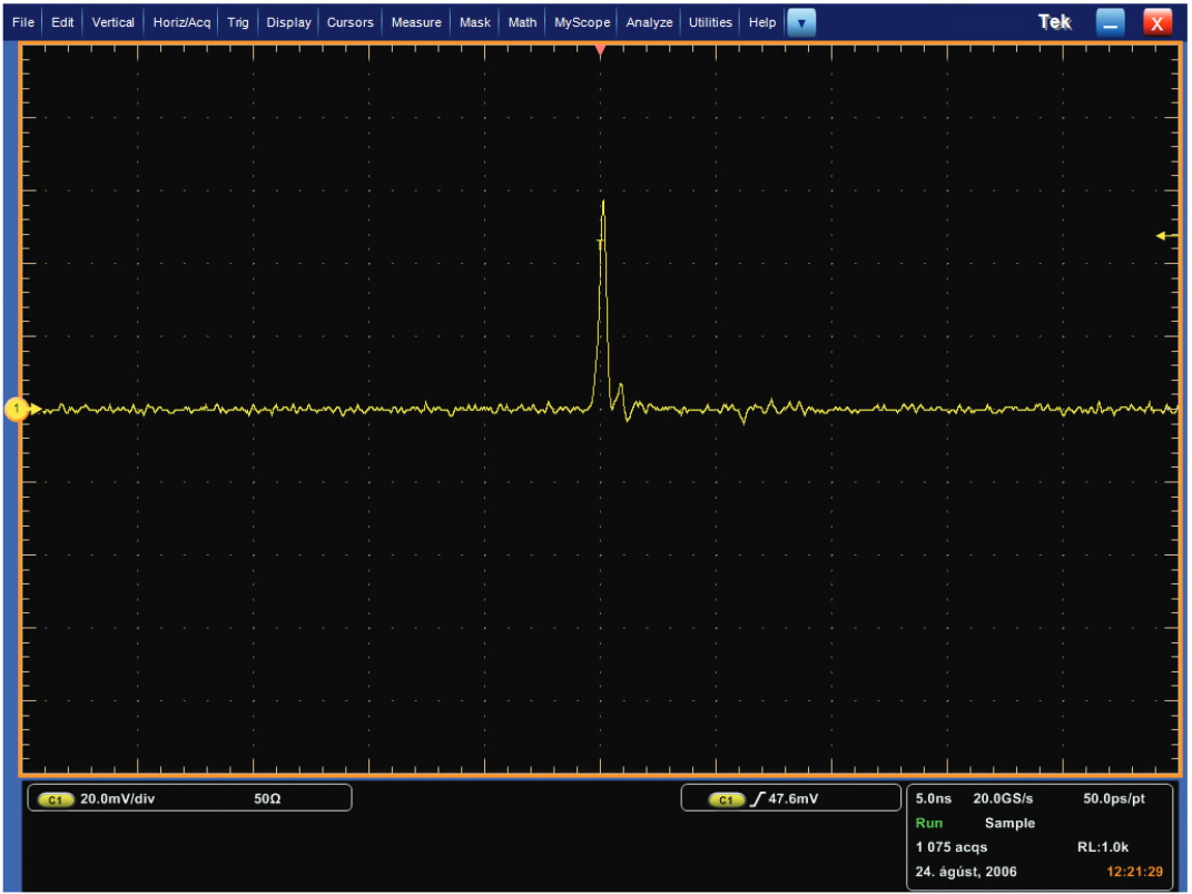
Consider the single pulse shown in Figure 1. It was acquired in a 1000-point waveform at a sample rate of 20 GS/s on a Tektronix DPO7254 digital phosphor oscilloscope. At this sample rate, much of the waveform detail can be seen.
If, however, you want to view several consecutive pulses, the time window of acquisition must be increased, requiring concessions to be made. To fit within the instrument’s available memory, either the sample rate must be decreased or the record length of the time window increased. Of course, lowering the sample rate inherently sacrifices horizontal timing resolution.
Alternatively, you can extend the record length, allowing an increase in the acquisition time window without sacrificing sample rate. But this method also has its limitations. Despite advances in memory technology, high-speed acquisition memory is still a precious resource. And it can be difficult to discern how much is enough. Even with what one might consider to be a long record length, you may still not be able to capture that last, and perhaps most critical event.
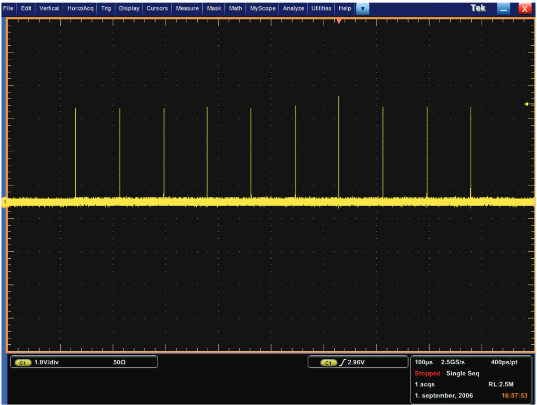
As you can see in Figure 2, the time window was extended by 10 times to capture more consecutive pulses. This was accomplished by increasing the time of each division of the graticule displayed on the screen in conjunction with an increase to the record length, while holding the sample rate constant. This larger acquisition comes with some disadvantages:
- Larger acquisitions increase the storage requirements in NVRAM and on disk drives
- Larger acquisitions affect I/O transfer rate (i.e., GPIB throughput)
- More record length translates into additional costs for the user Because the oscilloscope has more information to process, the period of inactivity, or “dead time,” between acquisitions increases, resulting in a decrease to the update rate
With these trade-offs in mind, you must continually balance the need for high sampling rates with the available memory length per channel.
Segmented Memory Architecture
Many strategies have been formulated to solve this problem. One popular method is the “Segmented Memory” scheme. Instruments equipped with this memory technique – such as Tektronix oscilloscopes featuring FastFrame™ Segmented Memory – allow you to divide the available memory into a series of segments. Each segment is then filled with a triggered acquisition at the desired sample rate.
By carefully defining trigger conditions, this technique allows you to capture only the waveform, or waveform segment, in which you are interested. Each captured event is then stored in its own numbered memory segment. Multiple memory segments, or frames, can then be viewed individually in the order they were captured, or layered to show their similarity and contrast. This feature essentially allows you to scan through unwanted sections of the waveform so you can focus on the signal of interest.
Figure 3 illustrates this approach. Using FastFrame Segmented Memory in the DPO7254 oscilloscope, the pulses are captured at a sample rate of 20 GS/s with the same small record length as shown in Figure 1. The segmented memory has been overlaid so all of the pulses appear stacked on top of one another on the screen. Advantages of this approach include:
- The high waveform capture rate increases the probability of capturing infrequent events
- The waveform detail has been preserved by using high sample rates
- The pulses were captured without the dead time between them, ensuring efficient use of the record length memory
- The segments can be quickly and visually compared to determine if an anomaly “sticks out” of the overlaid stack
Frames and Frame Sizes vs. Record Length
Tektronix oscilloscopes with FastFrame Segmented Memory allow you to partition the available acquisition memory into frames (memory segments) of hundreds of thousands of samples. This capability facilitates a burst trigger rate of 310,000 frames per second (acquisitions/sec), which equates to a maximum dead time of 2.5 microseconds – a significantly faster trigger rate than that of most other oscilloscopes.
When activated, FastFrame Segmented Memory automatically computes and selects the record length needed to accommodate the number of frames and points per frame (frame length) you select. Based on the available memory of the instrument, it then computes the product of the number of frames and frame length, and selects the nearest record length to determine the number of frames that will fit the available memory.
Each frame can be viewed individually and you can scroll through them by selecting frame numbers with a mouse, virtual keypad or the multi-purpose knob on the instrument’s main console. When a particular frame of interest is identified, you can use the instrument’s features to characterize, measure, zoom and analyze the waveform in detail.
To quickly see anomalies that stand out from the common shape of the waveform, multiple frames can be overlaid to show common and outlying points. The “View Multiple Frames” option in FastFrame Segmented Memory overlays the selected number of frames using color to highlight how frequently the points are overlaid on each other. Red points indicate a frequent rate of occurrence, and blue points are less common.
Averaging/Enveloping of Frames
FastFrame Segmented Memory supports the standard “Sample” acquisition mode, as well as advanced modes including “Peak Detect” and “Hi-Res”. Selections in the “FastFrame Setup” menu provide a "Summary" frame at the end of a record for “Envelope” or “Average” modes. This “Summary” frame graphs the waveform using the envelope points (maximum and minimum values) or average points of the selected number of frames.
For example, when the “Average” mode is used with FastFrame Segmented Memory and the frame count is 10, the oscilloscope calculates the average of the first 9 frames and displays the averaged waveform in the last, or “Summary,” frame. If the “Envelope” mode is used with FastFrame Segmented Memory, the oscilloscope computes the maximum and minimum values of all waveforms in the 10 frames and displays these values as an enveloped waveform in the last frame. (If the acquired waveform data for a selected frame fills the record length, the last frame is deleted and replaced with the averaged or enveloped frame.)
Time Stamping of Acquisitions
The waveforms in each of the frames tell only part of the story. There is also important information embedded in the timing of each of the frames. Each of the trigger points possesses timing information, which is called a time stamp. By analyzing the time stamps, you can determine when each event occurred, as well as the relative time between events.
Time Resolution
The timing of the trigger is captured with extremely high resolution. By a process of time interpolation, the trigger timing is resolved to a small fraction of the sample interval. At high sample rates, this can be less than a nanosecond. Although this resolution may not be interesting for time stamping an individual event, it is a very powerful tool when measuring time intervals between many events.
FastFrame User Interface
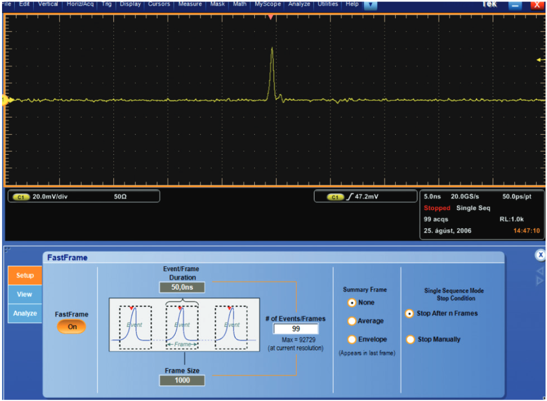
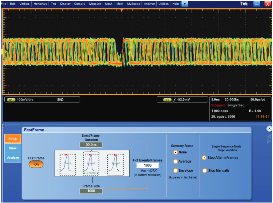
When FastFrame Segmented Memory is on, the first section or “tab” of the control panel gives the basic options for defining and navigating an acquisition. It has controls to turn FastFrame Segmented Memory on and off, and allows you to select the frame length and the number of frames. It also offers the option to include a “Summary” frame (“Envelope” or “Average”).
Because Tektronix oscilloscopes provide large record lengths, FastFrame Segmented Memory acquisitions can produce thousands or, in some configurations, over a million frames. The “Single Sequencing Mode Stop Condition” option on the first tab’s menu enables you to stop acquisitions after the last frame is filled, or by a manual press of the “Run/Stop” acquisition button on the oscilloscope’s console.
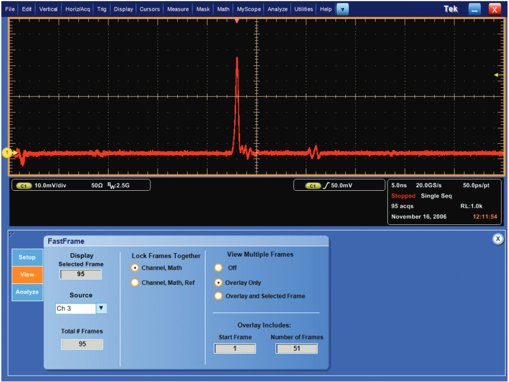
The second section, or “View” tab, of the FastFrame Segmented Memory menu is used to define and control how the frames are displayed. It controls:
- The input source that will be the focus of the FastFrame Segmented Memory acquisition
- Whether to view waveforms from “Input” channels or “Math” channels, with or without the “Reference Waveform” channels
- Viewing multiple frames in overlay fashion
Possible input sources for FastFrame Segmented Memory are the data “Input” channels, the “Math” channels and the “Reference Waveform” channels of the oscilloscope. In selecting a primary source, you focus on a particular aspect of a potential problem in the device under test. The source channel might be the signal that is known to display an error, or you might change the focus by switching to another channel that is suspected of causing interference. In both cases, the waveform in the source channel frame is viewed with the waveform of the other channels in the same timeframe.
The “Lock Frames Together” control determines whether “Input” channels and “Math” channels will be viewed with or without the comparable timeframe of the “Reference Waveform” channel. For example, FastFrame Segmented Memory always displays the frames of the “Input” channels and “Math” channels together since, by mathematical definition, they are intrinsically locked. However, the “Reference Waveform” may be entirely different, so it may or may not be desirable to view it alongside the “Input” and “Math” channels in the same timeframe. FastFrame Segmented Memory enables you to choose whether to lock the view of the “Input” and “Math” frames with the comparable view of the “Reference Waveform.”
The “View” tab also controls the display of individual frames or the overlay view of frames. If the frames are overlaid, you can overlay all of them or just a few by selecting the desired sequence of frames. You may want to select a reference frame from anywhere in the population of frames, and overlay a subset of the frames over it. For example, if frame number 12 (out of a population of 100) is the selected frame of interest, you can overlay and compare it to the sequence of 20 more frames starting at frame 13. The reference frame can be any frame, but is often the first frame in the acquisition.
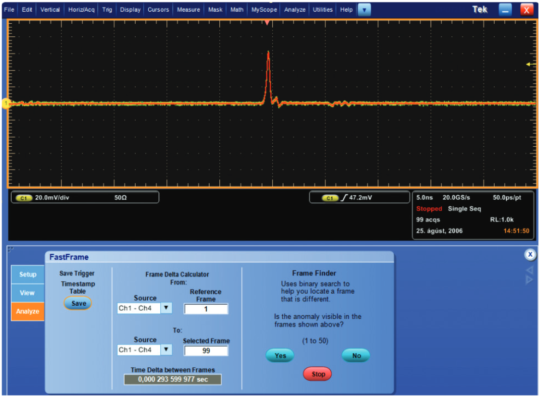
On Tektronix MSO/DPO5000, DPO7000, and MSO/DSA/DPO70000 Series oscilloscopes, the third section, or “Analyze” tab, of the FastFrame Segmented Memory control menu provides three methods to analyze the FastFrame results. “Save Trigger Timestamp Table” records the time stamps for the reference frame and the selected frame(s) as well as the time difference between the reference and each subsequent frame. The time stamps are displayed in a format that shows date (day, month, year), clock time (hours, minutes, seconds) and fractions of seconds (milliseconds, microseconds, nanoseconds, picoseconds). This is valuable information for data logging and analysis using Excel, MATLAB or custom applications that can read comma-delimited data points.
The “Frame Data Calculator” performs a similar function as the “Save Trigger Timestamp Table.” However, it does not save the data to a separate file, but displays it in the field labeled “Time Delta between Frames.” This is the time difference between the selected reference frame from any signal source and the selected frame from the same or another source.
The third tool in this menu is the “Frame Finder.” When an overlay of frames is selected, the “Start” button of this tool divides the selected frames into smaller groups of frames. As it displays each of the smaller groups, you determine whether the frame of interest is in the displayed group. By narrowing down the selection, the “Frame Finder” enables you to drill down to the frames of interest from a large selection, without viewing each frame individually
Applications
Finding Abnormal Events in a Serial Signal
Designing and debugging complex systems are more challenging than ever due to the increased speeds of serial communication protocols. Small abnormalities that disturb communication circuitry are more prevalent and harder to find and isolate than ever before.
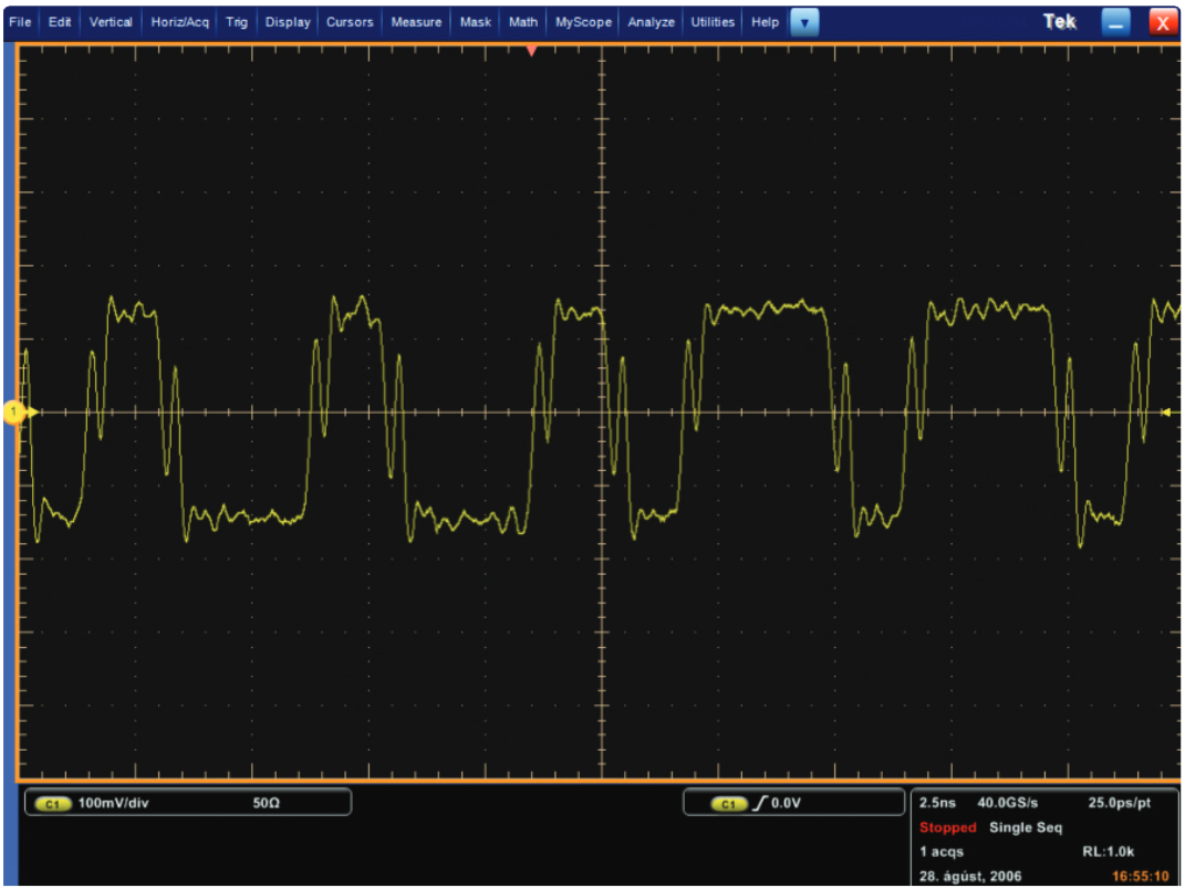
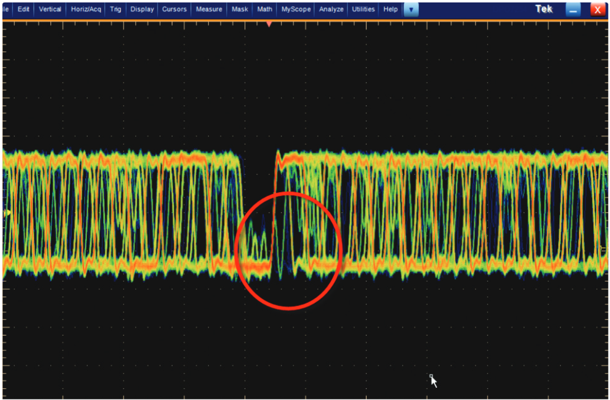
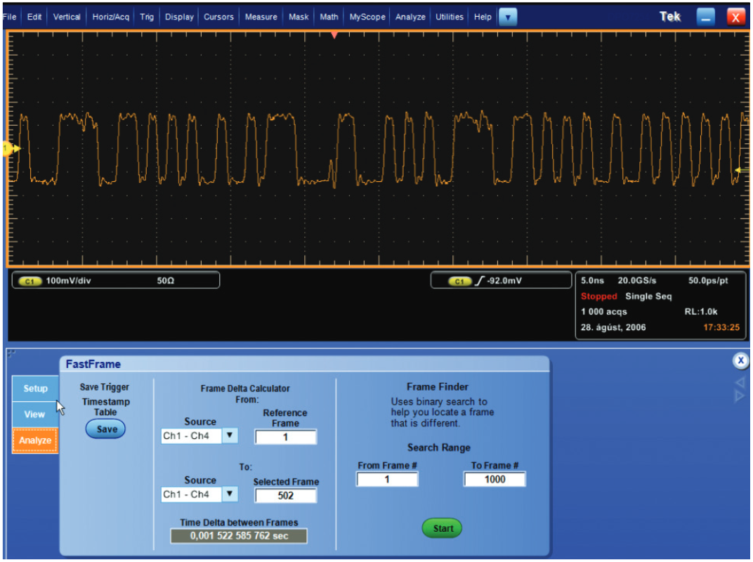
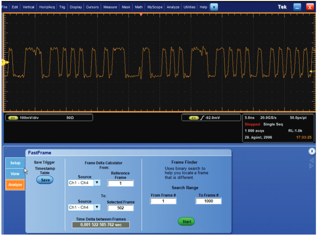
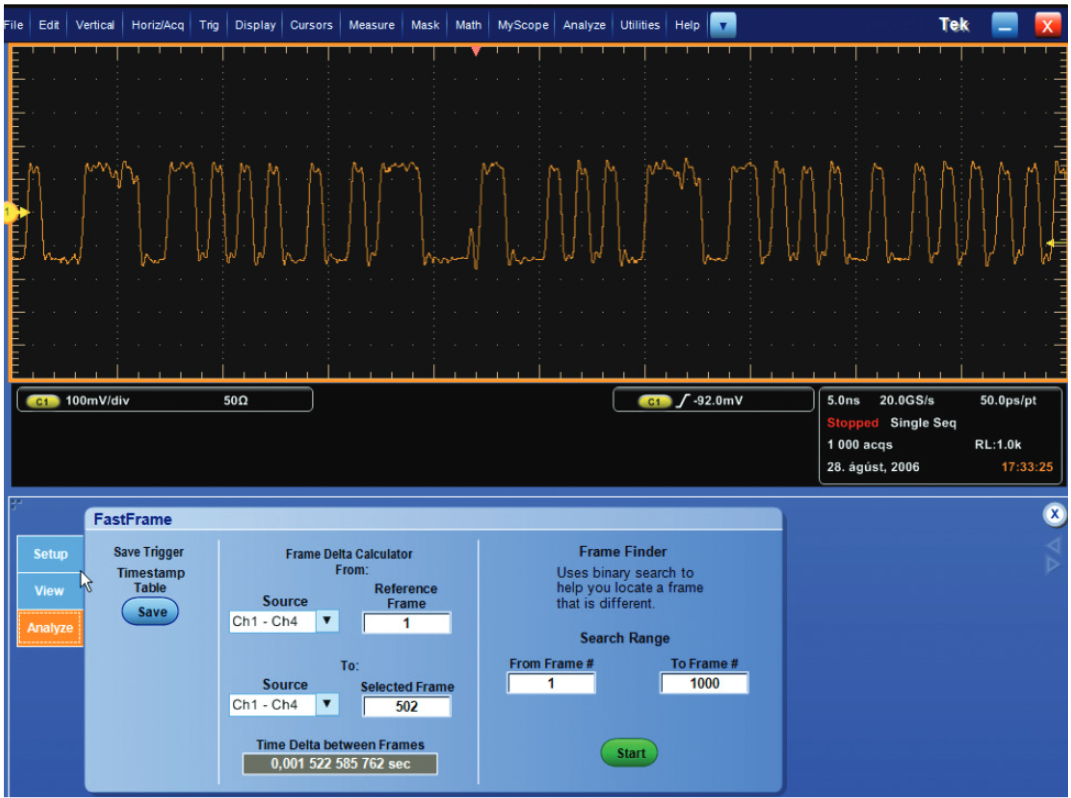
Figure 6 shows a serial communication signal on a Tektronix DPO7254 oscilloscope. An encoding error is suspected to be in the signal.
The high sample rate and long record length of the DPO7254 enable it to capture a large number of data points over a sufficiently long period of time, which increases the probability of identifying elusive abnormalities in the signal. And through the use of its “FastAcq” high-speed waveform acquisition mode and FastFrame Segmented Memory, the instrument quickly provides visual clues of waveform elements warranting further investigation.
With FastFrame Segmented Memory, 1000 frames of the signal are captured while maintaining a high sample rate as well as suitable time/div and record length settings. The frames can be scrolled through individually; however, this process can be time-consuming and tedious for 1000 frames. To expedite a comparison of the frames, an overlay of all frames displays occurrences of frequency through color coding. This allows you to quickly and visually see frequency abnormalities within a waveform, pinpointing areas for further analysis.
Using the “Frame Finder” on the “Analyze” tab, you can now dissect the layered frames by visually focusing on the infrequent (i.e., blue) frames and eliminating the others from the layers. What’s left is one, or a few, frames for further investigation. Any of these frames can be designated in the “Display Selected Frame” viewing field. Using a mouse wheel or the instrument’s multi-purpose knob, comparisons of a selected frame with others is a greatly simplified process. Time stamp data is also easily accessible on the screen using the “Frame Delta Calculator,” or you can save a complete timestamp table for offline analysis.
Comparing Infrequent Phenomena - Pulse Waveform Characteristics
FastFrame Segmented Memory is ideally suited for testing pulse waveforms, such as those utilized for laser applications. In these environments, the waveform is a sequence of pulses that are largely the same, yet irregular pulses can sporadically crop up. Also, these pulses are separated by large intervals of inactivity in the signal, which consume memory when contiguous acquisitions are taken.
For these circumstances, FastFrame Segmented Memory can be used to capture the appropriate number of pulses to complete an analysis, while eliminating the “dead time” intervals between them. This saves memory, and still enables you to capture each of the pulses at high horizontal resolution.
To use this function, select “FastFrame Setup” from the horizontal menu and set the frame length at 1000 points with a frame count of 10. We’ve elected to start with the “Average” summary frame to capture the average maximum and minimum values of the pulses over the series of acquisitions. When FastFrame Segmented Memory is turned on and the “Single Sequence” button is pressed, the instrument acquires 10 pulses and displays the first acquisition frame. Switching to the “View” tab, you can scroll through each of the frames by incrementing the number in the “Selected Frame” field. The last frame shows the waveform constructed from the average of the previous frames. This frame could have also been the “Envelope” summary frame, containing the collection’s highest and lowest values.
Whereas a standard acquisition would use up available record length by including the interval time between each pulse, FastFrame Segmented Memory captures only the pulses in the available memory and with ample sample rate resolution. Also, the fast waveform acquisition rate of the FastFrame Segmented Memory mode decreases the chance that anomalies will be missed between acquisitions.
Each pulse is now displayed sequentially and with high horizontal resolution and sample rate. By selecting the “Overlay” option and setting the “Number of Overlay Frames” to 10, you can immediately see that there are variations in the points between the acquired frames. As the previous example illustrated, you can find a unique frame that contains outlying points using the “Frame Finder.” Once the frame of interest has been identified, you designate it as the “Selected Frame” so it can be the frame of reference for further analysis and quick comparison with other frames.
Debugging Errors with Time Stamps - Intermittent Microprocessor Interrupts
FastFrame Segmented Memory can provide a different type of functionality for digital designers. For example, if your processor system is being infrequently interrupted, it can be difficult to gather timing information with an oscilloscope. If you don’t know when or how frequently the event will occur, you can’t set up the instrument in normal acquisition mode and be assured of capturing the information you need.
FastFrame Segmented Memory can do this easily. In Figure 10, the active high interrupt strobe is measured to be roughly 100 nanoseconds wide, so we set up the oscilloscope to capture 100 frames of 1250 points. In this example, the shape of the pulse is not of particular interest. We are, however, interested in the time of the pulses’ rising edges.
After turning FastFrame Segmented Memory on and selecting “Single Acquisition” to capture 100 frames, you use the menu in the “Analysis” tab to compare the time stamp data at the trigger point. These time stamps are displayed on the screen in the “Time Delta between Frames” area on the “Analysis” menu (See Figure 10). The “Reference Frame” was chosen to be the first interrupt pulse and the “Selected Frame” (displayed on the screen) is the fourth pulse. The time difference between these pulses is shown in “Time Delta between Frames.”
The time stamps of all the frames can be output in tabular form for in-depth analysis using Excel or a wide variety of other popular software tools that read comma-delimited files (.CSV). These files include selected time stamp data as shown in Table 1.
| Frame Number | Date of Acquisition | Time of Acquisition (ps resolution) |
| 1 | 31 Aug 2006 | 14:25:42.806 454 372 165 |
| 1 | 31 Aug 2006 | 14:25:42.806 514 372 136 |
Comparing Intermittent Events - Metastability
In digital design and test applications, intermittent timing differences between a data signal and its clock can be difficult to detect. Since the setup and hold violations often occur infrequently, capturing a series of these events with sufficiently high sample rates typically requires very long memory. However, with FastFrame Segmented Memory, you can isolate a number of these events from the rest of the signal at the desired sample rate.
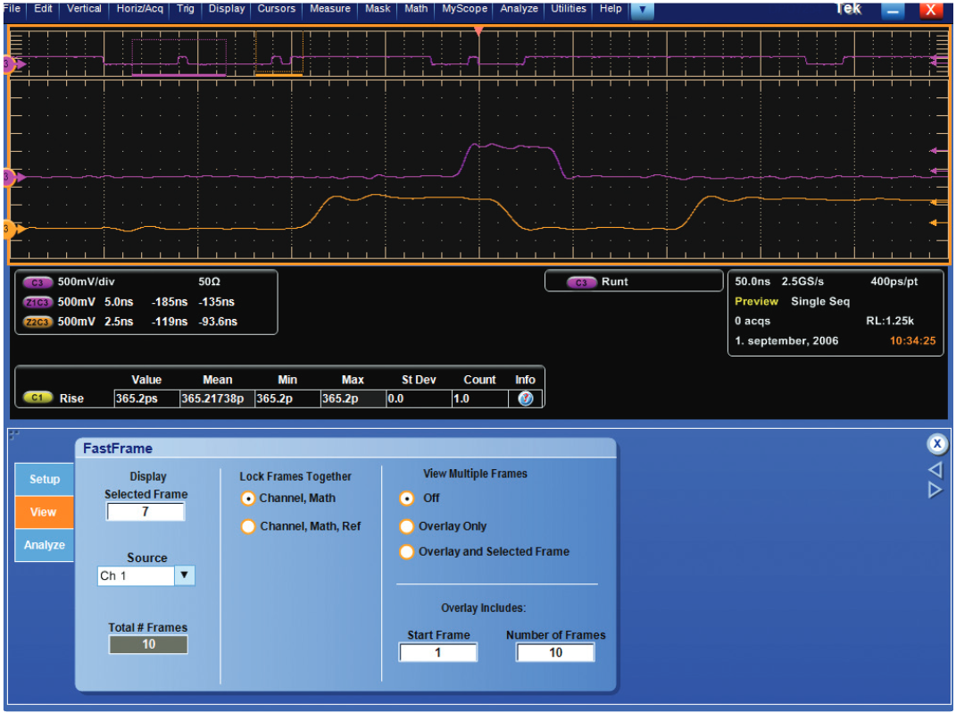
In this example, we’ll examine the operation of a flip-flop in a circuit. We’ve connected a data input signal to Channel 1 of a Tektronix oscilloscope, the clock to Channel 2 and the data output to Channel 3. Since we want to capture the anomalies caused by setup and hold violations, we define the trigger parameters to catch runt pulses in the output signal. Set the trigger “Type” to “Runt,” the trigger “Source” to “Ch3” and the “Polarity” to either (See Figure 12).
Now, the FastFrame Segmented Memory parameters must be selected. Set the “Frame Count” to 10, which selects a record length of 1250 points. Turn FastFrame Segmented Memory on and enable the single sequence acquisition mode by pressing the “Single Acquisition” button on the oscilloscope console. Using the “Display Selected Frame” control on the “View” tab, you can scroll through the frames to examine the input and output signals at the point of trigger in all of the frames.

By using the multi-channel acquisition capability of FastFrame Segmented Memory, you are able to quickly compare the causes and effects of several suspected setup and hold violations. In this example, we can determine that the problem is a setup violation, where the data signal is getting too close to the rising edge of the clock. In each case, the result is a positive runt pulse (See Figure 12).

We can also zoom in and examine each frame in detail. For example, to compare the first and second runt pulses on Channel 3, dual-window zoom can be used for visual sidebyside analysis (See Figure 14).
Conclusion
In applications requiring both high sample rates and long record lengths, adding more memory is not always the answer. For example, in circumstances where a series of infrequent or intermittent events must be acquired, FastFrame Segmented Memory in advanced Tektronix oscilloscopes provides an ideal means to capture only the necessary events. By segmenting the acquisition memory and providing a trigger and time stamp for each segment, FastFrame Segmented Memory optimizes data acquisition and offers smarter usage of limited memory resources.