Modern standards are moving away from parallel data links to serial data links. Although a serial link needs a much higher data rate compared to a parallel link to achieve the same throughput, designers prefer serial links because of less complexity, lower costs, and the possibility of higher data rates. Parallel busses need a compensation of the delay between each data line and their clock signals. Serial busses have a differential data pair for each direction, their clocks are embedded in the data signal and will be recovered in the receiver. However, the higher frequencies used in high speed serial (HSS) data streams require more focus on signal integrity issues. In addition, debugging of HSS signals is more challenging.
Most HSS signals are already in the range of Gigabits and require very high bandwidth in the physical layer for their links. One way to verify the performance of serial links is compliance testing. Usually compliance tests are used for characterization at a final state of the design. If the compliance test “passes” everything is fine. If not, debugging of the physical layer might become necessary.
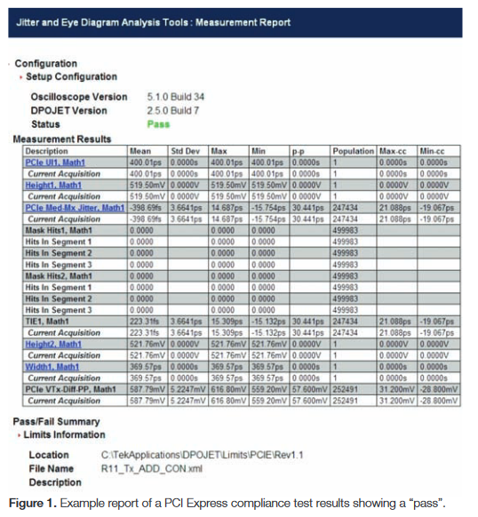
A first step of investigation could be to look for measurements that are out of range related to the appropriate standard’s specifications. The results can enable an experienced engineer to perform further measurements and actions to solve the problem.
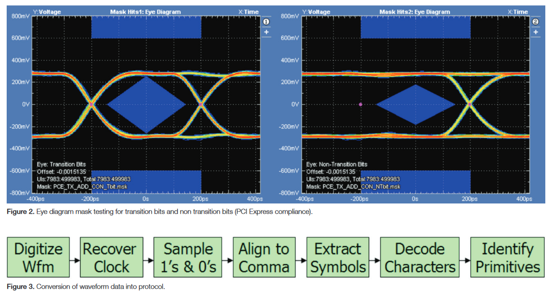
If this does not solve the problem, the engineer can look at a composite of all data values and transitions on the bus using an eye diagram. The eye diagram can show issues related to noise, jitter, and signal integrity. It can also be used to check for violations of an eye diagram mask which are specified in many industry standard compliance tests. Any kind of degradation of the signal will cause less margin or more hits in the eye mask. This degradation can indicate significant problems in the physical layer (PHY) design. Example signal integrity issues that can lead to mask test failures are: slow signal rise time (bandwidth), small signal amplitude (attenuation), large overshoot (inductance), or large jitter and noise components (cross talk, intersymbol interference (ISI), etc).
Debugging Protocol Errors
What can you do if the physical layer (PHY) compliance test passed, but you still see errors in your protocol test? Issues with the PHY layer will often cause intermittent faults. Usually PHY verification and protocol testing are done with different test equipment and under different conditions. Why not use an oscilloscope for further investigation?
To ensure best signal fidelity and highest timing resolution, you should evaluate the link at the compliance test point with an oscilloscope and convert the acquired "analog" waveform into binary values or even characters and commands.
The Tektronix DPO/DSA/MSO70000 series oscilloscopes convert the waveform data into a binary format by recovering the clock first and comparing the voltages with a user-defined threshold and some hysteresis. A block diagram of the software’s processing is shown in Figure 3, with results shown in Figure 4.
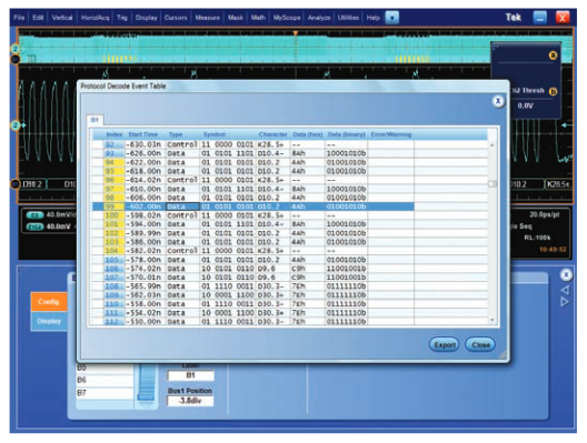
You can see a table that lists the characters and the protocol.The protocol is correlated to characters and to 0s and 1s in the analog waveform. This makes is easy to track errors in the protocol down to the physical layer.
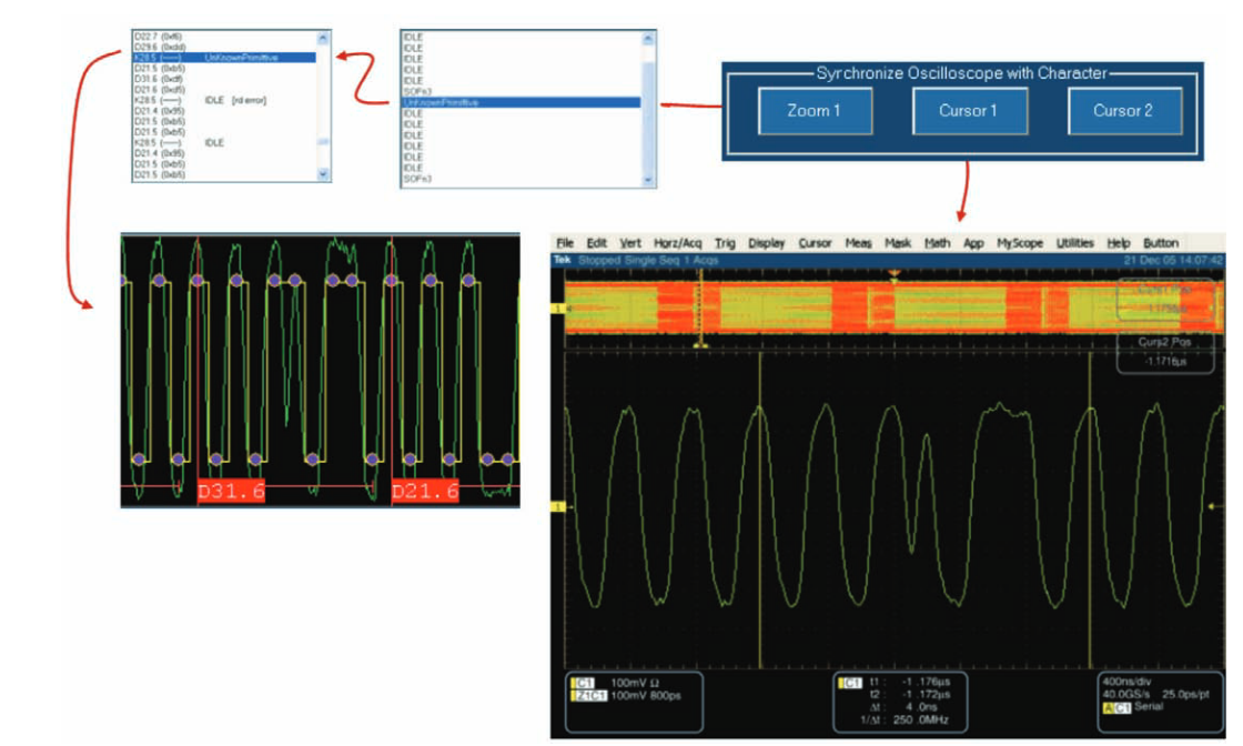
The displayed waveform (see Figure 5) will help you to understand why wrong 0´s and 1´s have been possibly misinterpreted by your receiver. Cursors and the oscilloscope's zoom window can be synchronized with the scope waveform display and can help you to find the cause of the protocol error
Capturing Specific Data Values
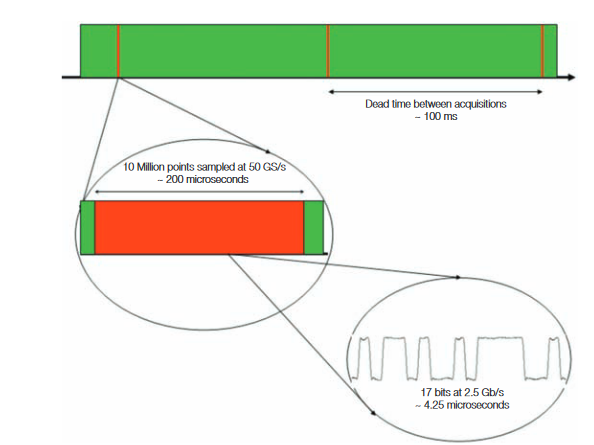
Searching for a specific character in the protocol table is a common method to locate protocol errors in the data stream. But searching is a post acquisition process and is limited to a time frame that is set by the size of the acquisition memory. The dead time between acquisitions is quite large and is caused by oscilloscope and the processing time of the software for interpreting the waveform into binary and then searching for the character. See Figure 6.
Therefore the chance of capturing any infrequent and rare faults is very low. For example if you have 10 million points sampled at 50 Giga samples, your real time acquisition will stop after 200 microseconds. But it will take hundreds of milliseconds before the system can capture the next block of 10 millions points. Larger memory will even increase the problem. If you really need to find rare events, you have to trigger on those faults.
Most digital oscilloscopes provide a large portfolio of triggering capabilities. Traditionally, troubleshooting is related to time and level qualified triggering. With the advanced trigger modes available on today’s oscilloscopes, it is easy to trigger on glitches, transitions, runts etc. See Figure 7.
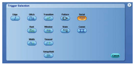
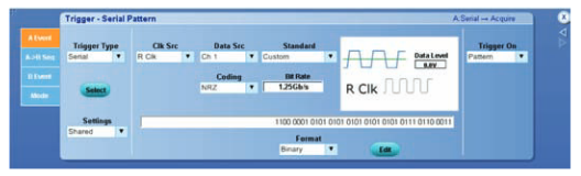
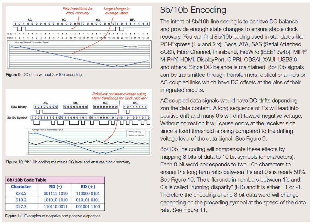
If you are looking for protocol errors, you would rather trigger on commands, characters, or bit sequences. Unfortunately a serial trigger circuit designed for NRZ patterns cannot find those faults because most high speed serial data signals are 8b/10b coded and require a dedicated hardware solution. See 8b/10b Encoding section below for details.
A standard NRZ trigger cannot trigger on words of 8b/10b coded data streams because of two reasons. First, the coding of the 8 bit word to 10b symbol will change at the speed of the data rate and would require an adjustment of the symbol rate in the trigger memory to the same speed.
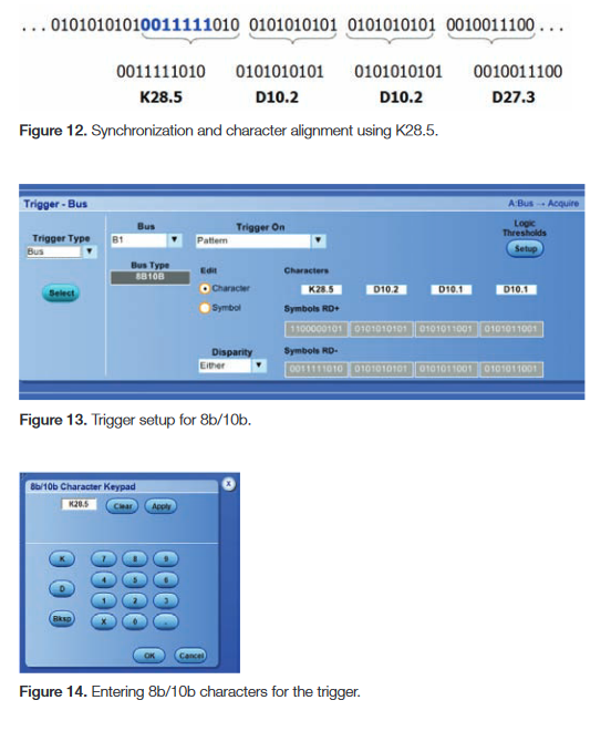
Second, triggering on the right 8b/10b symbol requires synchronization or alignment of the 8b/10b codes to the data stream. For real time triggering the hardware must be capable to synchronize to one of the "comma symbols" (K.28.1, K.28.5, and K.28.7) which are unique and can not be found in the data stream at any bit position in the code. The synchronization character can be somewhere in the data stream and might be very infrequent or appear only once. One example for a synchronization character is the comma symbol, K28.5 (011110101). Once the alignment symbol has been found, the decoding of the subsequent symbol values can proceed. See Figure 12.
Software "triggering" solutions actually perform a search through the acquired data and therefore have long dead times that cause very large gaps between the acquisitions and increase the chances of missing the character you are looking for.
Tektronix MSO/DPO/DSA70000 Series oscilloscopes are equipped with a dedicated trigger chip for triggering on 8b/10b data patterns in high speed serial signals up to 6.25 Gb/s. This ensures you will find even rare events.
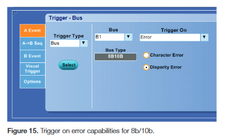
The 70000 Series oscilloscopes with 8b/10b serial bus triggering support several 8b/10b data values for triggering (see Figures 13 and 14).
First of all, the oscilloscope supports triggering on 8b/10b characters. Characters are acronyms for a pattern of 10 bits of the 8b/10b code, i.e. D31.6 or K28.5. A second option related to a high speed serial standard’s protocol is triggering on 8b/10b words (commands), where words consist of multiple characters (commonly 4 words or 40 bits). Every standard has its own word definitions.
A very unique feature and perhaps the most powerful debugging tool is the capability to trigger on 8b/10b code errors. No serial trigger would be able to trigger on all possible character errors, disparity errors or losses of byte synchronization, but Tektronix’ 8b/10b serial trigger allows you to trigger on common errors such as disparity or character errors.
Using 8b/10b Serial Pattern Triggering for Measuring Delay in Network Elements
In this section, we will show how Tektronix' 8b/10b serial pattern triggering can be used for measuring the time delay of an active network element. One might think this an easy task to solve even without special triggering on 8b/10b. But we will see it can be challenging if you have to measure the time delay under real conditions.
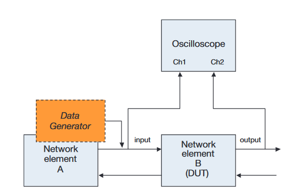
The setup for this measurement is shown in Figure 16. The input signal of the network element is connected to Channel 1 and the output data stream is connected to channel 2 of the oscilloscope. A data generator will provide the required data stream to the input of the network element (DUT). A unique pattern inside the data stream will perform as a timing reference. This timing reference needs to be a very rare pattern to prevent confusion with another timing position. If the pattern has been defined you can search for that pattern in the acquired signal of channel 1 and channel 2 and then measure the time between the two locations.
The 8b/10b decoding and search built into the Tektronix DPO/DSA/MSO70000 series oscilloscopes could help to find the sequence in the data stream. Because of its infrequent occurrence the search for the pattern can be very difficult. As we have discussed earlier in this application note, the acquisition memory of an oscilloscope is limited and will allow you to capture a very short time window only. Therefore the chance to find the pattern for the timing reference is very low. Unlike searching, the 8b/10b triggering of the 70000 Series oscilloscopes makes it very easy to find the sequence, because the triggering ensures that the pattern will always be inside of the acquisition window.
Without 8b/10b triggering the delay measurement would require a trigger signal from the data generator to the oscilloscope. That would be the only way to synchronize the starting point of the 8b/10b timing reference at the output of the data generator with the acquisition window of the oscilloscope.
However, this method will not work if you want to test an active network component under “real world” conditions. These conditions require a different setup as shown in Figure 16.
Here we have two network elements connected together with a bidirectional link. Network element A will act as a data source and is needed to ensure that network element B (DUT) will work in a desired operating mode. The communication link has to be established by proprietary commands and the data flow of this commands needs to be maintained during the measurements to keep the DUT in the desired operation mode. Therefore a static data pattern provided by any data generator will not work.
Similar to the previous example a unique pattern is required for a timing reference (marker) in the data stream. Since the pattern is very infrequent and there is no trigger signal available from the source network element A you will need the 8b/10b trigger to find the pattern in the input and the output signal of the DUT.
Finally the best way to see and measure the delay between the input and output of the network element is to use two zoom windows. The first zoom window will be placed at the beginning of the pattern sequence at channel 1 and the second zoom window at the beginning of the pattern sequence at channel 2. For the delay measurement you have to make sure that the acquisition time window of the oscilloscope is equal or greater than the delay time. With the help of the 8b/10b serial bus search function localisation of the two timing locations is very easy. The exact delay time can now be determined with two cursors or an automated measurement of the oscilloscope.
Summary
As more systems move from parallel bus architectures to serial buses, users need test equipment with unique serial bus features, such as triggering on and decoding of serial data. This application note focussed on 8b/10b coding which is widely used for high speed data links. Troubleshooting and verifying devices with 8b/10b serial buses can done using the Tektronix DPO/DSA/MSO70000 Series oscilloscopes with their powerful real time triggering of for 8b/10b serial buses.