Contactez-nous
Chat en direct avec un représentant Tek. Service disponible de 9 h à 17 h, CET jours ouvrables.
Appelez-nous au
Disponible de 9 h à 17 h CET jours ouvrables.
Télécharger
Télécharger des manuels, des fiches techniques, des logiciels, etc. :
Feedback
USB 2.0 Application Software
USB 2.0 Decoding, Triggering, and Compliance Testing Software
Les produits figurant sur cette fiche technique ne sont plus vendus par Tektronix.
Référez-vous à Tektronix Encore pour les équipements de test reconditionnés.
Consultez l'assistance et les informations de garantie pour ces produits.
Plus d’informations
- Logiciels d’analyse pour oscilloscopes
- Oscilloscope à signaux mixtes MSO/DPO2000B
- Oscilloscopes au phosphore numérique et à signaux mixtes MSO/DPO70000DX
- DPO7000
- Oscilloscope hautes performances DPO70000SX ATI
- MSO Série 5B
- Le MSO profil bas de Série 5
- Oscilloscope multidomaine de la série MDO3000
- Découvrez d'autres modèles Logiciel pour oscilloscopes, produits keithley, et RF
Lire en ligne :
These applications provide comprehensive, integrated tools for engineers designing USB-based embedded systems and validating the physical-layer compliance to the USB 2.0 standards. The applications are supported on the DPO/DSA/MSO70000C/D/DX/SX, DPO7000C, 5 and 6 Series MSO, MSO/DPO5000, MDO4000, and MDO3000 Series oscilloscopes.
Key features
- USB 2.0 Compliance Testing
- Automated Compliance Testing for USB 2.0 Verification
- Designed for use with MSO/DPO5000, DPO7000C, and DPO/DSA/MSO70000C/D/DX/SX Series Oscilloscopes
- SR-USB USB Triggering and Analysis
- Automated Trigger and Decode for USB 2.0 and 3.0
- Designed for use with MSO/DPO5000, DPO7000C, and DPO/DSA/MSO70000C/D/DX Series Oscilloscopes
- 5-SRUSB2 USB Triggering and Analysis
- Automated Trigger and Decode for USB 2.0
- Designed for use with 5 Series MSO
- DPO4USB USB 2.0 Triggering and Analysis
- Automated Trigger, Decode, and Search for USB 2.0
- Designed for use with MDO4000 Series Oscilloscopes
- MDO3USB USB 2.0 Triggering and Analysis
- Automated Trigger, Decode, and Search for USB 2.0
- Designed for use with MDO3000 Series Oscilloscopes
Applications
- Low-speed USB 2.0
- Full-speed USB 2.0
- High-speed USB 2.0
- SuperSpeed USB 3.0 (trigger and analysis)
Product description
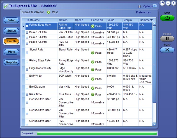
The Tektronix USB 2.0 compliance test application (Opt. USB2) and selected Tektronix oscilloscopes provide one-button compliance testing for USB 2.0 devices as specified by the USB-IF. The USB software automates the compliance testing and allows engineers to perform the required tests efficiently and reliably right on their bench.
The Tektronix MDO4000 Series oscilloscopes with the DPO4USB Serial Application Module, MDO3000 Series oscilloscopes with the MDO3USB Serial Application Module, 5 Series MSO with the 5-SRUSB2 application, and MSO/DPO5000, DPO7000C, and DPO/DSA/MSO70000C/D/DX Series oscilloscopes with the SR-USB application simplify analysis of USB 2.0 and 3.0 waveforms when validating and debugging USB-based embedded systems by providing trigger, decode, and search for low-speed, full-speed, high-speed, and SuperSpeed USB buses. MDO3USB offers automated decode and search for low-speed, full-speed, and high-speed USB buses, as well as triggering on low-speed and full-speed buses. DPO4USB offers automated trigger, decode, and search for low-speed, full-speed, and high-speed USB buses, enabling fast and efficient validation and debug.
USB2 – Automated USB 2.0 Physical Layer compliance testing
USB compliance testing has some unique measurement challenges:
- Designers must quickly and accurately perform all compliance tests recommended by the USB Implementers Forum, Inc. (USB-IF) before they can use the “certified” USB-IF logo on their packaging
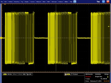
- Characterization of these electrical signals includes mask testing and parametric testing, for low-speed, full-speed, and high-speed hosts, devices, and hubs
- Signal speeds range from 1.5 Mb/s (low-speed) to 480 Mb/s (high-speed)
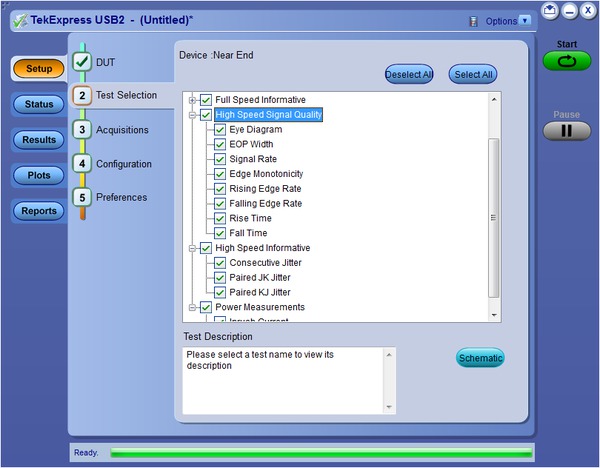
The USB2 application software provides automated compliance testing for USB 2.0 serial bus verification, including:
- Fully compliant with USB-IF tests for USB 2.0 compliance testing
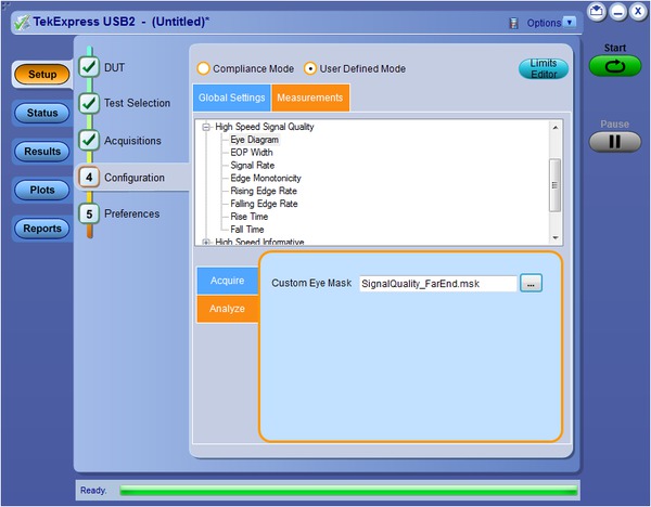
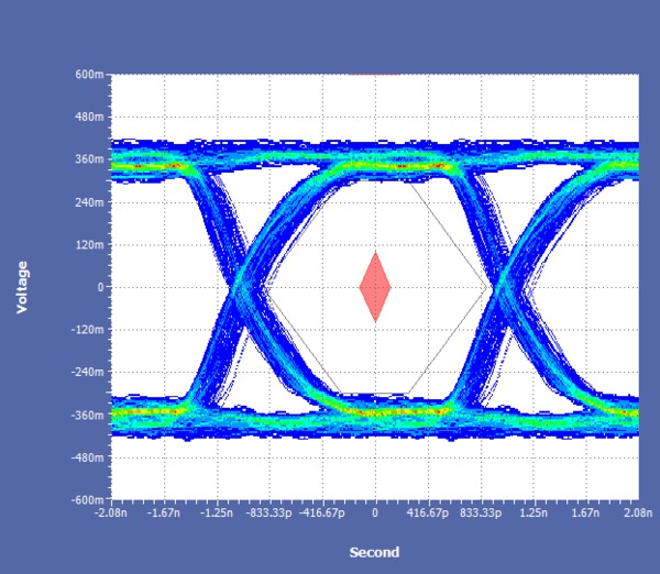
- Automated eye diagram analysis verifies signal quality against standard USB-IF eye masks or custom masks
- Automated oscilloscope setups for various tests eliminate time-consuming manual setups
- Comprehensive test fixture enables quick setup and signal access for a wide range of tests
- High-speed tests: Signal Quality, Receiver Sensitivity, Chirp, Reset, Reset from High Speed, Reset from Suspend, Resume, Suspend, Packet Parameter, and Monotonicity tests
- Automatic signal generator control for receiver sensitivity simplifies testing
- Online help fully documents test procedures
- User-configurable measurement limits for tolerance testing
- Supported on Windows 7 (64-bit) and Windows 10 (64-bit) operating systems
Quick Pass/Fail tests substantiated with results make the USB2 application the preferred solution for USB 2.0 physical-layer validation. In-depth analysis is possible with the statistical information about the tests performed. The user-defined measurement limits and custom mask testing also help to perform tolerance testing on a design.
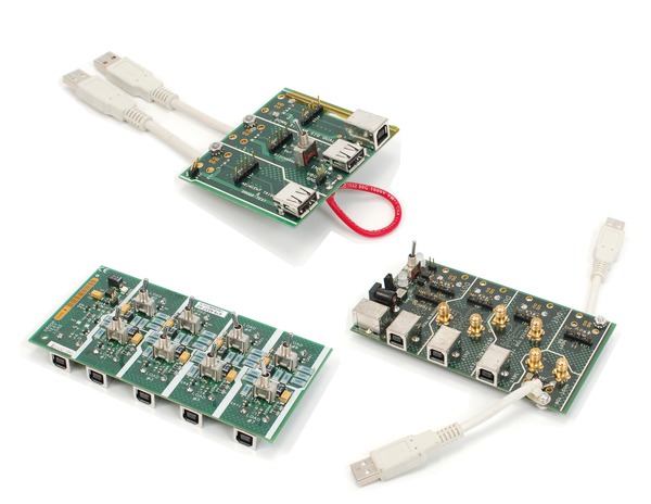
USB2 compliance test fixtures
The Tektronix TDSUSBF test fixture set provides a probing solution for the Low- and Full-speed Signal Quality, Inrush Current, Drop and Droop, Receiver Sensitivity, and Impedance Measurement test. The TDSUSBF test fixture set is ordered separately.
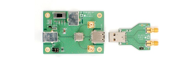
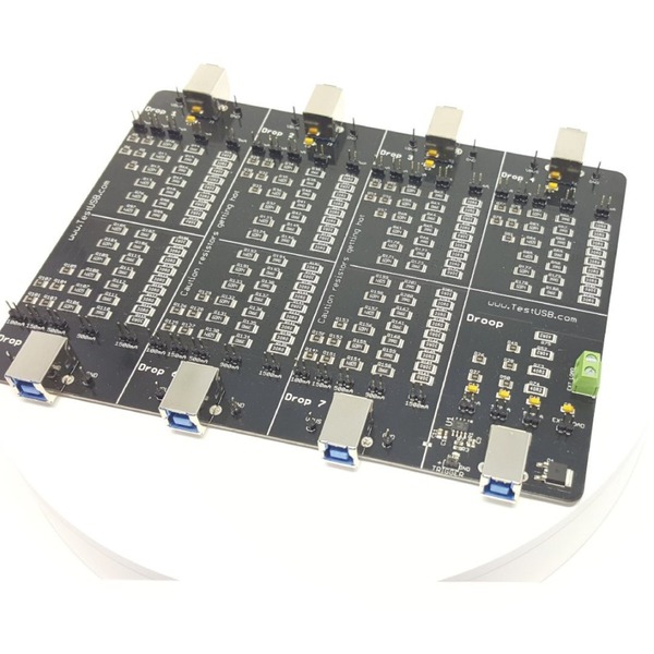
The High-speed signal quality fixture set (USB2SIGQUAL) provides the necessary SMA-based connection for performing Eye Diagram and other signal quality measurements. The USB 2.0 / 3.0 Drop-Droop fixture (USB2/3_DD) from www.fixturesolutions.com provides sufficient loads for testing voltage drop and droop levels while testing Host or Hubs (downstream ports supplying VBUS).
SR-USB USB 2.0 and 3.0 triggering and analysis
Debugging USB-based embedded systems designs provides some complex measurement and analysis challenges:
- Capturing specific USB addresses and data
- Displaying the elements of the USB message in an understandable format, in a variety of formats, for a wide variety of engineers and technicians
- Time-correlating USB messages with analog and digital signals in the embedded system
- Capture long time windows of USB traffic and then find specific events within the acquired data
The optional SR-USB application software, installed in an MSO/DPO5000, DPO7000C, or DPO/DSA/MSO70000C/D/DX Series oscilloscope, provides a robust set of tools for debugging embedded systems with USB 2.0 and 3.0 serial buses, including:
- Automated serial triggering and decode for low-speed, full-speed, and high-speed USB 2.0 signals
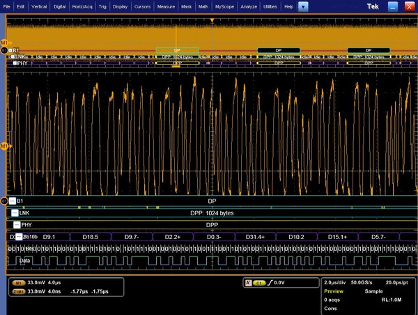
- Serial triggering and decode for SuperSpeed USB 3.0 signals (8b/10b)
- Trigger on all the critical elements of a USB bus such as address, data, etc.
- Decode all the critical elements of each USB message. No more counting 1s and 0s!
- Search through long acquisitions using user-defined criteria to find specific messages
- Event table shows decoded serial bus activity in a tabular, time-stamped format for quick summary of system activity
USB serial triggering
Trigger on packet content such as sync, reset, suspend/resume, token (address) packets with specific address and endpoint, specific data content, handshake packets, special packets, and errors.

USB serial decode
The SR-USB application provides a higher-level, combined view of the individual signals that make up the USB bus, making it easy to identify where packets begin and end and identify subpacket components such as sync, PID, data, CRC, errors, etc.
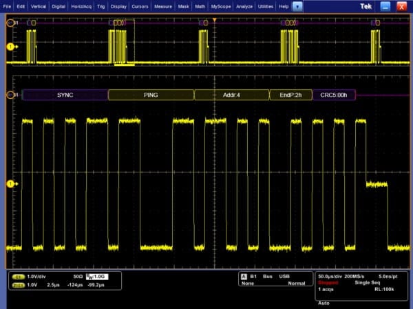
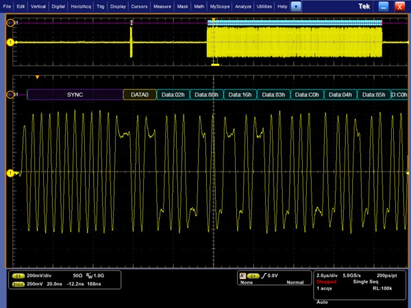
Are you wasting time manually decoding the waveform? Tired of having to visually inspect the waveform to count clocks, determine if each bit is a 1 or a 0, combine bits into bytes, and determine the hex value? Let the oscilloscope with the SR-USB application do it for you! Once you've set up a USB bus, the MSO/DPO5000, DPO7000C, or DPO/DSA/MSO70000C/D/DX Series will decode each packet on the bus, and display the value in Hex, Binary, or ASCII in the bus waveform.
USB 2.0 Event table
In addition to seeing decoded packet data on the bus waveform itself, you can view all captured packets in a tabular view much like you would see in a software listing. Packets are time stamped and listed consecutively with columns for each component (Time, PID, Address, Payload, and Errors).

USB 2.0 search
USB packet content triggering is very useful for isolating the event of interest, but once you’ve captured it and need to analyze the surrounding data, what do you do? In the past, users had to manually scroll through the waveform counting and converting bits and looking for what caused the event. With the SR-USB application installed, you can enable the oscilloscope to automatically search through the acquired data for user-defined criteria including serial packet content. Each occurrence is highlighted by a search mark. Rapid navigation between marks is as simple as pressing the Previous (←) and Next (→) buttons on the oscilloscope front panel.
5-SRUSB2 USB 2.0 triggering and analysis
Debugging USB-based embedded systems designs provides some complex measurement and analysis challenges:
- Capturing specific USB addresses and data
- Displaying the elements of the USB message in an understandable format, in a variety of formats, for a wide variety of engineers and technicians
- Time-correlating USB messages with analog and digital signals in the embedded system
- Capture long time windows of USB traffic and then find specific events within the acquired data
The optional 5-SRUSB2 application software, installed in a 5 Series MSO, provides a robust set of tools for debugging embedded systems with USB 2.0 serial buses, including:
- Automated serial triggering and decode for low-speed, full-speed, and high-speed USB 2.0 signals
- Trigger on all the critical elements of a USB bus such as address, data, etc.
- Decode all the critical elements of each USB message. No more counting 1s and 0s!
- Search through long acquisitions using user-defined criteria to find specific messages
- Results table shows decoded serial bus activity in a tabular, time-stamped format for quick summary of system activity
USB serial triggering
Trigger on packet content such as sync, reset, suspend/resume, token (address) packets with specific address and endpoint, specific data content, handshake packets, special packets, and errors.

USB 2.0 serial decode
The 5-SRUSB2 application provides a higher-level, combined view of the individual signals that make up the USB bus, making it easy to identify where packets begin and end and identify sub-packet components such as sync, PID, data, CRC, errors, etc.
Tired of manually decoding the waveform? Let the oscilloscope with the 5-SRUSB2 application do it for you! Once you've set up a USB bus, the 5 Series MSO will decode each packet on the bus, and display the value in Hex, Binary, or ASCII in the bus waveform.
USB 2.0 Results Table
In addition to seeing decoded packet data on the bus waveform itself, you can view all captured packets in a tabular view much like you would see in a software listing. Packets are time stamped and listed consecutively with columns for each component (Time, PID, Address, Payload, and Errors).

USB 2.0 search
USB packet content triggering is very useful for isolating the event of interest, but once you’ve captured it and need to analyze the surrounding data, what do you do? In the past, users had to manually scroll through the waveform counting and converting bits and looking for what caused the event. With the 5-SRUSB2 application installed, you can enable the oscilloscope to automatically search through the acquired data for user- defined criteria including serial packet content. Each occurrence is highlighted by a search mark. Rapid navigation between marks is as simple as pressing the
Previous (←) and
Next (→) buttons on the oscilloscope front panel.

DPO4USB/MDO3USB - USB 2.0 triggering and analysis
Debugging USB-based embedded system designs provides some complex measurement and analysis challenges:
- Capturing specific USB addresses and data
- Displaying the elements of the USB message in an understandable format, in a variety of formats, for a wide variety of engineers and technicians
- Time-correlating USB messages with analog and digital signals in the embedded system
- Capture long time windows of USB traffic and then find specific events within the acquired data
The optional DPO4USB application module, installed in an MDO4000 Series oscilloscope, or the optional MDO3USB application module, installed in an MDO3000 Series oscilloscope, provides a robust set of tools for debugging embedded systems with USB 2.0 serial buses, including:
- Automated serial triggering for low-speed, full-speed, and high-speed (DPO4USB only) USB 2.0 signals
- Automated serial decode and search for low-speed, full-speed, and high-speed USB 2.0 signals
- Trigger on all the critical elements of a USB bus such as address, data, etc.
- Decode all the critical elements of each USB message. No more counting 1s and 0s!
- Search through long acquisitions using user-defined criteria to find specific messages
- Event table shows decoded serial bus activity in a tabular, time-stamped format for quick summary of system activity
USB 2.0 serial triggering
Trigger on packet content such as sync, reset, suspend/resume, token (address) packets with specific address and endpoint, specific data content, handshake packets, special packets, and errors.
USB 2.0 decode
The DPO4USB/MDO3USB USB Serial Application Module provides a higher-level, combined view of the individual signals that make up the USB bus, making it easy to identify where packets begin and end and identifying subpacket components such as sync, PID, data, CRC, errors, etc.


Are you wasting time manually decoding the waveform? Tired of having to visually inspect the waveform to count clocks, determine if each bit is a 1 or a 0, combine bits into bytes, and determine the hex value? Let the oscilloscope with a USB Triggering and Analysis Application module do it for you! Once you've set up a USB bus, the MDO4000 or MDO3000 Series will decode each packet on the bus, and display the value in Hex, Binary, or ASCII in the bus waveform.
USB 2.0 Event table
In addition to seeing decoded packet data on the bus waveform itself, you can view all captured packets in a tabular view much like you would see in a software listing. Packets are time stamped and listed consecutively with columns for each component (Time, PID, Address, Payload, and Errors).

USB 2.0 search
USB packet content triggering is very useful for isolating the event of interest, but once you've captured it and need to analyze the surrounding data, what do you do? In the past, users had to manually scroll through the waveform counting and converting bits and looking for what caused the event. With a USB Serial Application Module, you can enable the oscilloscope to automatically search through the acquired data for user-defined criteria including serial packet content. Each occurrence is highlighted by a search mark. Rapid navigation between marks is as simple as pressing the Previous (←) and Next (→) buttons on the oscilloscope front panel. Search results can also be displayed in a time-stamped Search Mark Table and the search results can be exported to a .CSV file.
Specifications
USB2
- Instrument compatibility
Oscilloscope Description MSO5034/B
DPO5034/B
MSO5054/B
DPO5054/B
MSO5104/B
DPO5104/B
DPO7054C
DPO7104C
USB 2.0 Compliance: Low-speed and Full-speed USB MSO5204/B
DPO5204/B
DPO7254C
DPO7354C
All DPO/DSA/MSO70000C/D/DX/SX models
USB 2.0 Compliance: Low-speed, Full-speed, and High-speed USB
Testing options
- USB tests
- Host, Hub, and Device
- Signal Quality tests
- Eye Diagram Test, Jitter (JK, KJ, and Consecutive), Crossover Voltage Range, Signal Rate, End-of-Packet Width, Rising Edge Rate, and Falling Edge Rate
- High-speed tests
- Receiver Sensitivity, Chirp, Reset, Resume, Reset from High Speed, Reset from Suspend, Packet Parameter, and Edge Monotonicity
- Inrush Current check
- Data-sufficiency readout. Coulombs and Capacitance listed across inrush regions
- Droop test
- Volts readout
- Speed selection
- Low-speed (LS), Full-speed (FS), and High-speed (HS)
- Signal direction
- Upstream and Downstream
- Test Point selection
- Near End and Far End
- Report Generation format
- MHTML, PDF, and CSV formats
SR-USB
- Instrument compatibility
Oscilloscope Description MSO5034/B
DPO5034/B
MSO5054/B
DPO5054/B
DPO7054C
Trigger and Decode: Low-speed and Full-speed USB MSO5104/B
DPO5104/B
MSO5204/B
DPO5204/B
Trigger and Decode: Low-speed, Full-speed, and High-speed USB DPO7104C
DPO7254C
DPO7354C
Decode: Low-speed, Full-speed, and High-speed USB Trigger: Low-speed and Full-speed USB
All DPO/DSA/MSO70000C/D/DX models
Decode: Low-speed, Full-speed, and High-speed, and SuperSpeed (8b/10b) USB
Trigger: Low-speed and Full-speed USB
Bus Setup options
- USB compatibility
- Low-speed and Full-speed: All MSO/DPO5000, DPO7000C, and DPO/DSA/MSO70000C/D/DX Series models
High-speed: MSO/DPO5204/B, MSO/DPO5104/B, DPO7354C, DPO7254C, DPO7104C, and DPO/DSA/MSO70000C/D/DX models only
SuperSpeed: DPO/DSA/MSO70000C/D/DX models only
- Sources
- Single-ended
- Analog channels 1-4
Math channels 1-4
Digital channels D0-D15 (MSO5000 and MSO70000C/DX Series only)
- Differential
- Analog channels 1-4
Math channels 1-4
- Recommended probing
- Low-speed and Full-speed: Single-ended or differential
High-speed/SuperSpeed: Differential
- Address/Data formats available
- Hex, Binary, Decimal
Decimal: Frame and Address
Hex or ASCII: Data
- Display modes
- Bus
- Bus only
- Bus and waveforms
- Simultaneous display of bus and digital waveforms
- Event table
- Decoded packet data in a tabular view
Bus Trigger options
- Trigger and/or search on
- Low-speed
- Trigger/Search on Sync, Reset, Suspend, Resume, End of Packet, Token (Address) Packet, Data Packet, Handshake Packet, Special Packet, Error
Packet type Description Token packet Any token type, SOF, OUT, IN, SETUP; Address can be further specified to trigger on ≤, <, =, >, ≥, ≠ a particular value, or inside or outside of a range. Frame number can be specified for SOF token using Binary, Hex, Unsigned Decimal, and Don't Care digits. Data packet Any data type, DATA0, DATA1; Data can be further specified to trigger on ≤, <, =, >, ≥, ≠ a particular data value, or inside or outside of a range Handshake packet Any handshake type, ACK, NAK, STALL Special packet Any special type, Reserved Error PID Check, CRC5, CRC16, Bit Stuffing - Full-speed
- Trigger/Search on Sync, Reset, Suspend, Resume, End of Packet, Token (Address) Packet, Data Packet, Handshake Packet, Special Packet, Error
Packet type Description Token packet Any token type, SOF, OUT, IN, SETUP; Address can be further specified to trigger on ≤, <, =, >, ≥, ≠ a particular value, or inside or outside of a range. Frame number can be specified for SOF token using Binary, Hex, Unsigned Decimal, and Don't Care digits. Data packet Any data type, DATA0, DATA1; Data can be further specified to trigger on ≤, <, =, >, ≥, ≠ a particular data value, or inside or outside of a range Handshake packet Any handshake type, ACK, NAK, STALL Special packet Any special type, PRE, Reserved. Error PID Check, CRC5, CRC16, Bit Stuffing - High-speed
- Trigger/Search on Sync, Reset, Suspend, Resume, End of Packet, Token (Address) Packet, Data Packet, Handshake Packet, Special Packet, Error
Packet type Description Token packet Any token type, SOF, OUT, IN, SETUP; Address can be further specified to trigger on ≤, <, =, >, ≥, ≠ a particular value, or inside or outside of a range. Frame number can be specified for SOF token using Binary, Hex, Unsigned Decimal, and Don't Care digits. Data packet Any data type, DATA0, DATA1, DATA2, MDATA; Data can be further specified to trigger on ≤, <, =, >, ≥, ≠ a particular data value, or inside or outside of a range. Handshake packet Any handshake type, ACK, NAK, STALL, NYET Special packet Any special type, ERR, SPLIT, PING, Reserved. SPLIT packet components that can be specified include: Hub Address
Start/Complete – Don't Care, Start (SSPLIT), Complete (CSPLIT)
Port Address
Start and End bits – Don't Care, Control/Bulk/Interrupt (Full-speed Device, Low-speed Device), Isochronous (Data is Middle, Data is End, Data is Start, Data is All)
Endpoint Type – Don't Care, Control, Isochronous, Bulk, Interrupt
Error PID Check, CRC5, CRC16, Any - SuperSpeed
- Trigger/Search on Ordered Set, Character, Symbol, Error
Packet type Description Ordered Set SKP, DPPSTART, DPPEND, DPPABORT Character K28.1 (SKP), K28.5 (COM) or other user-defined (8b/10b) Symbol User-defined with positive, negative, or either disparity Error Character or Disparity
Bus decode
- USB Data rates
- Low-speed: 1.5 Mb/s
Full-speed: 12 Mb/s
High-speed: 480 Mb/s
SuperSpeed: 5 Gb/s
- Decode display
- Start (green bar)
PID (yellow packet)
Data (cyan packet)
CRC (purple packet)
Stop (red bar)
5-SRUSB2
- Instrument compatibility
Oscilloscope Description MSO54 opt. 5-BW-350
MSO54 opt. 5-BW-500
MSO56 opt. 5-BW-350
MSO56 opt. 5-BW-500
MSO58 opt. 5-BW-350
MSO58 opt. 5-BW-500
Trigger and Decode: Low-speed and Full-speed USB MSO54 opt. 5-BW-1000
MSO54 opt. 5-BW-2000
MSO56 opt. 5-BW-1000
MSO56 opt. 5-BW-2000
MSO58 opt. 5-BW-1000
MSO58 opt. 5-BW-2000
Trigger and Decode: Low-speed, Full-speed, and High-speed USB
Bus Setup options
- USB compatibility
- Low-speed and Full-speed: All 5 Series MSO models with 350 MHz or 500 MHz bandwidth
High-speed: All 5 Series MSO models with 1 GHz or 2 GHz bandwidth
- Sources
- Single-ended
- Analog channels
Digital channels
Active Math channels
Active Reference waveforms
- Differential
- Analog channels
Active Math channels
Active Reference waveforms
- Recommended probing
- Low-speed and Full-speed: Single-ended or differential
High-speed: Differential
- Address/Data formats available
- Hex, Binary, Decimal
Decimal: Frame and Address
Hex or ASCII: Data
- Display modes
- Bus
- Bus only
- Bus and waveforms
- Simultaneous display of bus and digital waveforms
- Results table
- Decoded packet data in a tabular view
Bus Trigger options
- Trigger and/or search on
- Low-speed
- Trigger/Search on Sync, Handshake Packet, Special Packet, Error. Token (Address) Packet, Data Packet, Reset, Suspend, Resume, End of Packet.
Packet type Description Token packet Any token type, SOF, OUT, IN, SETUP; Address can be further specified to trigger on ≤, <, =, >, ≥, ≠ a particular value, or inside or outside of a range. Frame number can be specified for SOF token using Binary, Hex, Unsigned Decimal, and Don't Care digits. Data packet Any data type, DATA0, DATA1; 1 – 16 bytes of Data can be further specified to trigger on ≤, <, =, >, ≥, ≠ a particular data value, or inside or outside of a range. Handshake packet Any handshake type, ACK, NAK, STALL Special packet Any special type, PRE, Reserved Error PID Check bits, Token CRC5, Data CRC16, Bit Stuffing - Full-speed
- Trigger/Search on Sync, Handshake Packet, Special Packet, Error, Token (Address) Packet, Data Packet, Reset, Suspend, Resume, End of Packet
Packet type Description Token packet Any token type, SOF, OUT, IN, SETUP; Address can be further specified to trigger on ≤, <, =, >, ≥, ≠ a particular value, or inside or outside of a range. Frame number can be specified for SOF token using Binary, Hex, Unsigned Decimal, and Don't Care digits. Data packet Any data type, DATA0, DATA1; 1 – 16 bytes of Data can be further specified to trigger on ≤, <, =, >, ≥, ≠ a particular data value, or inside or outside of a range. Handshake packet Any handshake type, ACK, NAK, STALL Special packet Any special type, PRE, Reserved. Error PID Check bits, Token CRC5, Data CRC16, Bit Stuffing - High-speed
- Trigger/Search on Sync, Handshake Packet, Special Packet, Error, Token (Address) Packet, Data Packet, Reset, Suspend, Resume, End of Packet
Packet type Description Token packet Any token type, SOF, OUT, IN, SETUP; Address can be further specified to trigger on ≤, <, =, >, ≥, ≠ a particular value, or inside or outside of a range. Frame number can be specified for SOF token using Binary, Hex, Unsigned Decimal, and Don't Care digits. Data packet Any data type, DATA0, DATA1, DATA2, MDATA; 1 – 16 bytes of Data can be further specified to trigger on ≤, <, =, >, ≥, ≠ a particular data value, or inside or outside of a range. Handshake packet Any handshake type, ACK, NAK, STALL, NYET Special packet Any special type, ERR, SPLIT, PING, Reserved. SPLIT packet components that can be specified include:
Hub Address
Start/Complete – Don't Care, Start (SSPLIT), Complete (CSPLIT)
Port Address
Start and End bits – Don't Care, Control/Bulk/Interrupt (Full-speed Device, Low-speed Device), Isochronous (Data is Middle, Data is End, Data is Start, Data is All)
Endpoint Type – Don't Care, Control, Isochronous, Bulk, Interrupt
Error PID Check, CRC5, CRC16, Any - Decode display
- Start (green bar)
PID (yellow packet)
Data (cyan packet)
CRC (purple packet)
Stop (red bar)
DPO4USB
- Instrument compatibility
Oscilloscope Description All 100 MHz, 200 MHz, 350 MHz, 500 MHz MDO4000/B, MSO4000/B, and DPO40001/B/C Series Trigger and Decode: Low-speed and Full-speed MSO4104
DPO41041
Trigger: Low-speed and Full-speed
Decode: Low-speed, Full-speed, and High-speed
All 1 GHz models of MSO/DPO4000B and MDO4000/B/C Series Trigger and Decode: Low Speed, Full Speed, and High Speed
Bus Setup options
- USB 2.0 compatibility
- Low-speed and Full-speed: All MDO/MSO/DPO4000 Series models
High-speed: Models with 1 GHz analog channel bandwidth
- Sources
- Single-ended
- Analog channels 1-4
Digital channels D0-D15 (MDO and MSO Series only)
- Differential
- Analog channels 1-4
Math channel
Reference channels 1-4
- Recommended probing
- Low-speed and Full-speed: Single-ended or differential
High-speed: Differential
- Threshold presets
- Low-speed and Full-speed: Single-ended (D+: 1.4 V; D-: -1.4 V), Differential (High: 1.4 V; Low: -1.4 V)
High-speed: Differential (High: 100 mV; Low: -100 mV)
- Address/Data formats available
- Hex, Binary, Decimal
Decimal: Frame and Address
Hex or ASCII: Data
- Display modes
- Bus
- Bus only
- Bus and waveforms
- Simultaneous display of bus and digital waveforms
- Event table
- Decoded packet data in a tabular view
Bus Trigger options
- Trigger and/or search on
- Low-speed
- Trigger/Search on Sync, Reset, Suspend, Resume, End of Packet, Token (Address) Packet, Data Packet, Handshake Packet, Special Packet, Error
Packet type Description Token packet Any token type, SOF, OUT, IN, SETUP; Address can be further specified to trigger on ≤, <, =, >, ≥, ≠ a particular value, or inside or outside of a range. Frame number can be specified for SOF token using Binary, Hex, Unsigned Decimal, and Don't Care digits. Data packet Any data type, DATA0, DATA1; Data can be further specified to trigger on ≤, <, =, >, ≥, ≠ a particular data value, or inside or outside of a range. Handshake packet Any handshake type, ACK, NAK, STALL Special packet Any special type, Reserved Error PID Check, CRC5, CRC16, Bit Stuffing - Full-speed
- Trigger/Search on Sync, Reset, Suspend, Resume, End of Packet, Token (Address) Packet, Data Packet, Handshake Packet, Special Packet, Error
Packet type Description Token packet Any token type, SOF, OUT, IN, SETUP; Address can be further specified to trigger on ≤, <, =, >, ≥, ≠ a particular value, or inside or outside of a range. Frame number can be specified for SOF token using Binary, Hex, Unsigned Decimal, and Don't Care digits. Data packet Any data type, DATA0, DATA1; Data can be further specified to trigger on ≤, <, =, >, ≥, ≠ a particular data value, or inside or outside of a range. Handshake packet Any handshake type, ACK, NAK, STALL Special packet Any special type, PRE, Reserved. Error PID Check, CRC5, CRC16, Bit Stuffing - High-speed
- Trigger/Search on Sync, Reset, Suspend, Resume, End of Packet, Token (Address) Packet, Data Packet, Handshake Packet, Special Packet, Error
Packet type Description Token packet Any token type, SOF, OUT, IN, SETUP; Address can be further specified to trigger on ≤, <, =, >, ≥, ≠ a particular value, or inside or outside of a range. Frame number can be specified for SOF token using Binary, Hex, Unsigned Decimal, and Don't Care digits. Data packet Any data type, DATA0, DATA1, DATA2, MDATA; Data can be further specified to trigger on ≤, <, =, >, ≥, ≠ a particular data value, or inside or outside of a range. Handshake packet Any handshake type, ACK, NAK, STALL, NYET Special packet Any special type, ERR, SPLIT, PING, Reserved. SPLIT packet components that can be specified include: Hub Address
Start/Complete – Don't Care, Start (SSPLIT), Complete (CSPLIT)
Port Address
Start and End bits – Don't Care, Control/Bulk/Interrupt (Full-speed Device, Low-speed Device), Isochronous (Data is Middle, Data is End, Data is Start, Data is All)
Endpoint Type – Don't Care, Control, Isochronous, Bulk, Interrupt
Error PID Check, CRC5, CRC16
Bus decode
- USB Data rates
- Low-speed: 1.5 Mb/s
Full-speed: 12 Mb/s
High-speed: 480 Mb/s
- Decode display
- Start (green bar)
PID (yellow packet)
Data (cyan packet)
CRC (purple packet)
Stop (red bar)
MDO3USB
- Instrument compatibility
Oscilloscope Description All 100 MHz, 200 MHz, 350 MHz, 500 MHz MDO3000 Series Trigger and Decode: Low-speed and Full-speed All 1 GHz MDO3000 Series Trigger: Low-speed and Full-speed
Decode: Low-speed, Full-speed, and High-speed
Bus Setup options
- USB 2.0 compatibility
- Low-speed and Full-speed: All MDO3000 Series models
High-speed: Models with 1 GHz analog channel bandwidth
- Sources
- Single-ended
- Analog channels 1-4
Digital channels D0-D15 (models with MSO options only)
- Differential
- Analog channels 1-4
Math channel
Reference channels 1-4
- Recommended probing
- Low-speed and Full-speed: Single-ended or differential
High-speed: Differential
- Threshold presets
- Low-speed and Full-speed: Single-ended (D+: 1.4 V; D-: -1.4 V), Differential (High: 1.4 V; Low: -1.4 V)
High-speed: Differential (High: 100 mV; Low: -100 mV)
- Address/Data formats available
- Hex, Binary, Decimal
Decimal: Frame and Address
Hex or ASCII: Data
- Display modes
- Bus
- Bus only
- Bus and waveforms
- Simultaneous display of bus and digital waveforms
- Event table
- Decoded packet data in a tabular view
Bus Trigger options
- Trigger and/or search on
- Low-speed
- Trigger/Search on Sync, Reset, Suspend, Resume, End of Packet, Token (Address) Packet, Data Packet, Handshake Packet, Special Packet, Error
Packet type Description Token packet Any token type, SOF, OUT, IN, SETUP; Address can be further specified to trigger on ≤, <, =, >, ≥, ≠ a particular value, or inside or outside of a range. Frame number can be specified for SOF token using Binary, Hex, Unsigned Decimal, and Don't Care digits. Data packet Any data type, DATA0, DATA1; Data can be further specified to trigger on ≤, <, =, >, ≥, ≠ a particular data value, or inside or outside of a range. Handshake packet Any handshake type, ACK, NAK, STALL Special packet Any special type, Reserved Error PID Check, CRC5, CRC16, Bit Stuffing - Full-speed
- Trigger/Search on Sync, Reset, Suspend, Resume, End of Packet, Token (Address) Packet, Data Packet, Handshake Packet, Special Packet, Error
Packet type Description Token packet Any token type, SOF, OUT, IN, SETUP; Address can be further specified to trigger on ≤, <, =, >, ≥, ≠ a particular value, or inside or outside of a range. Frame number can be specified for SOF token using Binary, Hex, Unsigned Decimal, and Don't Care digits. Data packet Any data type, DATA0, DATA1; Data can be further specified to trigger on ≤, <, =, >, ≥, ≠ a particular data value, or inside or outside of a range. Handshake packet Any handshake type, ACK, NAK, STALL Special packet Any special type, PRE, Reserved. Error PID Check, CRC5, CRC16, Bit Stuffing - High-speed
- Trigger/Search on Sync, Reset, Suspend, Resume, End of Packet, Token (Address) Packet, Data Packet, Handshake Packet, Special Packet, Error
Packet type Description Token packet Any token type, SOF, OUT, IN, SETUP; Address can be further specified to trigger on ≤, <, =, >, ≥, ≠ a particular value, or inside or outside of a range. Frame number can be specified for SOF token using Binary, Hex, Unsigned Decimal, and Don't Care digits. Data packet Any data type, DATA0, DATA1, DATA2, MDATA; Data can be further specified to trigger on ≤, <, =, >, ≥, ≠ a particular data value, or inside or outside of a range. Handshake packet Any handshake type, ACK, NAK, STALL, NYET Special packet Any special type, ERR, SPLIT, PING, Reserved. SPLIT packet components that can be specified include: Hub Address
Start/Complete – Don't Care, Start (SSPLIT), Complete (CSPLIT)
Port Address
Start and End bits – Don't Care, Control/Bulk/Interrupt (Full-speed Device, Low-speed Device), Isochronous (Data is Middle, Data is End, Data is Start, Data is All)
Endpoint Type – Don't Care, Control, Isochronous, Bulk, Interrupt
Error PID Check, CRC5, CRC16
Bus decode
- USB Data rates
- Low-speed: 1.5 Mb/s
Full-speed: 12 Mb/s
High-speed: 480 Mb/s
- Decode display
- Start (green bar)
PID (yellow packet)
Data (cyan packet)
CRC (purple packet)
Stop (red bar)
1For DPO4000 (non-B) Series products with serial numbers lower than C020000 and no serial triggering hardware update installed, USB triggering is not supported.
Ordering information
USB2
| Model | New instrument orders | Product upgrades | Floating licenses |
|---|---|---|---|
| MSO/DPO5000 Series | Opt. USB2 | DPO-UP, Opt. USB2 | DPOFL-USB2 |
| DPO7000C Series | Opt. USB2 | DPO-UP, Opt. USB2 | DPOFL-USB2 |
| DPO/DSA/MSO70000C/D/DX/SX Series | Opt. USB2 | DPO-UP, Opt. USB2 | DPOFL-USB2 |
SR-USB
| Model | New instrument orders | Product upgrades | Floating licenses |
|---|---|---|---|
| MSO/DPO5000 Series | Opt. SR-USB | DPO-UP Opt. SR-USB | DPOFL-SR-USB |
| DPO7000C Series | Opt. SR-USB | DPO-UP Opt. SR-USB | DPOFL-SR-USB |
| DPO/DSA/MSO70000C/D/DX Series | Opt. SR-USB | DPO-UP Opt. SR-USB | DPOFL-SR-USB |
5-SRUSB2
| Model | New instrument orders | Product upgrades | Floating licenses |
|---|---|---|---|
| 5 Series MSO | Opt. 5-SRUSB2 | SUP5-SRUSB2 | - |
DPO4USB
| Model | New instrument orders | Product upgrades | Floating licenses |
|---|---|---|---|
| MDO4000 Series | DPO4USB | DPO4USB | - |
MDO3USB
| Model | New instrument orders | Product upgrades | Floating licenses |
|---|---|---|---|
| MDO3000 Series | MDO3USB | MDO3USB | - |
Recommended accessories
The P6248, P6330, TDP1500, and TDP3500 differential probes and P6245, TAP1500, and TAP2500 single-ended probes are approved for compliance testing.
Higher-performance active or differential probes may be used for design applications. It is recommended to use a probe with 1X attenuation for best results.
Please refer to www.tektronix.com/probes for further information on the recommended models of probes and any necessary probe adapters.
Accessories
- TDSUSBF
- USB 2.0 test fixture set
- AWG5202 or AWG5204 or AWG5208 or AWG5000C or AWG7000C or AWG70000A series
- Arbitrary waveform generator, signal source for receiver sensitivity tests. 5X attenuators are required
- USB2SIGQUAL
- High-speed Signal Quality test fixture (sold through Allion, go to: https://www.allion.com/test-fixture/usb-tf-hs-device-and-host/)
- USB2/3_DD
- Droop-Drop fixture (sold through www.fixturesolutions.com)
SR-USB
Refer to www.tektronix.com/probes for further information on the recommended probes and any necessary probe adapters.
5-SRUSB2
Refer to www.tektronix.com/probes for further information on the recommended probes and any necessary probe adapters.
DPO4USB
Refer to www.tektronix.com/probes for further information on the recommended probes and any necessary probe adapters.
MDO3USB
Refer to www.tektronix.com/probes for further information on the recommended probes and any necessary probe adapters.
Additional information
Tektronix offers a range of solutions for USB testing, including HSIC (High Speed Inter Connect) and USB 3.1. To see a comprehensive listing, and download the latest resources, visit www.tektronix.com/USB.
USB solution updates and up-to-date instrument software upgrades are available at www.tektronix.com/downloads.

Tektronix is registered to ISO 9001 and ISO 14001 by SRI Quality System Registrar. 61W-26136-13

