Contactez-nous
Chat en direct avec un représentant Tek. Service disponible de 9 h à 17 h, CET jours ouvrables.
Téléphone
Appelez-nous au
Disponible de 9 h à 17 h CET jours ouvrables.
Télécharger
Télécharger des manuels, des fiches techniques, des logiciels, etc. :
Feedback
EMI Measurement System with EMC120 Windows Software
27120B

Features & Benefits
EMC Diagnostic Work
- EMC Prequalification Testing Configurable System Designed to Meet Your EMI Testing Needs
- Powerful EMC120 Software Saves Time in Acquiring Data and Preparing Engineering Reports
- Built-In 2712 Preamp Provides Low-Noise Floor for Tight Spec Limits
- Diagnose and Correct "Hot Spots" Using the 2712 and Near-Field Probes
- Option 11 Includes Antennas, Tripod, and Cable for Radiated Emissions Measurements
- Option 16 Includes LISN and Transient Limiter for Conducted Emissions Measurements
- Option 17 Provides 2706 RF Preselector Which Protects Against Signal Overload
Applications
- EMC Diagnostic Work
- EMC Prequalification Testing
Maximize the probability that your product will be certified the first time through the EMC test lab. Minimize costly delays resulting from retesting your products. Ensure continued compliance throughout your product's life cycle.
The time to address compliance is before it becomes a problem. Proper attention to EMC, from the design stage through precertification testing, can reduce your product development cost and decrease your time to market.
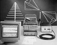
Achieve these objectives and more with the Tektronix 27120B EMI Measurement System - a complete solution for EMI pre- and post-certification of your products. The heart of the system is the easy-to-use 2712 Option 12 Spectrum Analyzer. It includes many features helpful in identifying and measuring EMC signals:
- Internal preamp
- Frequency counter
- AM/FM demodulator
- True analog display
- 4-trace digital display
- Peak, Quasi-peak, and Average detection
- 200 Hz, 9 kHz, 120 kHz EMC filters
Overload capability is enhanced and ambient signal interference is minimized by the 2706 Stepping RF Preselector (Opt. 17). This may be controlled manually or automatically, through a IEEE 488 interface, by the EMC120 software.
For diagnostic work, the 27120B provides a set of two E-field probes, three H-field probes, and an extender. These allow you to quickly locate the source and frequency of radiation.
Conducted emissions measurements are made with Option 16, which includes a 25 amp LISN (Line Impedance Stabilization Network) and a Transient Limiter. Radiated emissions measurements are made with Option 11, which includes a biconical antenna and log-periodic antenna. A tripod and 10 m low-loss cable are also provided.
The new EMC120 Windows-based software is a feature-filled package that takes the drudgery out of EMC testing. It does everything from data acquisition, to correcting for transducer factors, to graphing and printing final test results.
EMC120 - Windows-Based EMI Software for the 27120B
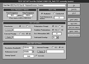
An automated EMI test system is only as good as the software that runs it. The new EMC120 EMI Precompliance Test Software strikes a proper balance between powerful features and ease-of-use. For the new user, there's a HELP Wizard that prompts for the primary steps necessary to define a conducted or radiated test. There's also a complete online manual that's available at the click of a mouse. No longer is it necessary to consult printed manuals to understand how the software works. For the advanced user, there's a complete test-setup screen that allows the important spectrum analyzer parameters to be defined.
The EMC120 package is optimized for the Tektronix 2712 Option 12 Spectrum Analyzer, but it also runs with a standard 2712, or a 2711. The EMC120 automatically controls the Tektronix 2706 Preselector by switching to the appropriate 2706 filter setting as the test is being run.

Figure 1 – The EMC120 Test Setup Screen.
File Operations
A library of typical test routines, with commonly used limit lines, is provided with the software. These support commercial testing according to standards such as CISPR 11, CISPR 22, FCC Part 15 (Class A and B), and the European Norms standards. You can either define a new test from scratch, open a file for an existing test, or modify an existing test and save it to disk. User-defined limit lines can be easily created or modified and saved to disk.
The EMC120 Software also has the ability to store and recall acquired data to/from disk. Either one or two stored data sets can be recalled and graphed on the PC display screen. Using the Import Data function, it's also possible to read in scan data previously acquired through S26EM12, a Tektronix DOS-based EMI software package.
Test Setup
The Test Setup screen (see Figure 1) was designed so that commonly used spectrum analyzer test parameters are readily accessible. These include items such as the Start/Stop Frequency, Reference Level, Resolution Bandwidth, and Sweep Speed. A frequency-band table allows precise control over each acquisition window on the 2712. This software also supports either an external preamp or the internal 2712 preamp, thereby increasing the noise margin relative to stringent EMC limit lines.
Limit lines and correction factors are created in an intuitive spreadsheet-style format. Graphs of these limit lines and correction factors may be displayed on the PC screen or sent to an external printer. Up to 10 different correction factor files can be added together in the software that will be used to correct the data. Up to three limit lines can be simultaneously displayed on the graph of the final data.
The Test Setup screen also allows control of an Electro-Metrics automated mast and turntable.
Running the Test
Three detector modes are available when using a 2712 Option 12: Peak, Quasi-peak, and Average (the Average detector is simulated by using the 2712 video filter). During Peak testing, data may be accumulated in Maxhold mode over a specified number of sweeps, or the data may be accumulated continuously until terminated by the user. Data can also be acquired periodically at specified time intervals - this is useful for radio monitoring and ambient testing. The Quasi-peak and Average tests allow the dwell time to be set so that intermittent signals can be captured.
All data is stored in an internal database using one of three options: Auto-save (append new scan to previous scan), Prompt (save each scan to a specified file), or Auto-overwrite (erase previous scan and store new scan). When recalling Auto-saved data, the user can specify either one or two scans to graph on the screen.
Viewing the Data
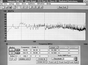
As a test is being run, data is graphed as it is acquired. Once a test has completed, it's possible to enable one or two markers which provide absolute or relative frequency/amplitude values. These markers may be used to highlight selected portions of the graph so that a Zoom-in operation can be performed. Successive Zoom-in operations allow the user to examine signals in greater detail.
There are also three peak-find buttons. A Threshold button allows setting a level below which signals will be ignored. The user has complete control over the display of the graph. The color of each graph element is user definable, and the frequency scale may be set to either Log or Linear. Data may be graphed according to a fixed set of amplitude limits, or by auto-scaling the data.
If a Quasi-peak or Average test is being run, the graph is drawn and a window with Suspect Signals pops up on screen. You can then run a test on each of these signals, or edit the list (add or delete signals) prior to executing the QP or Average test.

Figure 2 – Graph of EMC120 data.
Report Generation
EMC120 Software has a very versatile report generator. Each of the columns in the tabular report is user definable and can include elements such as the frequency of the signal, the peak amplitude, the limit line, etc. The report may be displayed on the screen or sent to a printer.
Pass/Fail Criteria
The software contains a report threshold that operates with respect to the primary limit line. For example, if a value of 10 dB is specified, any signal that is greater than 10 dB below the limit line will be reported. This feature allows the user to effectively select a "pass/fail" criteria for equipment being tested.
System Requirements
EMC120 Software runs on a PC-compatible computer equipped with a National Instruments GPIB (IEEE 488.2) card. A 486/33 or faster processor with at least 8 MB of RAM is recommended. A VGA monitor and hard disk with at least 10 MB of free space is required.
Characteristics
Following are the primary specifications and features for the individual components that make up the 27120B.
2712 Opt. 12 Spectrum Analyzer
Frequency Range - 9 kHz to 1.8 GHz
Center Frequency Accuracy - 5 × 10⁻⁷ of CF ±700 Hz
Flatness (with 10 dB Internal RF Attenuation) - ±1.5 dB (Preamp Off)
Features -
Quasi-peak detector and EMC filters
Built-in frequency counter
True analog plus four-signal digital display
Built-in antenna factor tables
AM/FM demodulators standard
EMC120 Test Software
System Requirements - PC-compatible computer equipped with a National Instruments GPIB (IEEE 488.2) card. 486/33 or faster processor with at least 8 MB of RAM. A VGA and hard disk with at least 10 MB of free space is required.
NOTE: The 27120B does not include a GPIB controller or GPIB cables. These are available from Tektronix. For more information, contact your nearest Tektronix Field Office, or call 1-800-TEK WIDE.
RF Probe Set
Useable to 1 GHz
3 H-field probes
2 E-field probes
Extension
Case
2706 Stepping RF Preselector (Opt. 17)
Frequency Range - 9 kHz to 1.8 GHz
Bandpass/Highpass Filters - Eight spanning the full frequency range
Insertion Loss - 3 dB <1 GHz
Ultimate Rejection - Typically 60 dB below 500 MHz and 30 dB min. above 500 MHz
Features -
Single-switch bypass function
Manual or GPIB control
LISN (Opt. 16)
Facilitates conducted emissions.
Frequency Range - 9 kHz to 100 MHz
Features -
Includes 50-ohm terminator
5-ohm/5-mH measurement circuit
250-mH choke to attenuate noise on incoming mains
Power Line - DC to 400 Hz, 25-A max. continuous, two lines
Transient Limiter (Opt. 16)
Use with LISN to prevent inadvertent damage to spectrum analyzer.
Input Power - 10 W average, 10 kW for 10 µs transients
Attenuation - Constant 10 dB ±0.5 dB from 9 kHz to 100 MHz
Antennas (Opt. 11)
Only two antennas required to cover the entire EC/FCC 1-GHz radiated measurement range.
Biconical - Usable from 20 MHz to 300 MHz.
Log Periodic - Usable from 200 MHz to 1 GHz.
Features -
Hard-copy and disk-based antenna factors included.
Eliminates need for dipole element switching, extension, tuning.


