By Josh Brown
Writing test code can be challenging enough on its own but add poring over the instrument programming manual to extract the right series of commands and you may quickly find yourself with a headache. It would stand to reason that you could save considerable time if your instrument just told you how to program it. The good news is that if you select the right piece of equipment, this is entirely possible. In case you are wondering, no, we do not list a magic crystal ball that predicts code requirements as an accessory on any of the Tektronix or Keithley product data sheets (upper management will not accept the idea – I fear they do not believe in magic). But I digress.

In the following examples, we use the Keithley touchscreen enabled instruments to provide three means of obtaining your setup commands directly from the equipment. Each example is based on a different Keithley instrument model, however the actions are, in practice, the same, and can be performed similarly on any of the touchscreen instruments available from the Keithley product line, including:
- 2450 SourceMeter SMU Instrument, 20W
- 2460 SourceMeter SMU Instrument, 100W, 7A
- 2461 SourceMeter SMU Instrument 1000W, 10A Pulse
- DMM7510 7 ½-Digit Graphical Sampling Multimeter
- DMM6500 6 ½-Digit Bench/System DMM
- DAQ6510 Data Acquisition and Logging Multimeter System.
Save setup method
For the first example, we’ll be using the DAQ6510 to create a script that scans five temperature points. If you have zero interest in multi-channel measurement and switching systems, you may want to skip this section. However, if you are interested in learning more then you may also want to check out the DAQ Primer from Keithley that covers all the basics and then some. Even if this particular application is not of interest to you, we will note that the actions of obtaining the setup information may still be applicable to and benefit you. We will repeat that last sentence a couple times moving forward so you do not lose sight of this fact.
In this example, we will set up the DAQ6510 and Model 7700 Multiplexer Card to make a series of five different temperature measurements on our device under test (DUT), and repeat this each minute for an hour.
- Set the TERMINALS switch on the instrument front panel to REAR.
- Press the MENU key and navigate to Channel->Scan.
- Touch the + button above the Add Group of Channels text.
- Select channels 101 through 105 from the dialog options then touch OK.
- Select Temperature as the Measurement Function.
- In the right-hand pane, touch the Scan tab.
- Set the Count to 60 then set the Scan to Scan Interval to 60 s.
- Navigate to MENU->Scripts->Save Setup.
- Touch the Create button.
- Name the setup “TempScan5Chan” then touch OK to accept and save. At this point the setup is saved, but we want to look at the script on a computer, so we’ll continue.

- Press the EXIT key, and then navigate to Scripts->Manage.
- Insert a USB thumb drive into the DAQ6510.
- Touch TempScan5Chan to highlight it in the Internal Scripts list box, then touch the > button to copy it to the USB thumb drive.


If we then move the USB thumb drive to a computer and open the TempScan5Chan.tsp file, we can verify that the contents cleanly list the commands needed to perform the very same setup via remote programming.

The above image is only a portion of the setup commands generated. Listing everything that was provided just eats up page space. If you are eager to see all the output from this exercise we would encourage you to try it yourself to get the rest. Even so, there is still one final command that is needed to start the scanning process:
trigger.model.initiate()
Notice that this command isn’t included even in the full readout of the setup script, this is due to the nature of the method we used: Save Setup. Initiating a Trigger Model is an action, not an attribute, so it is not listed as part of the setup information. The next two methods we use will record actions, so look out for this very important command towards the end of the next two scripts.
Record a macro method
In this example, we’ll look at the process of creating a script to digitize a current pulse using the DMM7510 digital multimeter. If you’re not interested in DMM operation, you may want to jump ahead to the next section. For anyone coming up to speed on DMMs, I encourage you to read “What is as Digital Multimeter.” Even if this particular application is not of interest to you, we will note that the actions of obtaining the setup information may still be applicable to and benefit you. (See, we told you we would repeat this sentence!)
Let us say that you are interested in evaluating a particular event of a wireless device that will draw in excess of 5 mA for less than 1 s (perhaps this is when the microprocessor comes out of standby mode and polls one of the peripheral sensors). We can capture the current profile of this event by configuring via the front panel and generate the list of commands as we go by recording a macro of all the settings we apply:
- On the instrument front panel, press the MENU key then navigate to Scripts->Record
- Next to the Start Macro label, touch Start
- Press the HOME key and on the FUNCTIONS swipe screen touch the Digi I option.
- Left swipe to SETTINGS and change the Sample Rate to 50,000 and the Count to 50,000 (enabling sampling for a 1 second period), then touch Setup Trigger.
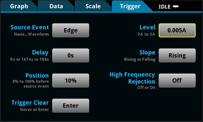
- Touch the button adjacent to Source Event and choose Waveform from the options in the provided dialog. Then choose Analog Edge from the waveform options provided.
- Touch the button adjacent to Position and set to 10% (so that the captured waveform will be shown on the Graph with the detected event starting at the ten percent point along the x-axis).
- Touch the button adjacent to Level and set to 5 mA. Note all the trigger settings applied in the following figure.
- Press the TRIGGER key on the instrument front panel.
- Select Yes to the dialog box, then Initiate Trigger Model (This moves the DMM7510 out of Continuous Measure mode and ready’s our trigger).
- Navigate to MENU->Scripts->Record and touch the Stop button next to the Stop Macro label.
- When presented with the Macro Script Name entry dialog, name the macro “digitizePulse” then touch the OK button.
- Insert a USB thumb drive into the port on the front of the DMM7510.
- Navigate to MENU->Scripts->Manage.
- Touch digitizePulse to highlight in the Internal Scripts list box, then touch the > button to copy it to the USB thumb drive.


If we then move the USB thumb drive to a computer and open the digitizePulse.tsp file, we can verify the contents are detailing the commands needed to perform the same setup via remote programming.

Event log method
In this example, we’ll use the 2450 SourceMeter instrument to build a DC current sweep. If you have made it all the way to the final example you may likely fall into one of the three categories:
- You are very interested in all three methods of getting commands directly from your instrument.
- You skipped ahead to the SourceMeter (a.k.a. “source measure unit” or “SMU”) example because that is really all you care about and you only need one method to get your commands.
- None of this content is relevant to you; your code is compiling in the background; and you need something to keep your eyes busy while you wait.
For those unfamiliar with what a SourceMeter does:
- It precisely sources and measures voltage and/or current at the same time
- It can source and measure across a broad range of voltage and current with up to 6 ½ digits of resolution.
- It can be configured to measure just voltage, current, or resistance.
- It can act as an electronic load
- It can act as a pulse generator
Even if this particular application is not of interest to you, we will note that the actions of obtaining the setup information may still be applicable to and benefit you. (We repeated this sentence again – now I wonder if this compels any text skippers to go back and read the other sections.)
A common operation for the 2450 SMU to perform is sourcing a range of current levels to a target DUT. Let’s extract the minimum number of commands needed to program a 2450 SourceMeter to sweep current from 0 to 10 mA in 0.1 mA steps.
- Press the MENU key and navigate to System->Event Log.
- Touch the Log Settings tab then touch the Clear Log button (in the lower right-hand corner of the screen).
- In the right side group box, touch the button adjacent to Command and turn command logging On.
- Press MENU again, and then touch the Source/Measure->Quickset icon.
- Touch the SrcV MeasI button (next to the Function label).
- From the right-hand column of options presented in the dialog (Source Current and Measure), select Voltage.
- Press the MENU key and navigate to Source->Sweep.
- Change the Start setting to 0 mA.
- Change the Stop setting to 10 mA.
- Change the Step setting to 0.1 mA.
- In the upper left corner of the SWEEP SETTINGS screen, touch the Generate button.
- Press the HOME key.
- To start the sweep, press the TRIGGER key.
- Insert a USB thumb drive into the port on the front of the 2450.
- Navigate to MENU->System->Event Log and touch the Save to USB button.
- A dialog will appear indicating the event log contents will be written to USB; select the Yes option.
If we then move the USB thumb drive to a computer and open the eventlog.csv file in a text editor, we can verify the contents are detailing the commands needed to perform the same setup via remote programming.

Now, if you are saying to yourself, “Self, that looks more like a plain old text file format than a CSV file format…What is this person doing?” then I have an answer for you. The Event Log stores each entry in a CSV file, but the commands themselves are supposed to be read as text. If we were to open this up in a spreadsheet program, we would lose the commas and inject errors and frustration into our control code. The beauty of recording commands this way is you get to see exactly what the instrument is doing at each button press.
If your next comment is, “Full commands, huh? So, what about line six? The command is cut off.” then I commend you for your powers of observation. You are correct, some commands are just too long for the Event Log to keep track of. The good thing is that most of the work is done for us – even though we will need to cross-check against the instrument Reference Manual, we already know the command to look for. Reviewing smu.source.sweeplinearstep(), we find that the remaining pieces that were cut off are the full buffer name and the ending parentheses. The corrected command should read as follows:
Well you made it made it all the way to the end and with any luck even learned some new tricks that will help you to be more productive. Happy scripting.