연락처
텍트로닉스 담당자와 실시간 상담 6:00am-4:30pm PST에 이용 가능
전화 문의
9:00am-6:00PM KST에 이용 가능
다운로드
매뉴얼, 데이터 시트, 소프트웨어 등을 다운로드할 수 있습니다.
피드백
2 Series MSO Specification and Performance Verification Manual
This document contains the specifications and performance verification procedures for the 2 Series MSO.
이 매뉴얼은 다음에 적용됩니다.:
MSO22, MSO24, MSO22-EDU, MSO24-EDU
By downloading, you agree to the terms and conditions of the Manuals Download Agreement.
Manuals Download Agreement
ATTENTION: please read the following terms and conditions carefully before downloading any documents from this website. By downloading manuals from Tektronix' website, you agree to the following terms and conditions:
Manuals for Products That Are Currently Supported:
Tektronix hereby grants permission and license to owners of Tektronix instruments to download and reproduce the manuals on this website for their own internal or personal use. Manuals for currently supported products may not be reproduced for distribution to others unless specifically authorized in writing by Tektronix, Inc.
A Tektronix manual may have been revised to reflect changes made to the product during its manufacturing life. Thus, different versions of a manual may exist for any given product. Care should be taken to ensure that one obtains the proper manual version for a specific product serial number.
Manuals for Products That Are No Longer Supported:
Tektronix cannot provide manuals for measurement products that are no longer eligible for long term support. Tektronix hereby grants permission and license for others to reproduce and distribute copies of any Tektronix measurement product manual, including user manuals, operator's manuals, service manuals, and the like, that (a) have a Tektronix Part Number and (b) are for a measurement product that is no longer supported by Tektronix.
A Tektronix manual may be revised to reflect changes made to the product during its manufacturing life. Thus, different versions of a manual may exist for any given product. Care should be taken to ensure that one obtains the proper manual version for a specific product serial number.
This permission and license does not apply to any manual or other publication that is still available from Tektronix, or to any manual or other publication for a video production product or a color printer product.
Disclaimer:
Tektronix does not warrant the accuracy or completeness of the information, text, graphics, schematics, parts lists, or other material contained within any measurement product manual or other publication that is not supplied by Tektronix or that is produced or distributed in accordance with the permission and license set forth above.
Tektronix may make changes to the content of this website or to its products at any time without notice.
Limitation of Liability:
TEKTRONIX SHALL NOT BE LIABLE FOR ANY DAMAGES WHATSOEVER (INCLUDING, WITHOUT LIMITATION, ANY CONSEQUENTIAL OR INCIDENTAL DAMAGES, DAMAGES FOR LOSS OF PROFITS, BUSINESS INTERRUPTION, OR FOR INFRINGEMENT OF INTELLECTUAL PROPERTY) ARISING OUT OF THE USE OF ANY MEASUREMENT PRODUCT MANUAL OR OTHER PUBLICATION PRODUCED OR DISTRIBUTED IN ACCORDANCE WITH THE PERMISSION AND LICENSE SET FORTH ABOVE.
Read Online
SPECIFICATIONS
- Analog signal acquisition system
- Triggering system
- Digital channel acquisition
- Digital pattern generator
- Arbitrary function generator
- Processor system
- Display system
- Interfaces, input, and output ports
- Data handling characteristics
- Power supply system
- Safety characteristics
- Mechanical characteristics
- Electromagnetic compatibility
- Environmental
- Regulatory compliance
Important safety information
This manual contains information and warnings that must be followed by the user for safe operation and to keep the product in a safe condition.
To safely perform service on this product, see the Service safety summary that follows the General safety summary.
General safety summary
Use the product only as specified. Review the following safety precautions to avoid injury and prevent damage to this product or any products connected to it. Carefully read all instructions. Retain these instructions for future reference.
This product shall be used in accordance with local and national codes.
For correct and safe operation of the product, it is essential that you follow generally accepted safety procedures in addition to the safety precautions specified in this manual.
The product is designed to be used by trained personnel only.
Only qualified personnel who are aware of the hazards involved should remove the cover for repair, maintenance, or adjustment.
Before use, always check the product with a known source to be sure it is operating correctly.
This product is not intended for detection of hazardous voltages.
Use personal protective equipment to prevent shock and arc blast injury where hazardous live conductors are exposed.
While using this product, you may need to access other parts of a larger system. Read the safety sections of the other component manuals for warnings and cautions related to operating the system.
When incorporating this equipment into a system, the safety of that system is the responsibility of the assembler of the system.
To avoid fire or personal injury
Use proper power cord
Use only the power cord specified for this product and certified for the country of use. Do not use the provided power cord for other products.
Ground the product
This product is grounded through the grounding conductor of the power cord. To avoid electric shock, the grounding conductor must be connected to earth ground. Before making connections to the input or output terminals of the product, ensure that the product is properly grounded. Do not disable the power cord grounding connection.
Power disconnect
The power cord disconnects the product from the power source. See instructions for the location. Do not position the equipment so that it is difficult to operate the power cord; it must remain accessible to the user at all times to allow for quick disconnection if needed.
Use proper AC adapter
Use only the AC adapter specified for this product.
Connect and disconnect properly
Do not connect or disconnect probes or test leads while they are connected to a voltage source.
Use only insulated voltage probes, test leads, and adapters supplied with the product, or indicated by Tektronix to be suitable for the product.
Connect the probe output to the measurement instrument before connecting the probe to the circuit under test. Connect the probe reference lead to the circuit under test before connecting the probe input. Disconnect the probe input and the probe reference lead from the circuit under test before disconnecting the probe from the measurement instrument.
De-energize the circuit under test before connecting or disconnecting the current probe.
Observe all terminal ratings
To avoid fire or shock hazard, observe all rating and markings on the product. Consult the product manual for further ratings information before making connections to the product.
Do not exceed the Measurement Category (CAT) rating and voltage or current rating of the lowest rated individual component of a product, probe, or accessory. Use caution when using 1:1 test leads because the probe tip voltage is directly transmitted to the product.
Do not apply a potential to any terminal, including the common terminal, that exceeds the maximum rating of that terminal.
Do not float the common terminal above the rated voltage for that terminal.
The measurement terminals on this product are not rated for connection to Category III or IV circuits.
Do not connect a current probe to any wire that carries voltages above the current probe voltage rating.
Do not operate without covers
Do not operate this product with covers or panels removed, or with the case open. Hazardous voltage exposure is possible.
Avoid exposed circuitry
Do not touch exposed connections and components when power is present.
Do not operate with suspected failures
If you suspect that there is damage to this product, have it inspected by qualified service personnel.
Disable the product if it is damaged. Do not use the product if it is damaged or operates incorrectly. If in doubt about safety of the product, turn it off and disconnect the power cord. Clearly mark the product to prevent its further operation.
Before use, inspect voltage probes, test leads, and accessories for mechanical damage and replace when damaged. Do not use probes or test leads if they are damaged, if there is exposed metal, or if a wear indicator shows.
Examine the exterior of the product before you use it. Look for cracks or missing pieces.
Use only specified replacement parts.
Replace batteries properly
Replace batteries only with the specified type and rating.
Recharge batteries for the recommended charge cycle only.
Wear eye protection
Wear eye protection if exposure to high-intensity rays or laser radiation exists.
Do not operate in wet/damp conditions
Be aware that condensation may occur if a unit is moved from a cold to a warm environment.
Do not operate in an explosive atmosphere
Keep product surfaces clean and dry
Remove the input signals before you clean the product.
Provide proper ventilation
Refer to the installation instructions in the manual for details on installing the product so it has proper ventilation.
Slots and openings are provided for ventilation and should never be covered or otherwise obstructed. Do not push objects into any of the openings.
Provide a safe working environment
Always place the product in a location convenient for viewing the display and indicators.
Avoid improper or prolonged use of keyboards, pointers, and button pads. Improper or prolonged keyboard or pointer use may result in serious injury.
Be sure your work area meets applicable ergonomic standards. Consult with an ergonomics professional to avoid stress injuries.
Use only the Tektronix rackmount hardware specified for this product.
Probes and test leads
Before connecting probes or test leads, connect the power cord from the power connector to a properly grounded power outlet.
Keep fingers behind the protective barrier, protective finger guard, or tactile indicator on the probes. Remove all probes, test leads and accessories that are not in use.
Use only correct Measurement Category (CAT), voltage, temperature, altitude, and amperage rated probes, test leads, and adapters for any measurement.
Beware of high voltages
Understand the voltage ratings for the probe you are using and do not exceed those ratings. Two ratings are important to know and understand:
- The maximum measurement voltage from the probe tip to the probe reference lead.
- The maximum floating voltage from the probe reference lead to earth ground.
These two voltage ratings depend on the probe and your application. Refer to the Specifications section of the manual for more information.
 | WARNING:To prevent electrical shock, do not exceed the maximum measurement or maximum floating voltage for the oscilloscope input BNC connector, probe tip, or probe reference lead. |
Connect and disconnect properly.
Connect the probe output to the measurement product before connecting the probe to the circuit under test. Connect the probe reference lead to the circuit under test before connecting the probe input. Disconnect the probe input and the probe reference lead from the circuit under test before disconnecting the probe from the measurement product.
De-energize the circuit under test before connecting or disconnecting the current probe.
Connect the probe reference lead to earth ground only.
Do not connect a current probe to any wire that carries voltages or frequencies above the current probe voltage rating.
Inspect the probe and accessories
Before each use, inspect probe and accessories for damage (cuts, tears, or defects in the probe body, accessories, or cable jacket). Do not use if damaged.
Ground-referenced oscilloscope use
Do not float the reference lead of this probe when using with ground-referenced oscilloscopes. The reference lead must be connected to earth potential (0 V).
Floating measurement use
Do not float the reference lead of this probe above the rated float voltage.
Service safety summary
The Service safety summary section contains additional information required to safely perform service on the product. Only qualified personnel should perform service procedures. Read this Service safety summary and the General safety summary before performing any service procedures.
To avoid electric shock
Do not touch exposed connections.
Do not service alone
Do not perform internal service or adjustments of this product unless another person capable of rendering first aid and resuscitation is present.
Disconnect power
To avoid electric shock, switch off the product power and disconnect the power cord from the mains power before removing any covers or panels, or opening the case for servicing.
Use care when servicing with power on
Dangerous voltages or currents may exist in this product. Disconnect power, remove battery (if applicable), and disconnect test leads before removing protective panels, soldering, or replacing components.
Verify safety after repair
Always recheck ground continuity and mains dielectric strength after performing a repair.
Terms in this manual
These terms may appear in this manual:
| WARNING:Warning statements identify conditions or practices that could result in injury or loss of life. |
| CAUTION:Caution statements identify conditions or practices that could result in damage to this product or other property. |
Terms on the product
These terms may appear on the product:
- DANGER indicates an injury hazard immediately accessible as you read the marking.
- WARNING indicates an injury hazard not immediately accessible as you read the marking.
- CAUTION indicates a hazard to property including the product.
Symbols on the product
 | When this symbol is marked on the product, be sure to consult the manual to find out the nature of the potential hazards and any actions which have to be taken to avoid them. (This symbol may also be used to refer the user to ratings in the manual.) |
The following symbols(s) may appear on the product.
 CAUTION: Refer to Manual |  Protective Ground (Earth) Terminal |  Earth Terminal |  Chassis Ground |  WARNING: High Voltage |  Breakable. Do not drop. |
 Standby |  Functional Earth Terminal |  Use only on an insulated wire. |  Connection and disconnection to hazardous bare wire permitted. |  Do not connect to or remove from an uninsulated conductor that is HAZARDOUS LIVE. |
Specifications
This chapter contains specifications for the instrument. All specifications are typical unless noted as guaranteed. Typical specifications are provided for your convenience but are not guaranteed. Specifications that are marked with the ✔ symbol are guaranteed and checked in Performance Verification.
- The instrument must have been calibrated in an ambient temperature between 18 °C and 28 °C (64 °F and 82 °F).
- The instrument must be operating within the environmental limits. (See Environmental characteristics).
- The instrument must be powered from a source that meets the specifications. (See Power supply system).
- The instrument must have been operating continuously for at least 20 minutes within the specified operating temperature range.
- You must perform the Signal path compensation procedure after the warmup period. See the Signal path compensation procedure for how to perform signal path compensation. If the ambient temperature changes more than 5 °C (9 °F), repeat the procedure.
Analog signal acquisition system
- Analog input channels
- MSO22: 2 channel
- Input coupling
- AC, DC
- Input termination selection
- 1 MΩ only
- Input termination, 1 MΩ DC-coupled
- 1 MΩ ± 1%
- Input capacitance, 1 MΩ DC-coupled
- 14 pF ± 3 pF
- Digitized bits
- 8 bits
- Sensitivity range (coarse), 1 MΩ
- 1 mV/Div to 10 V/Div in a 1-2-5 sequence
- Sensitivity range (fine)
- Continuous adjustment from 1 mV/DIV to 10 V/DIV, 1 MΩ 1x
- Sensitivity resolution (fine)
- ≤10% of current setting
- Maximum input voltage, 1 MΩ DC-coupled
- Maximum input voltage at the BNC, 300 Vrms. Installation category II
- ✔ DC gain accuracy
- Guaranteed for 2 mV/div and above, typical otherwise. Specification valid after 30 minute warm-up and Signal Path Compensation (SPC) at ambient.
- Offset ranges
- 1 mV/div to 63.8 mV/div : ±1 V
- Position range
- ±5 divisions
- Offset accuracy
- All terms must be converted to volts by multiplying by the current volts/div setting.
- Waveforms for average acquisition mode
- 2 to 10.24 k waveforms; default of 16 waveforms
- DC voltage measurement accuracy, average acquisition mode
- The basic accuracy specification applies directly to any sample and to the following measurements: high, low, maximum, minimum, mean, cycle mean, RMS, and cycle RMS. The delta volts accuracy specification applies to subtractive calculations involving two of these measurements. The delta volts (difference voltage) accuracy specification applies directly to the following measurements; positive overshoot, negative overshoot, Pk-Pk, and amplitude.
- Bandwidth selections
- 20 MHz, 70 MHz, 100 MHz, 200 MHz, 350 MHz, and 500 MHz (when equal to or less than instrument's rated bandwidth)
- ✔ Analog bandwidth
- Below 5 mV/div, 500 MHz bandwidth is specified as typical.
- Lower frequency limit, AC-coupled
- <10 Hz
- Upper frequency limit, 20 MHz bandwidth-limited
- 20 MHz, ± 25%, DC-coupled
- Calculated rise time
- Measurements made using the oscilloscope's automated measurement feature may read slower rise time values than those determined by the above equation. This is because the automated measurements do not take interpolation into account. Measuring using cursors on the interpolated waveform gives a more accurate result.
- Peak detect or envelope mode pulse response
- Peak detect response indicates how effective the oscilloscope is at picking up a single narrow pulse and determining its amplitude.
- Deskew range
- -95 ns to +95 ns
- Crosstalk (channel isolation)
-
≤ 100 MHz > 100 MHz 1 MΩ 100:1 30:1 - Sample rate range
- Maximum 1.25 GS/s - All channels
- Record length range
- 10 M Standard
- Seconds/Division range
- 1 ns/div to 1000 s/div when in half channel mode
- Maximum triggered acquisition rate
- >5k wfm/s
- ✔ Timebase accuracy
- ± 25 x 10-6 over any over any ≥1 ms interval
- Timebase delay time range
- -10 divisions to 5000 s
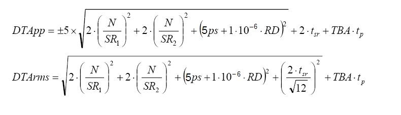
- Delta time measurement accuracy (DTA)
- The formula to calculate delta-time measurement accuracy (DTA) for a given instrument setting and input signal is as follows (assumes insignificant signal content above the Nyquist frequency).
SR1 = Slew rate (1st Edge) around 1st point in measurement
SR2 = Slew rate (2nd Edge) around 2nd point in measurement
N = Input-referred noise (Vrms)
TBA = Timebase accuracy
tp = Delta-time measurement duration (sec)
RD = (Record length)/(Sample rate)
(assume edge shape that results from Gaussian filter response)

(Assumes insignificant error due to aliasing)
Triggering system
- Aux In (external) trigger channels
- One channel
- Aux In (external) trigger input impedance
- 1 MΩ ± 1% in parallel with 14 pF ± 3 pF
- Aux In (external) trigger maximum input voltage
- 300 Vrms, Installation category II
- Edge-type trigger sensitivity, DC-coupled
- The greater of 2 mV or 0.4 div from DC to 20 MHz
- Edge trigger sensitivity, AC-coupled
- The minimum sensitivities are as follows:
Trigger coupling Typical sensitivity AC 1.0 times the DC coupled limits for frequencies above 10 Hz. Attenuates signals below 10 Hz NOISE REJ 2.5 times the DC coupled limits HF REJ 1.0 times the DC coupled limits from DC to 50 kHz. Attenuates signals above 50 kHz LF REJ 1.0 times the DC Coupled limits for frequencies above 50 kHz. Attenuates signals below 50 kHz - Trigger modes
- Auto, normal, and single
- Trigger coupling
- DC, HF Reject (attenuates > 50 kHz), LF Reject (attenuates < 50 kHz), noise reject (reduces sensitivity)
- Trigger level ranges
-
- Any input channel
- ±5 divisions from center of screen
- Aux In
- ±8 V
- Trigger types
-
- Edge
- Positive, negative, or either slope on any channel.
- Pulse Width
- Trigger on width of positive or negative pulses. Event can be time- or logic-qualified.
- Timeout
- Trigger on an event which remains high, low, or either, for a specified time period. Event can be logic-qualified.
- Runt
- Trigger on a pulse that crosses one threshold but fails to cross a second threshold before crossing the first again. Event can be time- or logic-qualified.
- Logic
- Trigger when logic pattern goes true, goes false, or occurs coincident with a clock edge. Pattern (AND, OR, NAND, NOR) specified for all input channels defined as high, low, or don't care. Logic pattern going true can be time-qualified.
- Setup/Hold
- Trigger on violations of both setup time and hold time between clock and data present on any input channels.
- Rise/Fall
- Trigger on pulse edge rates that are faster or slower than specified. Slope may be positive, negative, or either. Event can be logic-qualified.
- Parallel (with MSO option)
- Trigger on a parallel bus data value. Parallel bus can be from 1 to 20 bits (from the digital and analog channels) in size. Supports binary and hex radices.
- I2C (option)
- Trigger on start, repeated start, stop, missing ack, address (7 or 10 bit), data, or address and data on I2C buses up to 10 Mb/s.
- SPI (option)
- Trigger on slave select, idle time, or data (1-16 words) on SPI buses up to 20 Mb/s.
- RS-232/422/485/UART (option)
- Trigger on start bit, end of packet, data, and parity error up to 15 Mb/s.
- CAN (option)
- Trigger on start of frame, type of frame (data, remote, error, or overload), identifier, data, identifier and data, end of frame, missing ack, and bit stuff error on CAN buses up to 1 Mb/s and CAN-FD buses up to 16 Mb/s.
- LIN (option)
- Trigger on sync, identifier, data, identifier and data, wakeup frame, sleep frame, and error on lin buses up to 1 Mb/s.
- SENT (option)
- Trigger on start of packet, fast channel status and data, slow channel message ID and data, and CRC errors.
- Lowest frequency for successful operation of "Set level to 50%" function
- 50 Hz
- Logic trigger minimum logic or rearm time
- For logic, time between channels refers to the length of time a logic state derived from more than one channel must exist to be recognized. For events, the time is the minimum time between a main and delayed event that will be recognized if more than one channel is used.
- Setup/hold violation trigger, setup and hold time ranges
- Input coupling on the clock and data channels must be the same.
- Minimum pulse width, rearm time, and transition time
- For trigger class width and runt, pulse width refers to the width of the pulse being measured. Rearm time refers to the time between pulses.
- Rise/fall time trigger, delta time range
- 800 ps to 20 s
- Pulse width, or time-qualified runt trigger time range
- 800 ps to 20 s
- Trigger holdoff range
- 0 s minimum to 10 s maximum.
Digital channel acquisition
- Digital input channels
- 16 Digital Inputs [D0:D15]
- Input resistance, typical
- 101 KΩ to ground
- Input capacitance, typical
- 8 pF
- Minimum input signal swing, typical
- 500mV peak-to-peak
- Maximum input signal swing, typical
- +30 V, -20 V
- DC input voltage range
- +30 V, -20 V
- Maximum input dynamic range
- 50 Vpp (threshold setting dependent)
- Channel to channel skew (typical)
- 500 ps
- Thresholds
- Thresholds per set of 8 channels
- Threshold Selections
- TTL, CMOS, ECL, PECL, User-Defined
- Threshold voltage range
- –15 V to +25 V
- Digital channel timing resolution
- Minimum: 2 ns
- ✔ Threshold accuracy
- ± [180 mV + 2% of threshold setting after calibration]. Requires valid SPC.
- Minimum detectable pulse
- 5.0 ns
Digital pattern generator
- Number of channels
- 4
- Pattern memory length
- 4 K bits
- Output amplitude
- 2.5 V, 3.3 V, 5 V (Continuous Mode)
- Bit Rate
- 1 bps to 25 Mbps
- Pattern type
- Square, counter, user defined, and manual
Arbitrary function generator
- Operating modes
- Continuous, burst
- Function types
- Arbitrary, sine, square, pulse, ramp, DC level, Gaussian, Lorentz, exponential rise/fall, sin(x)/x, random noise, Haversine, and Cardiac.
- Amplitude and frequency range
- Values are peak-to-peak voltages.
Waveform Amplitude range 50 Ω Amplitude range 1 MΩ Frequency range Arbitrary 10 mV to 2.5 V 20 mV to 5 V 0.1 Hz to 25 MHz Sine 10 mV to 2.5 V 20 mV to 5 V 0.1 Hz to 50 MHz Square 10 mV to 2.5 V 20 mV to 5 V 0.1 Hz to 20 MHz Pulse 10 mV to 2.5 V 20 mV to 5 V 0.1 Hz to 20 MHz Ramp 10 mV to 2.5 V 20 mV to 5 V 0.1 Hz to 500 KHz DC Level 20 mV to 5V Gaussian 10 mV to 1.25 V 20 mV to 2.5 V 0.1 Hz to 5 MHz Lorentz 10 mV to 1.2 V 20 mV to 2.4 V 0.1 Hz to 5 MHz Exponential rise 10 mV to 1.25 V 20 mV to 2.5 V 0.1 Hz to 5 MHz Exponential decay 10 mV to 1.25 V 20 mV to 2.5 V 0.1 Hz to 5 MHz Sin(X)/X 10 mV to 1.5 V 20 mV to 3.0 V 0.1 Hz to 2 MHz Random noise 10 mV to 2.5 V 20 mV to 5 V Haversine 10 mV to 1.25 V 20 mV to 2.5 V 0.1 Hz to 5 MHz Cardiac 10 mV to 2.5 V 20 mV to 5 V 0.1 Hz to 500 KHz - Maximum sample rate
- 250 MS/s
- Arbitrary function length
- 128 K sample
- Sine waveform
-
- Frequency setting resolution
- 0.1 Hz
- Amplitude flatness
- ±0.5 dB at 1 kHz
- Total harmonic distortion
- 1% into 50 Ω for amplitude > 100 mV
- Spurious-free dynamic range
- 40 dB (Vpp ≥ 0.1 V) 50 Ω load
- Square and pulse waveform
-
- Frequency setting resolution
- 0.1 Hz
- Duty cycle range
- 10% - 90% or 10 ns minimum pulse, whichever is larger
- Minimum pulse width, typical
- 10 ns. This is the minimum time for either on or off duration.
- Rise/fall time
- 5.5 ns, 10% - 90% with 50 Ω termination
- Pulse width resolution
- 100 ps
- Overshoot
- <5% for signal steps > 100 mVpp and frequency settings ≥100 kHz with 50 Ω termination
- Asymmetry
- ± 1% ± 5 ns, at 50% duty cycle with 50 Ω termination
- Jitter
- <500 ps TIErms
- Ramp and triangle waveform
-
- Frequency setting resolution
- 0.1 Hz
- Variable symmetry
- 0% - 100%
- Symmetry resolution
- 0.1%
- DC level range
- ±2.5 V into Hi-Z
- Random noise amplitude range
- 20 mVpp to 5 Vpp in to Hi-Z
- Sine and ramp frequency accuracy
- 130 ppm (frequency ≤10 kHz); 50 ppm (frequency > 10 kHz)
- Square and pulse frequency accuracy
- 130 ppm (frequency ≤10 kHz); 50 ppm (frequency > 10 kHz)
- Signal amplitude resolution
- 500 μV (50 Ω)
- Signal amplitude accuracy
- ±[ (1.5% of peak-to-peak amplitude setting) + (1.5% of absolute DC offset setting) + 1 mV ] (frequency = 1 kHz)
- DC offset Range
- ±2.5 V into Hi-Z
- DC offset Resolution
- 500 μV (50 Ω)
- ✔ DC offset accuracy
- ± [ (1.5% of absolute offset voltage setting) + 1 mV ]
Processor system
- Host processor
- Application processing unit: Dual-core Arm Cortex-A53 MPCore with CoreSight; NEON and single/double precision floating point; 32 KB/32 KB L1 cache, 1 MB L2 cache
Display system
- Display type
- Display area – 217 mm x 135 mm, TFT active matrix, and Liquid Crystal Display (LCD) with capacitive touch.
- Display resolution
- 1,280 horizontal × 800 vertical pixels
- Display modes
- Overlay and stacked
- Luminance
- 260 cd/m²
- Color support
- 16,777,216 (8-bit RGB) colors
- Zoom
- Horizontal and vertical zooming is supported in all waveform and plot views
- Interpolation
- Sin(x)/x and linear
- Waveform styles
- Vectors, dots, variable persistence, and infinite persistence
- Graticules
- Movable and fixed graticules, selectable between grid, time, full, and none
- Color palettes
- Normal and inverted for screen captures
- Format
- YT, XY
- Language support
-
English, Japanese, Simplified Chinese, Traditional Chinese, French, German, Italian, Spanish, Portuguese, Russian, Korean
Interfaces, input, and output ports
- USB interface
- Two USB 2.0 high speed host ports on the side of the instrument
- Ethernet Interface
- One 8-pin RJ-45 connector that supports 10/100 Mb/s and 1000 Mbps Ethernet (in full duplex mode only)
- Probe compensator, output voltage and frequency
-
Characteristic Value Output voltage Normal: 0-2.5 V amplitude Source impedance Normal: 1 kΩ Frequency 1 kHz - Auxiliary output (Aux out)
-
- Aux out connector and functional modes
- A single BNC connector
- Aux out output voltage
- Non-AFG voltage thresholds are listed in the following table:
Characteristic Limits Vout (HI) ≥ 2.5 V open circuit; ≥ 1.0 V into a 50 Ω load to ground Vout (LO) ≤ 0.7 V into a load of ≤ 4 mA; ≤ 0.25 V into a 50 Ω load to ground
- Aux input
- 300 Vrms CAT II with peaks ≤ ±425 V
- Security lock
- Rear-panel security slot connects to standard Kensington-style lock
- VESA mount
- Standard (VESA MIS-D 100) 100 mm x 100 mm VESA mounting points on rear of instrument
- Ground lug
- Provides a safe ground return path when the instrument is operating on battery
Data handling characteristics
- Real-time clock
- A programmable clock maintains and reports the current time in the units of years, months, days, hours, minutes, and seconds.
- Non-volatile memory capacity
- One eMMC device (limited to 2 GB of usable space in SLC mode) contains the bootloader, operating system, application software, calibration constants, and user data storage.
- Mass storage device capacity
- Linux: ≥4 GB.
Power supply system
- Power consumption
- 60 W maximum
- Source voltage
- 100 – 240 VAC ±10% (50/60 Hz)
- Source frequency
- 50 – 60 Hz (100 – 240 VAC)
- AC Adapter output
- 24 V DC, 2.71 A
- Fuse rating
- T3.15 A, 250 V
- Battery
-
- Description
- Requires Opt 2-BATPK or 2-BP battery pack, with 2 slots for batteries
- Cell chemistry
- Li-lon
- Nominal capacity
- 6700 mAh
- Voltage
- 14.52 VDC
- Weight
- 450 g (1 lb)
- Battery operating time, typical
- Up to 4 hours with single battery
Safety characteristics
- Safety certification
- The following certifications and compliance are applicable:
- Pollution degree
- Pollution degree 2, indoor, and dry location use only.
Mechanical characteristics
- Weight
-
- Instrument only
- 1.8 kg (4 lbs)
- Instrument with battery pack
- 3.2 kg (7 lbs) – one battery
- Instrument only dimensions
-
- Height
- 210 mm (8.26 in)
- Width
- 344 mm (13.54 in)
- Depth
- 40.4 mm (1.59 in)
- Instrument with battery pack dimensions
-
- Height
- 210 mm (8.26 in)
- Width
- 344 mm (13.54 in)
- Depth
- 78 mm (3.07 in)
- Clearance requirements
- The clearance requirement for adequate cooling is 13 mm (0.5 in) on the rear of the instrument along the bottom edge (inlet vents) and top edge (exhaust vents).
- Rackmount configuration
- 5U
Electromagnetic compatibility
Regional certifications, classifications, and standards list
- European union
- EC Council EMC Directive 2014/30/EU
- Australia
- EMC Framework, demonstrated per emission standard CISPR 11 in accordance with EN 61326-2-1.
- United Kingdom
- Electromagnetic Compatibility Regulations 2016-UK SI 2016 No.1091
- Ukraine
- Technical Regulations on Electromagnetic Equipment Compatibility TR 1077
- Korea
- EC Council EMC Directive 2014/30/EU
Immunity
- Electrostatic discharge (ESD), and enclosure port
- IEC 61000-4-2
- Radiated radio frequency electromagnetic field, and enclosure port
- IEC 61000-4-3
- Electrical fast Transient/burst, and common-mode
- IEC 61000-4-4
- Surge/electrical slow transient
- IEC 61000-4-5
- Conducted radio frequency
- IEC 61000-4-6
- Voltage dips and short interruptions, and AC power port
- IEC 61000-4-11
Environmental
- Product recycling information and documentation
- User information should include an explanation of the recycling mark and direct the customer to the appropriate resources for recycling the product via one of the following methods:
- Operator manual boilerplate; or
- Pack-in errata sheet (only use this method if manual has been finalized); or
- Online help file (if no other documentation is shipped with the product).
- Temperature
-
- Operating
- 0 °C to +50 °C (+32 °F to 120 °F)
- Operating battery
- 0 °C to 45 °C (+32 °F to 113 °F)
- Non-operating
- -20 °C to +60 °C (-4 °F to 140 °F)
- Humidity
-
- Operating
- 5% to 90% relative humidity at temperatures up to +30 °C,
- Non-operating
- 5% to 90% relative humidity at temperatures up to +30 °C
- Altitude
-
- Operating
- Up to 3,000 meters (9,842 feet)
- Non-operating
- Up to 12,000 meters (39,370 feet)
Regulatory compliance
- EMC
- Conforms to European Union EMC Directive (CE-marked)
- Safety
- Conforms to European Union Low Voltage Directive (CE-marked)
- RoHS
- Conforms to European Union Restrictions on Hazardous Substances (CE-marked)
Performance verification procedures
This chapter contains performance verification procedures for the specifications marked with the ✔ symbol. The following equipment, or a suitable equivalent, is required to complete these procedures.
The performance verification procedures verify the performance of your instrument. They do not adjust your instrument. If your instrument fails any of the performance verification tests, repeat the failing test, verifying that the test equipment and settings are correct. If the instrument continues to fail a test, contact Tektronix Customer Support for assistance.
These procedures cover all 2 Series MSO instruments. Completion of the performance verification procedure does not update the instrument time and date.
Print the test records on the following pages and use them to record the performance test results for your oscilloscope. Disregard checks and test records that do not apply to the specific model you are testing.
The following table lists the required equipment. You might need additional cables and adapters, depending on the actual test equipment you use.
| Required equipment | Minimum requirements | Examples |
|---|---|---|
| DC voltage source | 3 mV to 4 V, ±0.1% accuracy | Fluke 9500B Oscilloscope Calibrator with a 9530 Output Module |
| Leveled sine wave generator | 50 kHz to 2 GHz, ±4% amplitude accuracy | |
| Time mark generator | 80 ms period, ±1.0 x 10⁻⁶ accuracy, rise time <50 ns |
Test records
DC Gain Accuracy test record
| DC Gain Accuracy | |||||
|---|---|---|---|---|---|
| Performance checks | Bandwidth | Vertical scale | Low limit | Test result | High limit |
| Channel 1 DC Gain Accuracy, 0 V offset, 0 V vertical position | 20 MHz | 2 mV/div | -2% | 2% | |
| 4.98 mV/div | -2% | 2% | |||
| 5 mV/div | -2% | 2% | |||
| 10 mV/div | -2% | 2% | |||
| 20 mV/div | -2% | 2% | |||
| 49.8 mV/div | -2% | 2% | |||
| 50 mV/div | -2% | 2% | |||
| 100 mV/div | -2% | 2% | |||
| 200 mV/div | -2% | 2% | |||
| 500 mV/div | -2% | 2% | |||
| 1 V/div | -2% | 2% | |||
| FULL | 100 mV/div | -2% | 2% | ||
| Channel 2 DC Gain Accuracy, 0 V offset, 0 V vertical position | 20 MHz | 2 mV/div | -2% | 2% | |
| 4.98 mV/div | -2% | 2% | |||
| 5 mV/div | -2% | 2% | |||
| 10 mV/div | -2% | 2% | |||
| 20 mV/div | -2% | 2% | |||
| 49.8 mV/div | -2% | 2% | |||
| 50 mV/div | -2% | 2% | |||
| 100 mV/div | -2% | 2% | |||
| 200 mV/div | -2% | 2% | |||
| 500 mV/div | -2% | 2% | |||
| 1 V/div | -2% | 2% | |||
| FULL | 100 mV/div | -2% | 2% | ||
| Channel 3 DC Gain Accuracy, 0 V offset, 0 V vertical position | 20 MHz | 2 mV/div | -2% | 2% | |
| 4.98 mV/div | -2% | 2% | |||
| 5 mV/div | -2% | 2% | |||
| 10 mV/div | -2% | 2% | |||
| 20 mV/div | -2% | 2% | |||
| 49.8 mV/div | -2% | 2% | |||
| 50 mV/div | -2% | 2% | |||
| 100 mV/div | -2% | 2% | |||
| 200 mV/div | -2% | 2% | |||
| 500 mV/div | -2% | 2% | |||
| 1 V/div | -2% | 2% | |||
| FULL | 100 mV/div | -2% | 2% | ||
| Channel 4 DC Gain Accuracy, 0 V offset, 0 V vertical position | 20 MHz | 2 mV/div | -2% | 2% | |
| 4.98 mV/div | -2% | 2% | |||
| 5 mV/div | -2% | 2% | |||
| 10 mV/div | -2% | 2% | |||
| 20 mV/div | -2% | 2% | |||
| 49.8 mV/div | -2% | 2% | |||
| 50 mV/div | -2% | 2% | |||
| 100 mV/div | -2% | 2% | |||
| 200 mV/div | -2% | 2% | |||
| 500 mV/div | -2% | 2% | |||
| 1 V/div | -2% | 2% | |||
| FULL | 100 mV/div | -2% | 2% | ||
Analog Bandwidth test record
| Analog Bandwidth performance checks | |||||
|---|---|---|---|---|---|
| Bandwidth at Channel | Vertical scale | Vin-AC RMS | Vbw-AC RMS | Limit | Test result Gain = Vbw-AC RMS/Vin-AC RMS |
| Channel 1 | 1 mV/div | ≥ 0.707 | |||
| 2 mV/div | ≥ 0.707 | ||||
| 5 mV/div | ≥ 0.707 | ||||
| 10 mV/div | ≥ 0.707 | ||||
| 20 mV/div | ≥ 0.707 | ||||
| 200 mV/div | ≥ 0.707 | ||||
| 700 mV/div | ≥ 0.707 | ||||
| 3 V/div | ≥ 0.707 | ||||
| 5 V/div | ≥ 0.707 | ||||
| Channel 2 | 1 mV/div | ≥ 0.707 | |||
| 2 mV/div | ≥ 0.707 | ||||
| 5 mV/div | ≥ 0.707 | ||||
| 10 mV/div | ≥ 0.707 | ||||
| 20 mV/div | ≥ 0.707 | ||||
| 200 mV/div | ≥ 0.707 | ||||
| 700 mV/div | ≥ 0.707 | ||||
| 3 V/div | ≥ 0.707 | ||||
| 5 V/div | ≥ 0.707 | ||||
| Channel 3 | 1 mV/div | ≥ 0.707 | |||
| 2 mV/div | ≥ 0.707 | ||||
| 5 mV/div | ≥ 0.707 | ||||
| 10 mV/div | ≥ 0.707 | ||||
| 20 mV/div | ≥ 0.707 | ||||
| 200 mV/div | ≥ 0.707 | ||||
| 700 mV/div | ≥ 0.707 | ||||
| 3 V/div | ≥ 0.707 | ||||
| 5 V/div | ≥ 0.707 | ||||
| Channel 4 | 1 mV/div | ≥ 0.707 | |||
| 2 mV/div | ≥ 0.707 | ||||
| 5 mV/div | ≥ 0.707 | ||||
| 10 mV/div | ≥ 0.707 | ||||
| 20 mV/div | ≥ 0.707 | ||||
| 200 mV/div | ≥ 0.707 | ||||
| 700 mV/div | ≥ 0.707 | ||||
| 3 V/div | ≥ 0.707 | ||||
| 5 V/div | ≥ 0.707 | ||||
Digital threshold accuracy tests with 2-MSO option
| Digital threshold accuracy performance checks | ||||||
|---|---|---|---|---|---|---|
| Digital channel | Threshold | Vs- | Vs+ | Low limit | Test result VsAvg = (Vs-- + Vs+)/2 | High limit |
| D0 | 0 V | -0.18 V | 0.18 V | |||
| 4 V | 3.74 V | 4.26 V | ||||
| D1 | 0 V | -0.18 V | 0.18 V | |||
| 4 V | 3.74 V | 4.26 V | ||||
| D2 | 0 V | -0.18 V | 0.18 V | |||
| 4 V | 3.74 V | 4.26 V | ||||
| D3 | 0 V | -0.18 V | 0.18 V | |||
| 4 V | 3.74 V | 4.26 V | ||||
| D4 | 0 V | -0.18 V | 0.18 V | |||
| 4 V | 3.74 V | 4.26 V | ||||
| D5 | 0 V | -0.18 V | 0.18 V | |||
| 4 V | 3.74 V | 4.26 V | ||||
| D6 | 0 V | -0.18 V | 0.18 V | |||
| 4 V | 3.74 V | 4.26 V | ||||
| D7 | 0 V | -0.18 V | 0.18 V | |||
| 4 V | 3.74 V | 4.26 V | ||||
| D8 | 0 V | -0.18 V | 0.18 V | |||
| 4 V | 3.74 V | 4.26 V | ||||
| D9 | 0 V | -0.18 V | 0.18 V | |||
| 4 V | 3.74 V | 4.26 V | ||||
| D10 | 0 V | -0.18 V | 0.18 V | |||
| 4 V | 3.74 V | 4.26 V | ||||
| D11 | 0 V | -0.18 V | 0.18 V | |||
| 4 V | 3.74 V | 4.26 V | ||||
| D12 | 0 V | -0.18 V | 0.18 V | |||
| 4 V | 3.74 V | 4.26 V | ||||
| D13 | 0 V | -0.18 V | 0.18 V | |||
| 4 V | 3.74 V | 4.26 V | ||||
| D14 | 0 V | -0.18 V | 0.18 V | |||
| 4 V | 3.74 V | 4.26 V | ||||
| D15 | 0 V | -0.18 V | 0.18 V | |||
| 4 V | 3.74 V | 4.26 V | ||||
Long term sample rate test records
| Long Term Sample Rate | Low limit | Test result | High limit |
|---|---|---|---|
| Performance checks | |||
| Long Term Sample Rate | -2 divisions | +2 divisions |
AFG DC Offset Accuracy Tests
| AFG DC Offset Accuracy | ||||
|---|---|---|---|---|
| Performance checks | Low limit | Test result | High limit | |
| All models | 20 mV DC offset @ 50 Ω | 18.7 mV | 21.3 mV | |
| 1 V DC offset @ 50 Ω | 984 mV | 1.016 V | ||
| - 1 V DC offset @ 50 Ω | -1.016 V | -984 mV | ||
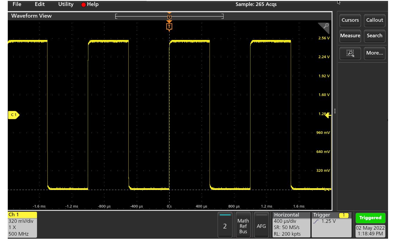
Check probe compensation
Procedure to check the probe compensation.
Procedure
- Push Autoset button on the front-panel or tap File > Autoset from the menu bar. The screen displays a square wave. The levels should be approximately 0 V - 2.5 V and 1 kHz.
Check Aux In
Procedure to check the Aux In.
Procedure
- Connect probe compensation to Aux In.
- Tap File > Default Setup.
- Double-tap the trigger badge on the settings bar and set the trigger Source to Aux In.
- Set Trigger Level to 1 V.
- Tap Trigger on the settings bar and verify the oscilloscope is Triggering.
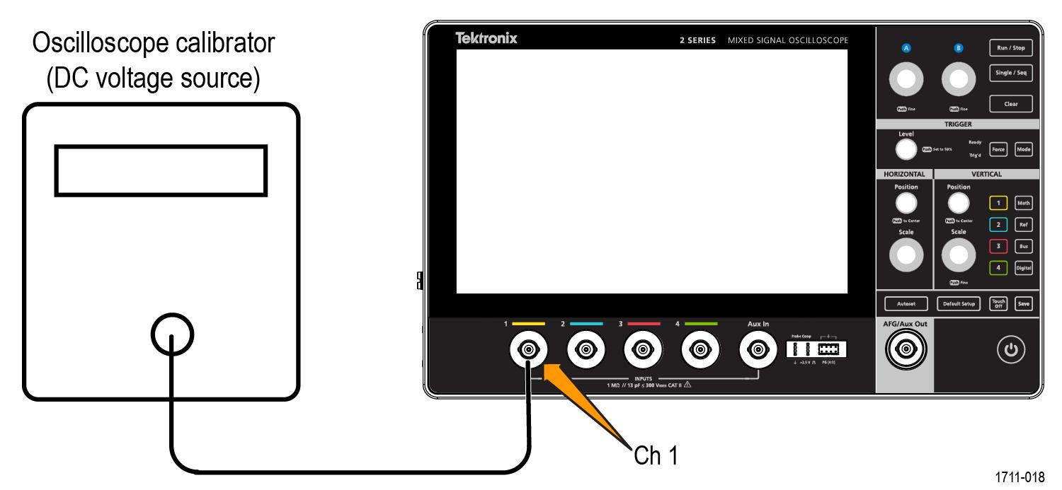
Check DC gain accuracy
Procedure to test the DC gain accuracy.
Procedure
| WARNING:Set the generator output to Off or 0 volts before connecting, disconnecting, and/or moving the test hookup during the performance of this procedure. The generator is capable of providing dangerous voltages. |
- Connect the oscilloscope to a calibrated DC voltage source. If you are using the Fluke 9500 calibrator, connect the calibrator head to the oscilloscope channel to test.
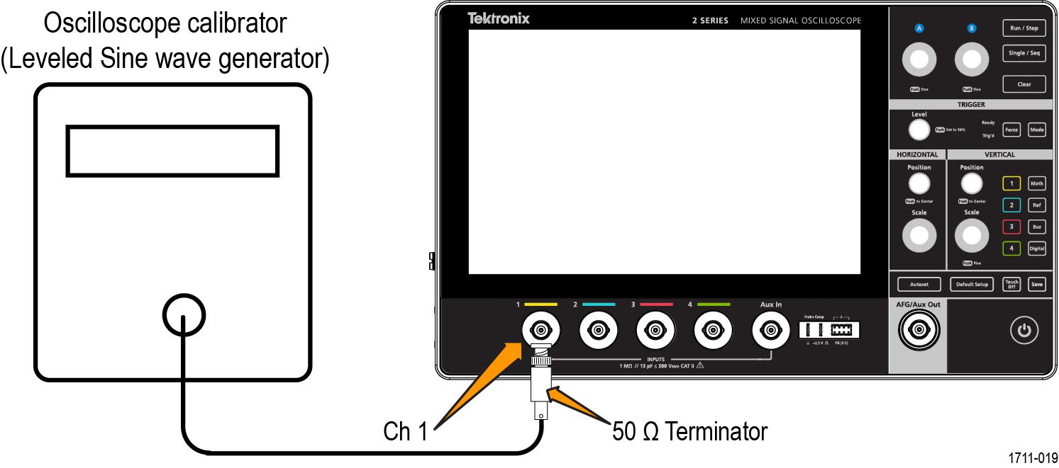
Check analog bandwidth
Procedure to check the bandwidth for each channel.
Procedure
| WARNING:Set the generator to off or 0 volts before connecting, disconnecting, and/or moving the test hookup during the performance of this procedure. The generator is capable of providing dangerous voltages. |
- Connect the output of the calibrated leveled sine wave generator to the 50 Ω terminator (Tektronix Part Number 011-0049-02) on Channel 1 as shown in the following illustration. If using the Fluke 9500 calibrator as the sine wave generator, connect the calibrator head to the 50 Ω terminator with the Fluke 9500 in 50 Ω output mode. Do not connect the Fluke 9500 calibrator head directly to the oscilloscope channel.
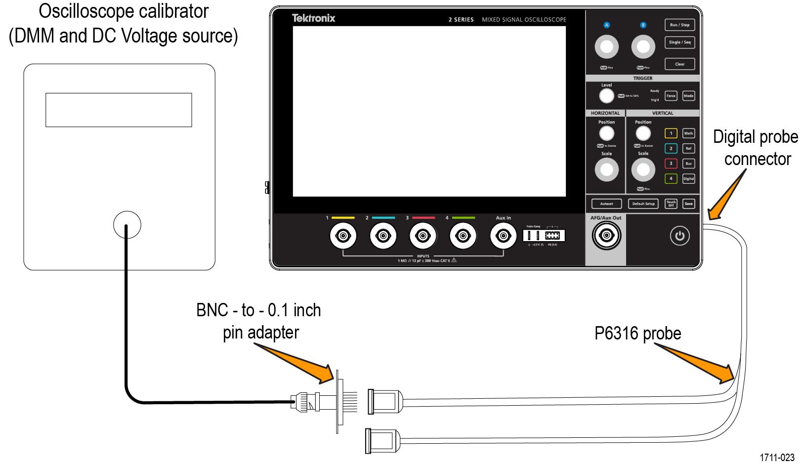
Check digital threshold accuracy with 2-MSO option
This procedure checks the threshold accuracy of the digital channels and is for models with the 2-MSO option only.
About this task
This procedure applies to digital channels D0 through D15, and to channel threshold values of 0 V and 4 V.
Procedure
- Connect the P6316 Group 1 pod to the DC voltage source to run this test. You will need a BNC-to-0.1 inch pin adapter to complete the connection. If using the Fluke 9500 calibrator as the DC voltage source, connect the calibrator head to the P6316 Group 1 pod. You will need a BNC-to-0.1 inch pin adapter to complete the connection.
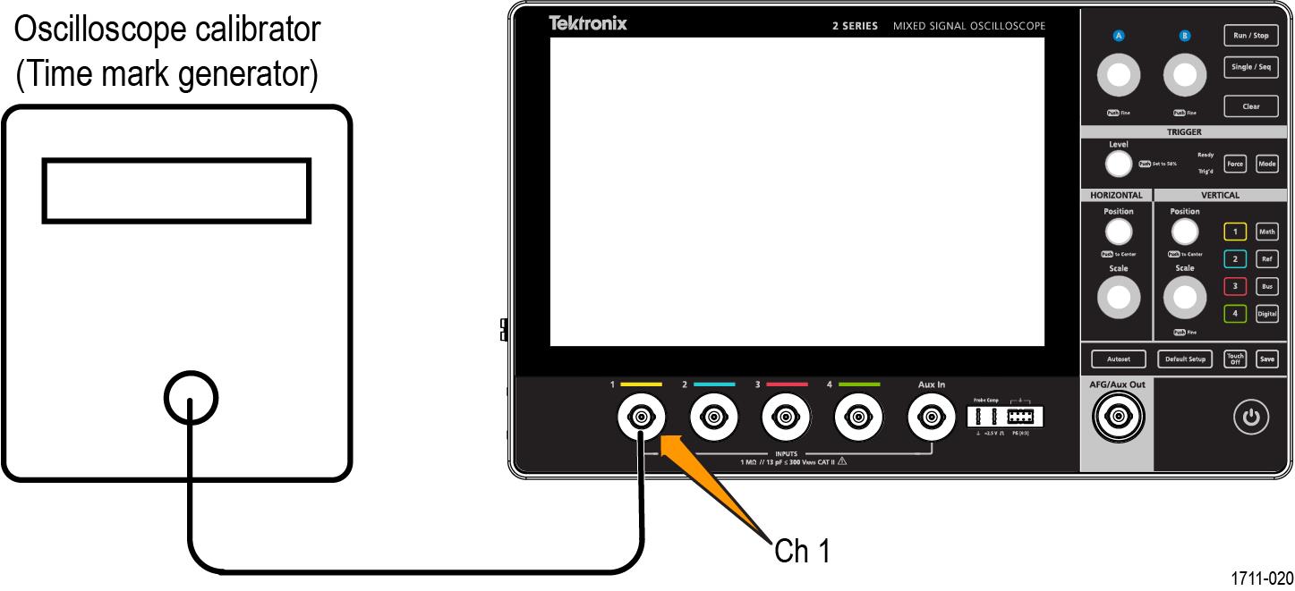
Check long term sample rate
This procedure checks the sample rate and delay time accuracy (time base).
Procedure
| WARNING:Set the generator to off or 0 volts before connecting, disconnecting, and/or moving the test hookup during the performance of this procedure. The generator is capable of providing dangerous voltages. |
- Connect the output of a time mark generator to the oscilloscope channel 1 input.
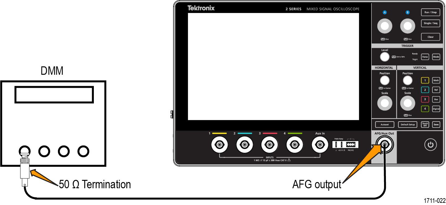
Check AFG DC offset accuracy
This procedure checks the AFG DC Offset Accuracy.
Procedure
- Connect the AFG output to the DMM through a 50 Ω termination.
Help us improve our technical documentation. Provide feedback on our TekTalk documentation forum.