연락처
텍트로닉스 담당자와 실시간 상담 6:00am-4:30pm PST에 이용 가능
전화 문의
9:00am-6:00PM KST에 이용 가능
다운로드
매뉴얼, 데이터 시트, 소프트웨어 등을 다운로드할 수 있습니다.
피드백
2-BP Battery Pack Instructions
This document describes the 2-BP battery pack and instructions for installing and using your battery pack with the 2 Series MSO.
이 매뉴얼은 다음에 적용됩니다.:
MSO22, MSO24, 2-BP, MSO22-EDU, MSO24-EDU
By downloading, you agree to the terms and conditions of the Manuals Download Agreement.
Manuals Download Agreement
ATTENTION: please read the following terms and conditions carefully before downloading any documents from this website. By downloading manuals from Tektronix' website, you agree to the following terms and conditions:
Manuals for Products That Are Currently Supported:
Tektronix hereby grants permission and license to owners of Tektronix instruments to download and reproduce the manuals on this website for their own internal or personal use. Manuals for currently supported products may not be reproduced for distribution to others unless specifically authorized in writing by Tektronix, Inc.
A Tektronix manual may have been revised to reflect changes made to the product during its manufacturing life. Thus, different versions of a manual may exist for any given product. Care should be taken to ensure that one obtains the proper manual version for a specific product serial number.
Manuals for Products That Are No Longer Supported:
Tektronix cannot provide manuals for measurement products that are no longer eligible for long term support. Tektronix hereby grants permission and license for others to reproduce and distribute copies of any Tektronix measurement product manual, including user manuals, operator's manuals, service manuals, and the like, that (a) have a Tektronix Part Number and (b) are for a measurement product that is no longer supported by Tektronix.
A Tektronix manual may be revised to reflect changes made to the product during its manufacturing life. Thus, different versions of a manual may exist for any given product. Care should be taken to ensure that one obtains the proper manual version for a specific product serial number.
This permission and license does not apply to any manual or other publication that is still available from Tektronix, or to any manual or other publication for a video production product or a color printer product.
Disclaimer:
Tektronix does not warrant the accuracy or completeness of the information, text, graphics, schematics, parts lists, or other material contained within any measurement product manual or other publication that is not supplied by Tektronix or that is produced or distributed in accordance with the permission and license set forth above.
Tektronix may make changes to the content of this website or to its products at any time without notice.
Limitation of Liability:
TEKTRONIX SHALL NOT BE LIABLE FOR ANY DAMAGES WHATSOEVER (INCLUDING, WITHOUT LIMITATION, ANY CONSEQUENTIAL OR INCIDENTAL DAMAGES, DAMAGES FOR LOSS OF PROFITS, BUSINESS INTERRUPTION, OR FOR INFRINGEMENT OF INTELLECTUAL PROPERTY) ARISING OUT OF THE USE OF ANY MEASUREMENT PRODUCT MANUAL OR OTHER PUBLICATION PRODUCED OR DISTRIBUTED IN ACCORDANCE WITH THE PERMISSION AND LICENSE SET FORTH ABOVE.
Read Online
Battery pack information
The battery pack allows you to perform measurements without relying on AC power. All 2 Series MSO instruments support the installation of the battery pack.
You can operate the instrument continuously for approximately three hours with one battery and six hours with two batteries in the battery pack. The instrument turns off automatically when the batteries run out of power. An on-screen icon and battery status menu indicates the remaining battery power.
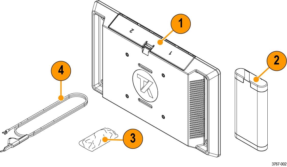
Parts list
| Item | Part Number | Description |
|---|---|---|
| 1 | 2-BP | 2 Series MSO Battery Pack with two battery slots; ordered separate from instrument purchase. |
| 2-BATPK | 2 Series MSO Battery Pack with two battery slots; option ordered with instrument purchase. | |
| 2 | TEKBAT-XX | Battery; lithium-ion, rechargeable, SMBUS, recessed terminals, UL, safety controlled |
| 3 | 211-1722-XX | Pack of 4 screws, M4X.7X12MM |
| 4 | 174-7369-XX | Ground cable, safety controlled |
Recommended installation tools
Use a screwdriver handle with No. 2 Phillips screw tip or a No. 2 Phillips screwdriver to install the battery pack onto your instrument.
Important safety information
This manual contains information and warnings that must be followed by the user for safe operation and to keep the product in a safe condition.
To safely perform service on this product, see the Service safety summary that follows the General safety summary.
General safety summary
Use the product only as specified. Review the following safety precautions to avoid injury and prevent damage to this product or any products connected to it. Carefully read all instructions. Retain these instructions for future reference.
This product shall be used in accordance with local and national codes.
For correct and safe operation of the product, it is essential that you follow generally accepted safety procedures in addition to the safety precautions specified in this manual.
The product is designed to be used by trained personnel only.
Only qualified personnel who are aware of the hazards involved should remove the cover for repair, maintenance, or adjustment.
Before use, always check the product with a known source to be sure it is operating correctly.
While using this product, you may need to access other parts of a larger system. Read the safety sections of the other component manuals for warnings and cautions related to operating the system.
When incorporating this equipment into a system, the safety of that system is the responsibility of the assembler of the system.
To avoid fire or personal injury
Do not operate without covers
Do not operate this product with covers or panels removed, or with the case open. Hazardous voltage exposure is possible.
Avoid exposed circuitry
Do not touch exposed connections and components when power is present.
Do not operate with suspected failures.
If you suspect that there is damage to this product, have it inspected by qualified service personnel.
Disable the product if it is damaged. Do not use the product if it is damaged or operates incorrectly. If in doubt about safety of the product, turn it off and disconnect the power cord. Clearly mark the product to prevent its further operation.
Before use, inspect voltage probes, test leads, and accessories for mechanical damage and replace when damaged. Do not use probes or test leads if they are damaged, if there is exposed metal, or if a wear indicator shows.
Examine the exterior of the product before you use it. Look for cracks or missing pieces.
Use only specified replacement parts.
Replace batteries properly
Replace batteries only with the specified type and rating.
Recharge batteries for the recommended charge cycle only.
Wear eye protection
Wear eye protection if exposure to high-intensity rays or laser radiation exists.
Do not operate in wet/damp conditions
Be aware that condensation may occur if a unit is moved from a cold to a warm environment.
Do not operate in an explosive atmosphere
Keep product surfaces clean and dry
Remove the input signals before you clean the product.
Provide proper ventilation.
Refer to the installation instructions in the manual for details on installing the product so it has proper ventilation.
Slots and openings are provided for ventilation and should never be covered or otherwise obstructed. Do not push objects into any of the openings.
Provide a safe working environment
Always place the product in a location convenient for viewing the display and indicators.
Avoid improper or prolonged use of keyboards, pointers, and button pads. Improper or prolonged keyboard or pointer use may result in serious injury.
Be sure your work area meets applicable ergonomic standards. Consult with an ergonomics professional to avoid stress injuries.
Use only the Tektronix rackmount hardware specified for this product.
Service safety summary
The Service safety summary section contains additional information required to safely perform service on the product. Only qualified personnel should perform service procedures. Read this Service safety summary and the General safety summary before performing any service procedures.
To avoid electric shock
Do not touch exposed connections.
Do not service alone
Do not perform internal service or adjustments of this product unless another person capable of rendering first aid and resuscitation is present.
Disconnect power
To avoid electric shock, switch off the product power and disconnect the power cord from the mains power before removing any covers or panels, or opening the case for servicing.
Use care when servicing with power on
Dangerous voltages or currents may exist in this product. Disconnect power, remove battery (if applicable), and disconnect test leads before removing protective panels, soldering, or replacing components.
Verify safety after repair
Always recheck ground continuity and mains dielectric strength after performing a repair.
Terms in this manual
These terms may appear in this manual:
 | WARNING:Warning statements identify conditions or practices that could result in injury or loss of life. |
| CAUTION:Caution statements identify conditions or practices that could result in damage to this product or other property. |
Terms on the product
These terms may appear on the product:
- DANGER indicates an injury hazard immediately accessible as you read the marking.
- WARNING indicates an injury hazard not immediately accessible as you read the marking.
- CAUTION indicates a hazard to property including the product.
Symbols on the product
 | When this symbol is marked on the product, be sure to consult the manual to find out the nature of the potential hazards and any actions which have to be taken to avoid them. (This symbol may also be used to refer the user to ratings in the manual.) |
The following symbols(s) may appear on the product.
 |  |  |  | |
 |  |  |
Compliance information
This section lists the safety and environmental standards with which the instrument complies. This product is intended for use by professionals and trained personnel only; it is not designed for use in households or by children.
Compliance questions may be directed to the following address:
Tektronix, Inc.
PO Box 500, MS 19-045
Beaverton, OR 97077, USA
Safety compliance
This section lists other safety compliance information.
Equipment type
Test and measuring equipment.
Pollution degree description
A measure of the contaminants that could occur in the environment around and within a product. Typically the internal environment inside a product is considered to be the same as the external. Products should be used only in the environment for which they are rated.
- Pollution Degree 1. No pollution or only dry, nonconductive pollution occurs. Products in this category are generally encapsulated, hermetically sealed, or located in clean rooms.
- Pollution Degree 2. Normally only dry, nonconductive pollution occurs. Occasionally a temporary conductivity that is caused by condensation must be expected. This location is a typical office/home environment. Temporary condensation occurs only when the product is out of service.
- Pollution Degree 3. Conductive pollution, or dry, nonconductive pollution that becomes conductive due to condensation. These are sheltered locations where neither temperature nor humidity is controlled. The area is protected from direct sunshine, rain, or direct wind.
- Pollution Degree 4. Pollution that generates persistent conductivity through conductive dust, rain, or snow. Typical outdoor locations.
Pollution degree rating
Pollution Degree 2 (as defined in IEC 61010-1)
Measurement and overvoltage category descriptions
Measurement terminals on this product may be rated for measuring mains voltages from one or more of the following categories (see specific ratings marked on the product and in the manual).
- Measurement Category II. For measurements performed on circuits directly connected to the low-voltage installation.
- Measurement Category III. For measurements performed in the building installation.
- Measurement Category IV. For measurements performed at the source of low-voltage installation.
| Note:Only mains power supply circuits have an overvoltage category rating. Only
measurement circuits have a measurement category rating. Other circuits within the
product do not have either rating. |
Mains overvoltage category rating
Overvoltage Category I (as defined in IEC 61010-1)
Instrument label accessibility
Installation of the battery pack covers the back instrument label. The label displays important information like the instrument model number, serial number, and CSA mark. To view label, uninstall the battery pack. The model and serial number is also accessible through the instrument user interface.
Environmental compliance
This section provides information about the environmental impact of the product.
Product end-of-life handling
Observe the following guidelines when recycling an instrument or component:
- Equipment recycling
- Production of this equipment required the extraction and use of natural resources. The equipment may contain substances that could be harmful to the environment or human health if improperly handled at the product’s end of life. To avoid release of such substances into the environment and to reduce the use of natural resources, we encourage you to recycle this product in an appropriate system that will ensure that most of the materials are reused or recycled appropriately.
 |
This symbol indicates that this product complies with the applicable European Union requirements according to Directives 2012/19/EU and 2006/66/EC on waste electrical and electronic equipment (WEEE) and batteries. For information about recycling options, check the Tektronix Web site (http://www.tek.com/productrecycling). |
- Battery recycling
- This product (2 Series MSO Battery Pack) is packed with a lithium-ion rechargeable battery pack. Please dispose of or recycle the battery pack at its end of life according to local government regulations.
- Lithium-ion batteries are subject to disposal and recycling regulations that vary by country and region. Always check and follow your applicable regulations before disposing of any battery. Contact Rechargeable Battery Recycling Corporation (www.rbrc.org) for U.S.A. and Canada, or your local battery recycling organization.
- Many countries prohibit the disposal of waste batteries in standard waste receptacles.
- Place only discharged batteries in a battery collection container. Use electrical tape or other approved covering over the battery connection points to prevent short circuits.
Transporting batteries
The small lithium-ion rechargeable battery that is packed with this product does not exceed a capacity of 100 Wh per battery or 20 Wh per component cell. Each battery type has been shown by the manufacturer to comply with the applicable requirements of the UN Manual of Tests and Criteria Part III, Subsection 38.3. Consult your carrier to determine which lithium battery transportation requirements are applicable to your configuration, including to its re-packaging and re-labeling, prior to reshipment of the product by any mode of transport.
Operating requirements
Use the instrument within the required operating temperature, power, altitude, and signal input voltage ranges to provide the most accurate measurements and safe instrument operation.
| Characteristic | Description |
|---|---|
| Temperature | Operating instrument: 0°C to +50°C (+32°F to 120°F), with 5 °C/minute maximum gradient, noncondensing (NC) |
| Operating with battery: 0 °C to 45 °C (+32 °F to 113 °F) | |
| For proper cooling, keep the rear of the instrument clear of obstructions for 2 inches (51 mm). | |
| Operating humidity | 5% to 90% relative humidity at temperatures up to +30°C, |
| 5% to 60% relative humidity at temperatures greater than +30°C and up to +50°C. | |
| Operating altitude | Up to 3000 meters (9842 feet) |
| Battery power | Requires 2-BATPK battery pack with 2 slots for batteries to be ordered with instrument or 2-BP battery pack with 2 slots for batteries to be ordered post instrument purchase |
| Supports up to 2 TEKBAT-XX Li-Ion rechargeable batteries. Operating time; Up to 3 hours single battery and up to 6 hours dual batteries. | |
| Tektronix recommends using the TEKCHG-XX external battery charger to charge the TEKBAT-XX batteries in ambient environments greater than +30°C. |
| Characteristic | Description |
|---|---|
| Power source voltage | 24 V DC |
| Power source current | 2.5 A |
Operating safely with battery power
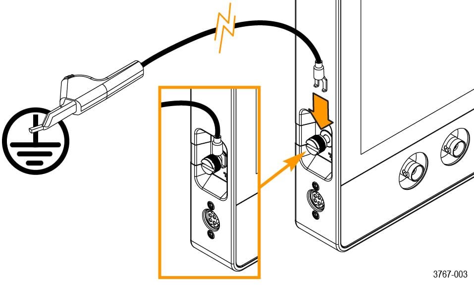
For safe operation, the instrument chassis should always remain at earth ground potential.
| WARNING:To avoid electric shock, always use the Tektronix-provided grounding cable when the oscilloscope is operating on battery power and not connected to the external power supply. The Tektronix-provided grounding cable is not for permanent usage. |
Without a connection between the chassis and earth ground, you may receive a shock from exposed metal on the chassis if you connect an input to a hazardous voltage (>30 VRMS, >42 Vpk). To protect yourself against possible shock, attach the Tektronix-provided grounding cable.
The grounding cable is necessary to provide protective bonding between the oscilloscope and a dedicated earthing terminal, in accordance with the NEC, CEC, and local codes. Consider having a qualified electrician to approve the installation.
The grounding cable shall be connected before powering on the oscilloscope and before attaching the probes to any circuit. Connect the grounding cable from the ground lug terminal on the side panel of the instrument to a dedicated earthing terminal. Make sure the teeth of the alligator clip makes good electrical contact and is secured against slipping.
The alligator clip on the grounding cable must be connected to a dedicated earthing terminal, an earthing terminal bar, or identified equipment grounding points (a rack cabinet for example). Make sure you have a good electrical connection to an appropriate grounding device that is identified with a Protective Earth symbol, or the word GROUND/GND, or the color green (green ground screw/conductor). If none of these are present, assume the connection is not earthed.
Always verify that the grounding cable is making good electrical contact by using an ohmmeter or continuity meter between the dedicated earthing terminal and the ground lug terminal on the side panel of the oscilloscope. Verify again anytime the oscilloscope has been left unattended.
Make sure the dedicated earthing terminal is located in close proximity to the circuit under test. Keep the grounding cable clear of heat sources and mechanical hazards such as; sharp edges, screw threads, moving parts, and closing doors/covers. Inspect the cable, insulation, and terminal ends for damage before use. Do not use a damaged grounding cable. Contact Tektronix for a replacement.
If you choose not to attach the grounding cable, you are not protected against electric shock if you connect the oscilloscope to a hazardous voltage. You can still use the oscilloscope if you do not connect a signal greater than 30 VRMS (42 Vpk) to the probe tip, the BNC connector center, or the common lead. Make sure all probe common leads are connected to the same voltage.
| WARNING:Hazardous voltages may exist in unexpected places due to faulty circuitry in the device under test. |
| CAUTION:When operating the instrument on battery power do not connect a grounded device, such as a printer or computer, to the oscilloscope unless the instrument grounding cable is connected to the earth ground. |
Battery pack installation
Install the battery pack to the back of your instrument.
Before you begin
| CAUTION:The battery interface connector is susceptible to Electrostatic Discharge (ESD). Use ESD precautions with installing or removing the battery pack. |
| WARNING:Before operating the instrument with the battery pack connected without an AC power source, always connect the ground cable. |
Procedure
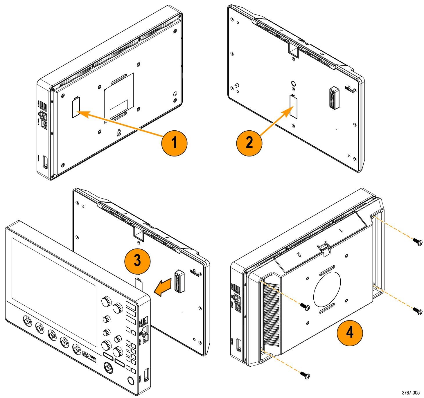
- Install the four provided screws into the corner screw mounts on the battery pack.CAUTION:The recommended torque is 3.6 N·m (32 inch-lbf). Failure to fully tighten the screws makes the battery pack more susceptible to fall damage.To remove the battery pack, reverse this procedure.
Rechargeable battery installation
The battery pack has 2 battery slots and supports hot swapping of the batteries during operation to extend the battery run time. The batteries are charged when the instrument is connected to an AC power source or charge each battery separately using the Tektronix external battery charger (TEKCHG-XX).
Procedure
Rechargeable battery removal
Procedure
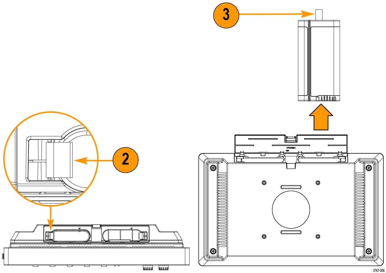
- Use your fingers to push on the door latch and open the door upward.
- Open the battery latch to release the battery from the slot.
- Use the battery pull tab to remove the battery from the slot.
- Close and latch the battery pack door.
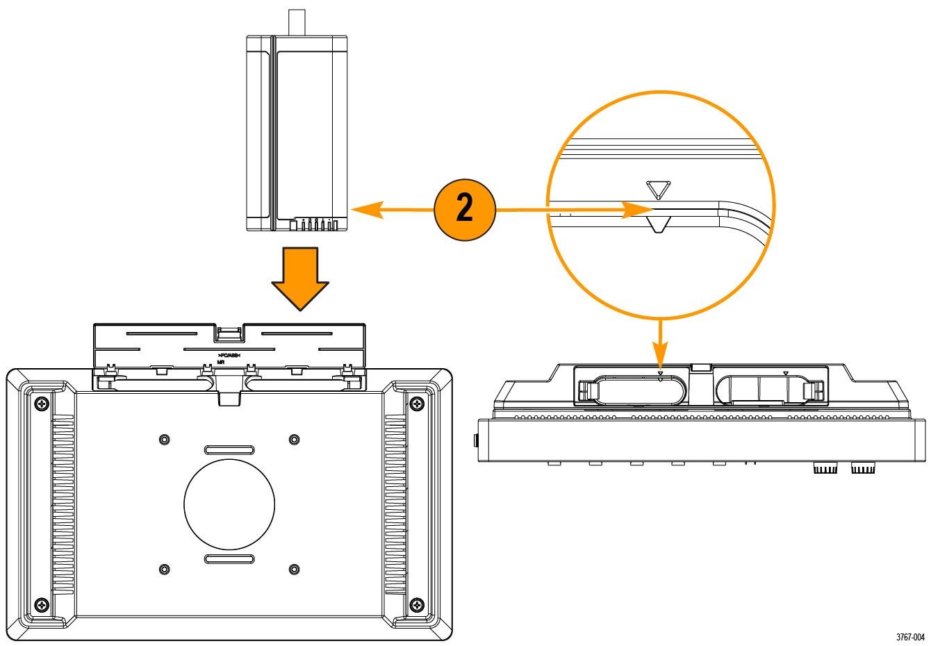
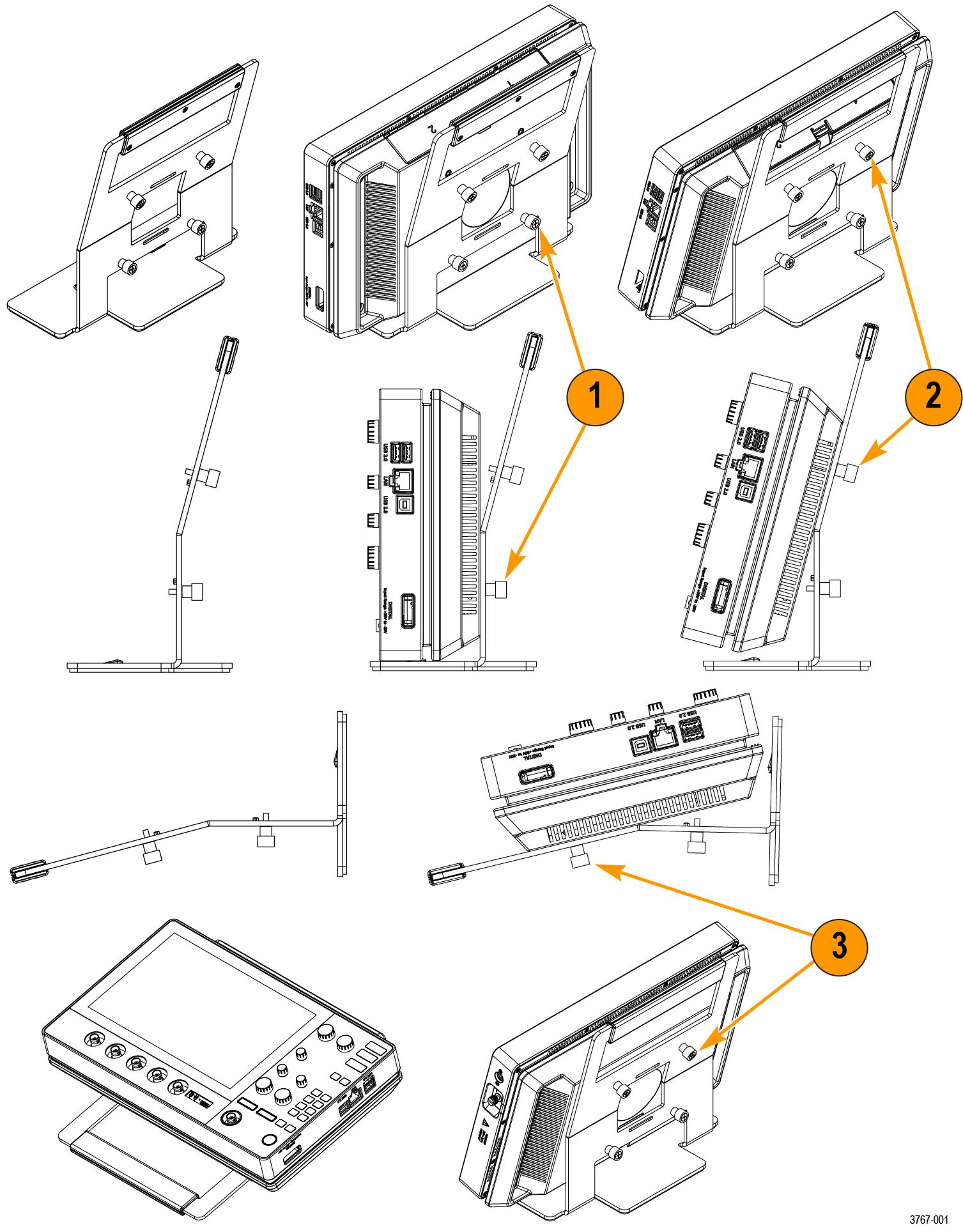
Instrument stand to battery pack installation
Mount your instrument to the provided stand in three configurations.
Before you begin
Align the stand with the four VESA screw mounts (closest to the label) on the back of the battery pack.
Procedure
Battery status
When the battery pack is installed and a battery is inserted, an icon and battery menu indicates the battery status.
The battery icon is displayed in the upper right corner of the screen. Double tapping the icon opens the battery menu. The battery menu indicates whether a battery has been inserted in slot 1 or 2, the battery serial number, a remaining charge percentage, and the battery time to full or empty.
A safety warning message automatically displays in the battery menu when an instrument is turned on with battery power only or when the power cord is removed from an instrument operating on battery power. You must tap the safety warning acknowledgement button to close the battery menu.
The following table and images describe the different icon states, Time to full, and Time to empty.

| Item | Description |
|---|---|
| 1 | The battery icon displays a power cord when connected to an AC power source. This indicates that the battery is charging in the battery pack. |
| 2 | The battery icon and a warning symbol when operating on a battery power alone. |
| 3 | The battery icon turns red when less than ten percent of the battery charge is remaining. |
| 4 | Time to full displays the time it takes for the battery fully charge when connected to an AC power source. |
| 5 | Time to empty displays the remaining time until the battery is empty. It is only displayed when operating on battery power alone. |
When the batteries in the 2-BP battery pack on your instrument have a low battery charge and the power cord is not connected, the power button will blink twice and then your instrument will turn off.
When two batteries are inserted into the 2-BP battery pack, the battery with the lowest battery life will begin charging first. The battery with the higher battery life displays a long Time to Full when it is not actively charging. The two batteries actively charge at the same rate when they reach a similar battery life. When both batteries are actively charging the Time to Full display accurately.
Help us improve our technical documentation. Provide feedback on our TekTalk documentation forum.