
연락처
텍트로닉스 담당자와 실시간 상담 6:00am-4:30pm PST에 이용 가능
전화
전화 문의
9:00am-6:00PM KST에 이용 가능
다운로드
매뉴얼, 데이터 시트, 소프트웨어 등을 다운로드할 수 있습니다.
피드백
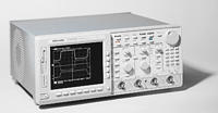
Digital Storage Oscilloscopes
TDS694C • TDS684C
이 데이터 시트의 제품은 텍트로닉스에서 더 이상 판매하지 않습니다.
리퍼브 테스트 장비에 대한 Tektronix Encore를 확인하십시오.
이러한 제품에 대한 지원 및 보증 상태를 살펴보십시오.
Features & Benefits
- 3 GHz and 1 GHz Bandwidths to Work with the Fastest Signals in Today's Digital Designs
- 10 GS/s and 5 GS/s Sample Rates on all Channels Simultaneously for Full Bandwidth Single-shot Capture
- Waveform Math and Advanced Waveform DSP
- Waveform Pass/Fail Template Testing
- Color Display
- RS-232, Centronics and GPIB Interfaces Included Standard
- Record Length to 120,000 Points/Channel*1
- Timebase Accuracy to 10 ppm, Time Interval Measurement Accuracy to ±15 ps (TDS694C)
- Trigger Jitter 8 psRMS (Typical)
- 1% Vertical Accuracy (TDS694C)
- 100 ps Peak Detect (TDS694C Only)
Applications
- Validation and Characterization of High Speed Digital Designs
- Verify Simulation Performance with Real Measurements
- Ensure that Desired Design Margins Exist
- Jitter Measurements on High-speed Data, Phase-locked Loops and Spread-spectrum Clock Circuits
- Capture Glitches, Cross-talk, Setup/Hold Violations
- Telecommunications/Data Communications Design
- Characterize Rise Times, Overshoot, Channel-to-channel Timing
- Verify and Test High-speed Serial Data Streams
- High-energy Physics
- Transient Event Capture
*1 TDS694C with long record length option (1 M) only. 15,000 points/channel maximum on TDS684C.
Whether you are working on next generation microprocessor designs, high-speed data communications equipment or in high-energy physics research, the TDS694C captures your fastest signals with the best fidelity and resolution available. Its 3 GHz bandwidth preserves your waveform's fast rising edges and accurately shows signal details. With 10 GS/s digitizing rate simultaneously on all four channels and a high-stability timebase, the TDS694C makes your critical timing measurements with the highest resolution and accuracy - even channel-to-channel measurements made in a single acquisition.
The TDS600C oscilloscopes incorporate all the advanced trigger features you expect in a high performance oscilloscope: triggering on Glitches, Slew Rate violations, Setup-and-hold Time violations, Timeouts, Logic Patterns and States on four channels. For applications where sophisticated multichannel debugging is required, the TDS694C can be configured for cross triggering with a Tektronix TLA700 Logic Analyzer.
The TDS600C oscilloscopes give you the total solution to your digital design characterization and debugging needs. Now you have the tool you need to verify design margins, characterize setup-and-hold times and measure clock-to-data skew on the fastest digital designs. The TDS694C's companion probe, the P6249, offers small size to reliably contact your high-density boards with their fine-pitch, hard to reach components. The P6249 has short ground connection to give the maximum system bandwidth and preserve the details of your signals.
The TDS600C offers 29 automatic measurements, with measurement statistics, to make your design verification and characterization job much faster and easier. Available Java-based application packages for jitter analysis, disk drive measurements and processor specification measurements provide customized measurements and analysis capability. The TDS600C gives you the performance and features you need to get your job done faster and more thoroughly.
Characteristics
Time Base System
Time Bases - Main and delayed
Time/div Range -
TDS684C: 200 ps/div to 10 s/div
TDS694C: 100 ps/div to 10 s/div
Time Base Accuracy -
TDS684C: Over any interval >1 ms ±100 ppm
TDS694C: Over any interval >1 ms ±10 ppm
Time Interval Measurement Accuracy -
TDS684C: ±[(0.2/sample rate) + (100 ppm x |reading|)] single shot. (approximately 50 ps at a rate of 5 GS/s)
TDS694C: ±[(0.15/sample rate) + (10 ppm x |reading|)] single shot. (approximately 15 ps at a rate of 10 GS/s)
Record Length per Channel -
TDS684C: 500 to 15,000 pts.
TDS694C: 500 to 30,000 pts. (optional: 120,000 pts.)
Trigger Jitter - 8 psRMS (typical)
Pre-trigger Position - 0% to 100% of record
Channel-to-channel Deskew Range - ±25 ns
Vertical System
Vertical Resolution - 8-bit (>11-bit with averaging)
Vertical Sensitivity -
TDS684C: 1 mV/div to 10 V/div
TDS694C: 10 mV/div to 1 V/div
Floppy Disk Drive - Store reference waveforms, setups and image files on 3.5 in. 1.44 MB or 720 K Microsoft DOS-format floppy disk
Maximum Input Voltage - 300 V CAT II; ±400 V peak. Derate at 20 dB/decade above 1 MHz. Except TDS694C: 5 VRMS
DC Gain Accuracy -
TDS684C: ±1.5%
TDS694C: ±1.0%
Position Range - ±5 divs
Offset -
TDS684C:
±1 V from 1 to 99.5 mV/div
±10 V from 100 mV to 995 mV/div
±100 V from 1 V to 10 V/div
TDS694C:
±0.5 V from 10 to 50 mV/div
±0.25 V from 50.5 to 100 mV/div
±5 V from 101 to 500 mV/div
±2.5 V from 505 mV to 1 V/div
Bandwidth Selections -
TDS684C: 20 MHz, 250 MHz and full
TDS694C: Full only
Input Impedance Selections -
TDS684C: 1 megohm in parallel with 10 pF, or 50 ohm (AC and DC coupling)
TDS694C: 50 ohm (DC coupled)
Input Coupling -
TDS684C: AC, DC or GND
TDS694C: DC or GND
AC Coupled Low Frequency Limit (except TDS694C) -
<10 Hz when AC, 1 megohm coupled. <200 kHz when AC, 50 ohm coupled.
Channel Isolation - >100:1 at 100 MHz and >30:1 at BW for any two channels having equal V/div settings
Acquisition Modes
Peak Detect - High-frequency and random glitch capture. Captures glitches of 1 ns using acquisition hardware at all real-time sampling rates. TDS694C captures glitches of 100 ps.
Sample - Sample data only
Envelope - Max/min values acquired over one or more acquisitions
Average - Waveform data from 2 to 10,000 waveforms (selectable) is averaged
Single Sequence - Use RUN/STOP button to capture a single triggered acquisition at a time, which may be automatically saved to NVRAM with AutoSave
Triggering System and Trigger Types
EDGE (main and delayed) - Conventional level-driven trigger. Positive or negative slope on any channel or rear panel auxiliary input. Coupling selections: DC, AC, noise reject, HF reject, LF reject.
LOGIC (main) -
PATTERN: Specifies a logical combination (AND, OR, NAND, NOR) of the four input channels (high, low, don't care). Trigger when pattern stays true or false for a specified time.
STATE: Any logical pattern of channels 1, 2 and 3 plus a clock edge on channel 4. Triggerable on rising or falling clock edge.
SETUP/HOLD: Trigger on violations of both setup time and hold time between clock and data which are on two input channels.
PULSE (main) -
GLITCH: Trigger on or reject glitches of positive, negative or either polarity. Minimum glitch width is 1.0 ns with 200 ps resolution.
RUNT: Trigger on a pulse that crosses one threshold but fails to cross a second threshold before crossing the first again.
WIDTH: Trigger on width of positive or negative pulse either within or out of selectable time limits (1 ns to 1 s).
SLEW RATE: Trigger on pulse edge rates that are either faster or slower than a set rate. Edges can be rising, falling or either.
TIMEOUT: Trigger on an event which remains high, low or either, for a specified time period, selectable from 1 ns to 1 s, with 200 ps resolution.
TLA Cross Trigger (TDS694C only) - Utilize a TLA700 logic analyzer to detect a multichannel event, then trigger the TDS694C. The trigger points on the TLA and TDS will be aligned in time.
VIDEO (optional; not available in TDS694C) -
Trigger on a particular line of individual, odd/even or all fields.
Trigger on a specific pixel of a line by using the video trigger with delay by events.
Choose positive or negative horizontal sync polarity.
525/NTSC: Choose monochrome or color (studio-quality NTSC) sync formats
625/PAL: Choose color or monochrome (studio-quality PAL) sync formats
HDTV: Choose from 1125/60, 1050/60, 1250/50 and 787.5/60 HDTV formats
Trigger Bandwidth (edge type) -
TDS684C: 1 GHz
TDS694C: 3 GHz
Main Trigger Modes - Auto, normal, single
Delayed Trigger - Delay by time, events, or events and time
Delay by Time Range - 16 ns to 250 s
Delay by Events Range - 2 to 9,999,999 events
External Trigger Input -
Input impedance: ≥1.5 kilohm
Max. input voltage: ±20 V (DC + peak AC)
Display Characteristics
Waveform Style - Dots, vectors, variable persistence from 32 ms to 10 s, infinite persistence and intensified samples
Color - Standard palettes and user-definable color for waveforms, text, graticules and cursors. Measurement text and cursor colors matched to waveform. Waveform collision areas highlighted with different color. Statistical waveform distribution shown with color grading through variable persistence.
Color Grading - With variable persistence selected, historical timing information is represented by temporal or spectral color scheme
Graticules - Full, grid, cross-hair, frame and NTSC and PAL (with video trigger option)
Format - YT and XY
Resolution - 640 horizontal by 480 vertical displayed pixels (VGA)
Color CRT Monitor - 7 in. diagonal NuColorTM liquid crystal full-color shutter, 256 levels
Measurement System
Automatic Waveform Measurements - Period, frequency, +width, -width, rise time, fall time, +duty cycle, -duty cycle, delay, phase, burst width, high, low, max, min, peak to peak, amplitude, +overshoot, -overshoot, mean, cycle mean, RMS, cycle RMS, area, cycle area, extinction ratio (ratio, dB, %) and mean optical power. Continuous update of up to four measurements on any combination of waveforms.
Measurement Statistics - Display minimum and maximum or mean and standard deviation on any displayed single-waveform measurements.
Thresholds - Settable in percentage or voltage.
Gating - Any region of the waveform may be isolated for measurement using vertical bars.
Snapshot - Performs all measurements on any one waveform showing results from one instant in time.
Cursor Measurements - Absolute, delta: Volts, time, frequency, and NTSC IRE and line number (with video trigger option).
Cursor Types - Horizontal bars (volts), vertical bars (time); operated independently or in tracking mode.
Histogram Measurements - Mean, median, standard deviation, hits, waveform count, peak hits, peak-to-peak, % mean ±1, 2 and 3 standard deviations.
Waveform Processing
Waveform Functions - Interpolation (sin(x)/x or linear), average, envelope, auto setup
Advanced Waveform Functions - FFT, integration, differentiation, waveform (math or acquired) limit testing
Arithmetic Operators - Add, subtract, multiply, divide, invert
Autoset - Single-button, automatic setup on selected input signal for vertical, horizontal and trigger systems
Waveform Limit Testing - Compares incoming or math waveform to a reference waveform's upper and lower limits
Waveform Histograms - Both vertical and horizontal histograms, with periodically updated measurements, allow statistical distributions to be analyzed over any region of the signal
Power Requirements
Line Voltage Range - 100 to 240 VRMS
Line Frequency - 45 to 440 Hz
Power Consumption -
TDS654C/684C: 300 W max
TDS694C: 450 W max
Environmental and Safety
Temperature -
TDS684C:
Operating: +4°C to +45°C (floppy not used), +10°C to +45°C (floppy in use)
Nonoperating: -22°C to +60°C
TDS694C:
Operating: +5°C to +40°C (floppy not used), +10°C to +40°C (floppy in use)
Nonoperating: -22°C to +60°C
Humidity - Operating: 20% to 80% RH at or below +32°C
Altitude -
Operating: 15,000 ft. (hard disk not used), 10,000 ft. (hard disk in use)
Nonoperating: 40,000 ft.
Electromagnetic Compatibility - 89/336/EEC
Safety - UL 3111-1, CSA1010.1, EN61010-1, IEC61010-1
Physical Characteristics
|
Dimensions |
mm |
in. |
|---|---|---|
|
Weight |
kg |
lbs. |
|
Height with feet |
193 |
7.6 |
|
Height without feet |
178 |
7 |
|
Width with handle |
445 |
17.5 |
|
Depth with front cover installed |
434 |
17.1 |
|
Net approximately |
14.1 |
31 |
|
Shipping weight approximately |
24.0 |
53 |
-

Product(s) are manufactured in ISO registered facilities. Product(s) complies with IEEE Standard 488.1-1987, RS-232-C, and with Tektronix Standard Codes and Formats. 55W-10066-9

