
연락처
텍트로닉스 담당자와 실시간 상담 6:00am-4:30pm PST에 이용 가능
전화
전화 문의
9:00am-6:00PM KST에 이용 가능
다운로드
매뉴얼, 데이터 시트, 소프트웨어 등을 다운로드할 수 있습니다.
피드백
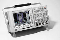
TDS3000 Series Digital Phosphor Oscilloscopes - Datasheet
TDS3000 Datasheet. (Product has been replaced by TDS3000C.)
이 데이터 시트의 제품은 텍트로닉스에서 더 이상 판매하지 않습니다.
리퍼브 테스트 장비에 대한 Tektronix Encore를 확인하십시오.
이러한 제품에 대한 지원 및 보증 상태를 살펴보십시오.
Features & Benefits
- 500 MHz, 300 MHz, and 100 MHz Bandwidths
- Sample Rates up to 5 GS/s
- 2 or 4 Channels
- Full VGA Color LCD on all Models
- Built-in Floppy Disk Drive For Easy Storage and Documentation
- 21 Automatic Measurements
- Centronics Port Standard on all Models for Quick, Convenient Hardcopies
- 9-bit Vertical Resolution
- Multi-Language User Interface
- QuickMenu User Interface Mode for Quick, Easy Operation
- Optional Modules for RS-232, GPIB, LAN or VGA Communication Ports
- Advanced Triggers, such as, Glitch, Width, and Logic Standard on 4 Channel Models
- Telecommunications Mask Testing (TMT)
- Fast Fourier Transform (FFT) for Frequency and Harmonic Analysis Standard on 4 Channel Models
- Extended Video Application Module
- Support for Active Probes, Differential Probes, and Current Probes that Provide Automatic Scaling and Units
Applications
- Telecommunications Manufacturing (Telecom Mask Test Application Module for Pass/Fail Compliance of ITU-T G.703 and ANSI T1.102 [Up to STS-1 Rates] Standards)
- Digital Design and Debug
- Video Design and Service (Video Application Modules Offer Line Count, HDTV and Custom Video Trigger, Video Display Graticules, SDI to Analog Video Conversion with Composite and Component Outputs, Video Picture Identification and Vectorscope)
- Industrial Electronic Design
- Power Supply Design
- Connected Instrumentation (10Base-T LAN, GPIB and VGA Modules with RS-232)
- Highly Mobile Environments (Optional Battery Pack for Convenient Use in the Field or Away from the Bench)
The TDS3000 Series of Digital Phosphor Oscilloscopes
The TDS3000 oscilloscopes are the lowest priced, most portable Digital Phosphor Oscilloscopes (DPOs). Now every design engineer and technician can take advantage of the tremendous benefits of DPOs. DPOs deliver a new level of insight that makes dealing with complex signals simple. DPOs display, store, and analyze, in real-time three dimensions of signal information: amplitude, time, and distribution of amplitude over time.
Benefits of DPO
DPOs have an intensity graded color display that provides information about the frequency of occurrence of signal amplitudes and widths. This helps the user locate and characterize waveform anomalies that can be elusive on traditional Digital Storage Oscilloscopes. The fast update rate of DPOs also makes it easier to capture and display infrequent waveforms or waveform variations.
Quick to Learn and Quick to Use
The TDS3000 Series graphical user interface offers a new operating mode called QuickMenu. This quick access user interface makes the main oscilloscope controls accessible with a push of a single button. Included with every scope is an On-Line Tour disk that runs in the oscilloscope. This disk gives an overview of the product's operation and capabilities.
Flexible Features for Every Application
The portable form factor allows the instrument to go wherever it is needed. The Communication and Application Modules enable the instrument to be configured for specific applications or upgraded without returning it to the manufacturer. The TekProbe® Level II interface provides power to a range of application specific accessories.
Application Modules
With the application module concept, the TDS3000 Series can be easily adapted to the needs of the user. These modules are easily installed by the user. At power on the scope indicates which modules are installed. Currently, there are five application modules available for the TDS3000 Series - a telecommunications mask test module, an FFT module, an advanced trigger module, a 601 digital video module and an extended video module. In addition, there are three communication modules available - a 10Base-T LAN/RS-232 module, a GPIB/RS-232 module and a VGA/RS-232 module. Centronics port is standard.
TDS3TMT - Telecommunications Mask Testing Module
When this module is installed in the TDS3000 Series scope, the TDS3000 DPO becomes a Pass/Fail test instrument for telecommunications standard compliance testing.
- ITU-T G.703 (DS0, DS1, E1, Clk Interface, DS2, E2, E3, and DS3 rates) standards supported
- ANSI T1.102 (DS1, DS1A, DS1C, DS2, DS3, and STS-1 rates) standards supported
- Custom mask editing also available using WaveStar™ software for oscilloscopes V2.3
- Properly terminate your device under test with Communication Signal Adapters
- Use TDS3GM (GPIB) or the NEW TDS3EM (LAN) communication modules to program the TDS3000 for automated testing
Typical Application of TMT Module
When testing network line cards in manufacturing, one of the most important considerations is throughput! The combination of DPO waveform throughput and hardware assisted mask testing results in breakthrough test speeds for mask testing on single and multiple channel devices.
TDS3000 DPO provides breakthrough test speeds for Telecommunications line cards testing.
TDS3FFT - FFT Module
When this module is installed in the TDS3000 Series scope, the scope becomes an excellent troubleshooting aid for:
- Testing impulse response of filters and systems
- Measuring harmonic content and distortions in systems
- Identifying and locating noise and interference sources
- Analyzing vibration
- Analyzing harmonics in 50 and 60 Hz power lines
The TDS3FFT application module provides the following features:
- FFT Windows; Four FFT windows (Rectangular, Hamming, Hanning and Blackman-Harris) let you match the optimum window to the signal you are analyzing
- Analyze repetitive, single-shot and stored waveforms: An FFT waveform on any actively-acquired signal, last acquired signal or signal stored in the reference memory can be displayed
- The FFT vertical graticule can be set to either dB or linear RMS
- The time signals and FFT waveforms can be shown on the display at the same time. This helps in the quick analysis of circuit or system problems.

TDS3000 DPO answers today's power measurement problems.
Typical Application for the FFT Module
In the design or analysis of power supplies, it is important to check the harmonics in the power supply's load current. The following figure shows the harmonic analysis of a 250 watt class D power supply. Using the scope's cursors, you can measure the frequency and magnitude of the individual frequency components.
TDS3TRG - Advanced Trigger Module
When this module is installed in the TDS3000 Series scope, an advanced trigger menu is added to the scope with the appropriate logic and pulse triggering capability.
Logic Trigger Features
Logic triggering is extremely useful in the troubleshooting of digital circuits. The oscilloscope is triggered when two signals meet a Boolean trigger condition. This module provides pattern and state logic trigger modes.
Pattern Trigger -
Pattern triggering triggers the oscilloscope when two signals become logically true or false. Basically, the pattern-triggering feature triggers the oscilloscope from the output of a two-input AND, OR, NAND or NOR logic gate. You can specify time constraints and signal threshold levels as part of the triggering condition. The trigger is useful for digital logic troubleshooting.
State Trigger -
State triggering triggers the oscilloscope when a state signal is true or false at the time a clock signal transition is true. This trigger is useful for troubleshooting digital logic synchronous state machines.
Pulse Trigger Features
Pulse triggering triggers the oscilloscope when a signal meets a timing or threshold condition. The advanced trigger module provides three pulse trigger modes: pulse width, runt pulse and slew rate.
Pulse Width (or Glitch) -
Pulse Width triggering triggers the oscilloscope when a signal pulse width is less than, greater than, equal to or not equal to a specified pulse width. this trigger is useful for digital logic troubleshooting.
Runt Pulse -
Runt Pulse triggering triggers the oscilloscope when a signal pulse is less than a specified threshold level. You can also specify runt pulse-width parameters. This trigger is useful for troubleshooting bus-contention problems.
Slew Rate -
Slew Rate triggering triggers the oscilloscope when a signal's slew rate (rise or fall time) is less than, greater than, equal to or not equal to a specified slew rate. This trigger is useful for troubleshooting digital bus transceivers, transmission lines and op-amp circuits.
TDS3VID - Extended Video Module
All TDS3000 Series oscilloscopes come standard with NTSC, PAL and SECAM (All Fields or All Lines) triggering capability. The TDS3VID application module extends this basic video triggering by adding the following features.
Video QuickMenu -
This Video QuickMenu function allows you to display a bottom and side menu that contains video functions useful for displaying and measuring broadcast standard waveforms, including trigger source, when to trigger, video graticule and video autoset.
Video Autoset -
The autoset function automatically adjusts the vertical, horizontal and video trigger settings to display a video waveform triggered on all lines and fields. You can then manually adjust controls to optimize the display. This function is available in the Video QuickMenu and in the Acquire menu.
Custom Video -
Using the custom video function allows you to specify custom horizontal scan rates in order to trigger on non-broadcast video waveforms, such as those used by computer monitors and medical equipment displays. This following figure shows the TDS3000 scope triggering on a scan rate of 26.2 kHz.
Line Count Trigger -
Sometimes it is necessary to view a single line of the video waveform. For example, the programming information in the NTSC signal is sometimes found on Line 20. Line Count triggering allows you to trigger on any particular line by scrolling through the line numbers and selecting the one you want.
Field Holdoff -
The field holdoff function provides the capability to specify a number of fields to wait before re-enabling triggering. This allows you to trigger on a single filed (e.g. field 1 or field 3 of NTSC) instead of both field 1 and field 3.
Video Graticules -
The video graticule function provides the capability for the user to change the standard oscilloscope graticule to either IRE or mV depending on the signal format. Video graticules make it easier to measure and analyze video waveforms.

DPO technology brings out vivid video waveform detail on the IRE graticule.
Characteristics
TDS3000 Series Electrical Characteristics
| TDS3012 | TDS3032 | TDS3052 | TDS3014 | TDS3034 | TDS3054 |
|---|---|---|---|---|---|---|
Bandwidth | 100 MHz | 300 MHz | 500 MHz | 100 MHz | 300 MHz | 500 MHz |
Channels | 2 | 2 | 2 | 4 | 4 | 4 |
Sample Rate on Each Channel | 1.25 GS/s | 2.5 GS/s | 5 GS/s | 1.25 GS/s | 2.5 GS/s | 5 GS/s |
Maximum Record Length | 10K points on all models | |||||
Vertical Resolution | 9–bits on all models | |||||
Vertical Sensitivity (/div) | 1 mV-10 V on all models | |||||
Vertical Accuracy | ±2% on all models*1 | |||||
Max Input Voltage (1 megohm) | 150V RMS CAT I on all models | |||||
Position Range | ±5 div on all models | |||||
BW Limit | 20 MHz | 20, 150 MHz | 20, 150 MHz | 20 MHz | 20, 150 MHz | 20, 150 MHz |
Input Coupling | AC, DC, GND on all models | |||||
Input Impedance Selections | 1 megaohm in parallel with 13 pF, or 50 ohm | |||||
Time Base: |
| |||||
Range (/div) | 4 ns - 10 s/div | 2 ns - 10 s/div | 1 ns - 10 s/div | 4 ns - 10 s/div | 2 ns - 10 s/div | 1 ns - 10 s/div |
Accuracy | 200 ppm | 200 ppm | 200 ppm | 200 ppm | 200 ppm | 200 ppm |
Display Monitor | Color LCD |
*1 Derated at 0.07%/°C for temperatures above +28°C and below +18°C.
Acquisition Modes
DPO - Captures and displays complex waveforms, random events, and subtle patterns in actual signal behavior. DPOs are able to provide 3 dimensions of signal information, in real-time; amplitude, time, and the distribution of amplitude over time.
Peak Detect - High frequency and random glitch capture. Captures glitches as narrow as 1 ns.
Sample - Sample data only.
Envelope - Max/Min values acquired over one or more acquisitions.
Average - Waveform data from 2 to 572 (selectable) acquisitions is averaged.
Single Sequence - Use SINGLE SEQUENCE button to capture a single triggered acquisition sequence at a time.
Trigger System
Main Trigger Modes - Auto (supports Roll Mode for 40 ms/div and slower), Normal.
B Trigger - Trigger after time or events.
Trigger After Time Range - 13.2 ns to 50 s.
External Trigger Input (available on TDS30X2 only) - >1 megaohm in parallel with 17 pF; Max input voltage is 150 VRMS.
Trigger Types
Edge - Conventional level-driven trigger. Positive or negative slope on any channel. Coupling selections: DC, noise reject, HF reject, LF reject.
Video - Trigger on all lines or individual line, odd/even or all fields, or analog HDTV formats (1080i, 1080p, 720p, 480p). See optional TDS3VID and TDS3SDI application modules for extended video triggering and measurement features.
Logic - (Standard on TDS30X4, must purchase TDS3TRG for TDS30X2)
PATTERN: Specifies AND, OR, NAND, NOR when true or false for a specific time.
STATE: Any logic state. Triggerable on rising or falling edge, of a clock.
Note: Logic triggers can only be used on combinations of 2 inputs.
Pulse - (Standard on TDS30X4, must purchase TDS3TRG for TDS30X2)
WIDTH (or GLITCH): Trigger on pulse width less than, greater than, equal to, or not equal to a selectable time limit ranging from 39.6 ns to 50s.
RUNT: Trigger on a pulse that crosses one threshold but fails to cross a second threshold before crossing the first again.
SLEW RATE: Trigger on pulse edge rates that are either faster or slower than a set rate. Edges can be rising, falling, or either.
Comm (must purchase TDS3TMT) - Provides isolated pulse triggering required to perform DS1/DS3 telecommunications mask testing per ANSI T1.102 standard.
Measurement System
Automatic Waveform Measurements - Period, Frequency, +Width, -Width, Rise Time, Fall Time, +Duty Cycle, -Duty Cycle, +Overshoot, -Overshoot, High, Low, Max, Min, Pk-Pk, Amplitude, Mean, Cycle Mean, RMS, Cycle RMS, Burst Width. Display any four measurements from any combination of waveforms.
Thresholds - Settable in percentage or voltage.
Gating - Measurements can be gated using the screen or vertical cursors.
Waveform Processing
Deskew - Channel to channel deskew ±10 ns may be manually entered for better timing measurements and more accurate math waveforms.
Arithmetic Operators - Add, Subtract, Multiply, Divide.
Autoset - Single-button, automatic setup on selected input signal for vertical, horizontal, and trigger systems.
Display Characteristics
Waveform Style - Dots, vectors, and variable persistence.
Graticules - Full, grid, cross-hair, frame, NTSC, PAL, SECAM, vectorscope 100% and 75% color bars (with optional TDS3VID and TDS3SDI video application modules).
Format - YT, XY and Gated XYZ (XY with Z-axis blanking available on TDS30X4 only).
I/O Interface
Hardcopy Port (standard) - Centronics-type parallel.
TDS3GM Communications Module -
GPIB (IEEE-488.2) Programmability: Full talk/listen modes; Control of all modes, settings, and measurements.
RS-232-C Interface Programmability: Full talk/listen modes; Control of all modes, settings, and measurements. Baud Rate up to 38,400. DB-9 male connector.
Programmer Manual: (071-0381-00)
TDS3VM Communications Module -
VGA: Monitor output for direct display on large VGA-equipped monitors. DB-15 female connector, 31.6 kHz sync rate, EIA RS-343A compliant.
RS-232-C Interface Programmability: same as TDS3GM
Programmer Manual: same as TDS3GM
TDS3EM Communications Module -
Ethernet Port: 10Base-T with RJ-45 connector. Provides local area network printing and programming interface.
RS-232-C Interface programmability: same as TDS3GM
Programmer Manual: same as TDS3GM
Note: Only one Communication Module may be installed at a time.
All Communication Modules include WaveStar™ Software for oscilloscopes 30-day, full-functioning product demo.
Hard Copy Capability
Graphics File Formats - Interleaf (.img), TIF, PCX (PC Paintbrush), BMP (Microsoft Windows), and Encapsulated Postscript (EPS).
Printer Formats - Bubblejet, DPU-3445, Thinkjet, Deskjet, Laserjet, Epson (9 and 24-pin).
Environmental and Safety
Temperature - +5 to +50° C (operating), -20 to +60° C (nonoperating).
Humidity - 20% to 80% RH below 32° C, derate to 30% RH at 45° C (operating), 5% to 90% RH below 41° C, derate to 30% RH at 60° C (nonoperating).
Altitude - ≤3,000 m (operating), ≤15,000 m (nonoperating)
Electromagnetic Compatibility - Meets or exceeds EN55011 Class A Radiated and Conducted Emissions; EN50082-1; FCC 47 CFR, Part 15, Subpart B, Class A; Australian EMC Framework; Russian GOST EMC regulations.
Safety - UL3111-1, CSA1010.1, EN61010-1, IEC61010-1
Physical Characteristics
Instrument | ||
|---|---|---|
Dimensions | mm | in. |
Width | 375.0 | 14.8 |
Height | 176.0 | 6.9 |
Depth | 149.0 | 5.9 |
Weight | kg | lbs. |
Instrument only | 3.2 | 7.0 |
w/battery | 5.2 | 11.5 |
Instrument Shipping Package | ||
Dimensions | mm | in. |
Width | 502.0 | 19.8 |
Height | 375.0 | 14.8 |
Depth | 369.0 | 14.5 |
Rackmount | ||
Dimensions | mm | in. |
Width | 484.0 | 19.0 |
Height | 178.0 | 7.0 |
Depth | 152.0 | 6.0 |

Product(s) are manufactured in ISO registered facilities.
3GW-23252-0

