
연락처
텍트로닉스 담당자와 실시간 상담 6:00am-4:30pm PST에 이용 가능
전화
전화 문의
9:00am-6:00PM KST에 이용 가능
다운로드
매뉴얼, 데이터 시트, 소프트웨어 등을 다운로드할 수 있습니다.
피드백
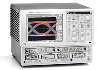
8200 시리즈 샘플링 오실로스코프
DSA8200
이 데이터 시트의 제품은 텍트로닉스에서 더 이상 판매하지 않습니다.
리퍼브 테스트 장비에 대한 Tektronix Encore를 확인하십시오.
이러한 제품에 대한 지원 및 보증 상태를 살펴보십시오.
특징과 장점
- DC ~ 70+ GHz*1의 대역폭 업계 최고의 시간축 정확도
- 지터
- 800fsRMS 표준
- 최대 8개의 신호 포착 채널을 갖춘 모듈형 아키텍처 첨단 지터, 잡음 및 BER 분석
- 1Gb/s ~ 60Gb/s의 고속 직렬 데이터 분석을 통해 아이 클로저의 정확한 원인 파악
- 지터 및 잡음의 분리를 통해 고도로 정 확한 BER 외삽과 아이 컨투어
- 고성능 TDR/TDT
- 진정한 차동 스텝 생성기 및 신호 포착
- 28ps 미만의 반사 상승 시간
- 최대 4개의 차동 쌍 (8채널)
- 고 충실도의 차동 및 단일 종단 프로빙
- 자동화된 표준 마스크 테스팅
- Sonet/SDH, Ethernet, OIF, Fibre Channel과 같은 통신 표준
- SATA, SAS, PCI Express, Rapid IO와 같은 컴퓨터 표준
- 100개 이상의 NRZ, 펄스 및 RZ 측정 기능을 갖춘 자동화된 측정 시스템 FrameScan신호 포착 모드
- 데이터 종속 장애의 분리
- 저 전력 신호 검사를 위한 신호 평균
- 4색으로 표시되는 가변 지속 파형 데이터베이스
- Microsoft Windows 2000 운영체제
어플리케이션
- 신호 무결성, 첨단 지터, 잡음 및
- BER 분석
- 차세대 디지털 설계 특성화
- 통신, 데이터 통신, SAN, 컴퓨터 및
- 고속 백플레인 설계의 특성화 및 제조
- 적합성 테스트
- PCB, 케이블, IC 패키지를 위한 TDR, 임피던스 특성화 및 누화 측정
*1 대역폭은 플러그인 모듈에 의해 결정되며, 향후에 더 빠른 속도의 모듈이 사용될 경우 70GHz를 초과할 수도 있습니다.
최첨단 신호 포착 시스템
CSA8200과 TDS8200 샘플링 오실로스코프 는 데이터 통신 및 통신 부품, 트랜시버 세부 조립품, 전송 시스템 분야의 연구, 설계 평가 및 제조 테스트, 컴퓨터 및 스토리지 기반의 고 속 전기 직렬 데이터, 반도체 테스트, TDR 기 반 임피던스 특성화를 비롯하여, 수십 GHZ의 대역폭을 요하는 기타 어플리케이션을 위한 포 괄적인 신호 포착 및 측정 장비입니다.
8200 시리즈는 시간 및 진폭 히스토그램, 마 스크 테스팅 및 통계 측정을 사용하여 단순한 원시 데이터가 아닌 측정 및 분석 결과를 생성 하며, RZ 및 NRZ 신호 모두에 대한 지터, 잡 음, 듀티 사이클, 오버슛, 언더슛, OMA, 소광 율(extinction ratio), Q 인자, 평균 광학력 및 증폭 측정을 포함한 통신 맞춤형 측정 집합을 제공합니다.
고속의 광/전기 통신 및 SDH/SONET, Ethernet, Fibre Channel 등과 같은 컴퓨터 표준에 대한 적합성 기반 마스크 테스팅 기능 을 갖추고 있는 8200 시리즈는 파형 데이터의 컬러/흑백 등급을 사용하여 신호 포착 및 분석 에 3차원의 샘플 밀도를 추가 분석하는 한편, 업계 최초로 가변 지속 데이터베이스를 통해 모 든 기능에 대한 정확한 데이터 및 측정 결과를 보존할 수 있으며 조정하는 동안 DUT에 대한 동적 업데이트 작업이 용이합니다. 8200 시리 즈에서는 매우 낮은 시간축 지터와 매우 빠른 신호 포착 속도가 결합되었을 뿐더러 각각 자 체 획득 파라미터와 디스플레이 창을 보유하고 있는 여러 시간대에서 데이터를 획득할 수 있 습니다. 이로써 획득 연산 및 파형 연산 기능 뿐만 아니라 데이터 평가를 위한 포괄적인 분석 기능이 가능하게 되어 히스토그램, 마스크테스팅, 통계와 같은 고급 프로세스를 수행할수 있게 됩니다.
8200 시리즈는 동시 사용이 가능한 네 개의 3D 데이터베이스를 통해 뛰어난 데이터 스토리지 유연성을 제공하고 데이터베이스는 정확한 데이터 누적을 통해 업계 최초의 가변 지속성을 제공합니다. 파형 데이터의 컬러 등급은신호 포착 및 분석에 3차원의 샘플 밀도를 추가하여 분석합니다.
CSA8200과 TDS8200 모델은 동일한 기능을공유합니다. 예를 들어 이러한 두 모델은 모두임의의 샘플링 모듈과 결합되어 구성될 수 있습니다.
강력한 지터, 잡음 및 BER 분석 기능
8000, 8000B 또는 8200 시리즈 오실로스코프에 80SJNB 첨단 지터, 잡음 및 BER 분석소프트웨어가 장착되면 포괄적인 직렬 데이터신호 손상 특성화 도구가 됩니다. 80SJNB는지터와 잡음의 분리를 통해 수평 및 수직 아이클로져의 근본 원인 파악 작업을 지원합니다. 지터와 잡음의 주요 구성 요소에 대한 독보적인 통찰력을 통해 고도로 정확하고 완전한 BER 외삽 및 아이 컨투어가 제공됩니다.
8000 시리즈의 모듈형 유연성에 지터, 잡음 및 BER 분석 기능이 결합되면(, 타협 없는 성능과) 타의 추종을 불허하는 신호 충실도가 실현되어, 1Gb/s에서 60Gb/s에 이르는 차세대 고속 직렬 데이터 설계 및 검증을 위한 이상적인솔루션을 얻게 됩니다.
모듈성 및 유연성
CSA8200 및 TDS8200 오실로스코프는 점점많은 전기/광 플러그인 모듈을 지원하고 있습니다. 이와 같은 모듈형 아키텍처를 통해 현재요구에 맞는 장비를 구성할 수 있으며 향후에도 모듈을 추가할 수 있어 장비에 대한 투자가보존됩니다. 차동 클럭 복구 모듈과 함께 이 장비를 사용하면 트리거가 존재하지 않는 상황에서도 차동 전기 신호를 포착하는 일이 가능합니다. 전기 모듈이 지원하는 대역폭은 최대70GHz에 달하고 차동 및 단일 종단 패시브 핸드 프로브는 최대 18GHz의 대역폭을 지원합니다. 널리 사용되고 있는 TekConnect프로빙 시스템 용 어댑터는 8200 시리즈 샘플링오실로스코프에 텍트로닉스의 첨단 고 임피던스 차동 및 단일 종단 프로브의 성능을 실현합니다.
또한 가장 대중적인 50Mb/s ~ 12.6Gb/s의데이터 전송률을 포괄하는 차동 전기 클럭 복구 모듈도 지원됩니다. 광 모듈은 데이터 전송률 범위가 155Mb/s ~ 43Gb/s인 통신(SONET/SDH) 및 데이터 통신(Ethernet,Fibre Channel)을 위한 완벽한 광 테스트 솔루션을 제공하며, 대부분의 광 모듈에서는 통합 클럭 복구 기능이 지원됩니다.
극도로 낮은 트리거 지터와 유연성을 갖춘신호 포착 솔루션
82A04 위상 참조 모듈은 메인프레임에 극도로 낮은 지터 및 낮은 드리프트 샘플 포지션 정보를 제공함으로써 8200 시리즈 샘플링 플랫폼 기능을 더욱 강화합니다. 이 샘플 포지션 정보는 사용자가 82A04의 입력에 제공하는 클럭의 위상을 바탕으로 합니다. 클럭 신호를 바탕으로 한 샘플 포지션을 사용함으로써 200fsRMS(일반) 미만의 극도로 낮은 지터와 트리거 없이 신호를 포착할 수 있다는 두 가지 이점을 얻게 됩니다. 일반적으로는 고속 통신 장치 및 시스템의 초고속 광/전기 신호의 포착 및분석을 비롯한 이와 유사한 분야에 활용할 수있습니다. 82A04는 CSA/TDS8200과 함께독보적인 방식으로 위상 참조 시간축 기능을 구현하기 때문에 사용자는 성능의 저하없이 얼마든지 시간축과 신호 포착 모드를 선택할 수 있으며 작동 범위 내의 모든 위상 참조 주파수가수용되고 FrameScan과 같은 첨단 기능을 계속 사용할 수 있습니다. 신호 포착 시마다 DSP가 다른 CSA/TDS8200의 슬롯 아키텍처로 인해 위상 참조 모드에서의 신호 포착 속도는 40kS/s*1를 상회합니다
*1 일반적 성능. 일부 설정으로 인해 처리율이 낮아질 수 있습니다
뛰어난 성능
8200 시리즈는 업계 최고의 수평 시간축 안정성과 신호 감도 및 잡음 성능을 통해 신호를 가장 정확하게 재현해 냅니다.
반사 상승 시간이 28ps인 8200 시리즈의 진정한 차동 TDR으로 인해 복잡한 어셈블리에대한 TDR/TDT/누화를 완벽하게 측정할 수 있게 되었고 최대 4개의 듀얼 채널 모듈을 지원하는 시스템 용량을 갖추고 있어 네 개의 차동신호 쌍이 동시에 발생될 수 있습니다.
P8018 단일 종단 프로브와 신형 P80318 차동 프로브는 TDR 프로빙을 위한 전체 TDR 대역폭을 지원하고 80A02 모듈은 정전기 방전으로 인한 손상을 보호합니다. 이와 같은 기능을 통해 제조 환경에서의 고른 측정으로 정확한 결과를 보장하고 TDR 모듈 자체를 보호합니다.
지원되는 IConnect 소프트웨어를 추가하면신호 무결성 분석, 임피던스, S-파라미터 및 아이 다이어그램 적합성 테스팅 및 장애 격리를포함, 기가비트 연결 링크 및 장치의 측정 기반 성능 평가 기능이 있는 효과적이고 사용이간편하며 비용 효율적인 솔루션을 얻게 됩니다. IConnect는SPICE/IBIS 시뮬레이터와 TDR/T또는 VNA S-파라미터 측정 간의 통합적인 시뮬레이션-비교 링크를 제공합니다.
이와 같은 기능을 통해 디자이너는 기가비트 연결 모델을 신속하게 추출, 검증할 수 있으며 PCB 및 플렉스보드, 패키지, 소켓, 커넥터, 케이블 어셈블리 및 입력 다이 커패시턴스의 아이 다이어그램 성능 저하, 지터, 손실, 누화, 반사, 공명 등을 예측할 수 있습니다.
CSA/TDS8200은 패턴 종속적인 효과 분리를위한 데이터 비트 스캐닝과 고조파 간섭의 관측, 또는 마스크 위반을 야기하는 시퀀스 포착등을 위해 사용할 수 있는 FrameScan 신호포착 모드를 구현합니다. 아이 다이어그램 평균화와 같은 혁신적인 기능을 통해 사용자는 심벌 간 간섭의 평가나 패턴 관련 확정 지터와 임의 지터의 분리 등과 같은 응용 분야에서 평균화된 아이 다이어그램을 관측할 수 있습니다.
8200 시리즈 샘플링 오실로스코프 플랫폼
8200 시리즈는 친숙한 Microsoft Windows2000 기반의 PC 기술과 세계 최고 수준의 파형 신호 포착 기술을 결합한 텍트로닉스의 샘플링 오실로스코프 플랫폼을 바탕으로 하고 있습니다. 이 플랫폼은 폭넓은 표준 장비 및 통신 인터페이스(예: GPIB, 병렬 프린터 포트,RS-232-C/USB 직렬 포트, Ethernet LAN 연결)를 제공합니다.
또한 여러 대의 대량 저장 장치(플로피 디스크,착탈식 하드 드라이브, CD-ROM 등)가 포함되어 있습니다. 선택된 시간 주기를 측정 대상으로부터 제외하는 게이티드 트리거링(gated triggering) 기능도 제공됩니다. 시스템이Open Windows 환경을 지원하므로, 상업적으로 상용화된 소프트웨어 패키지를 사용하여 장비에 대해 직접적으로 새로운 수준의 데이터 분석을 수행할 수 있습니다.
또한 표준 소프트웨어 액세서리인 TekVISATM 사용하면 GPIB 하드웨어 인터페이스 없이도장비 상에서 운영 중인 소프트웨어 어플리케이션(LabVIEW, LabWindows, Visual Basic,Microsoft Excel, C 등)이나 장비에 연결되어있는 외부 PC 워크스테이션 네트워크를 통해장비를 제어할 수 있습니다. LabVIEW 및 기타 프로그램의 플러그 앤 플레이 드라이버도 제공됩니다.
8200 시리즈 샘플링 오실로스코프 광 모듈
80C02 고성능 통신 광 샘플링 모듈
80C02 모듈은 9.953Gb/s(SONET OC-192/SDH STM-64)에서의 긴 파장(1100 -1650nm) 신호 테스트에 최적화되어 있습니다. 또한 28GHz의 높은 광 대역폭으로 고성능의광 컴포넌트 테스트에도 적합합니다. 80C02에는 9.953Gb/s 표준을 지원하는 통합형 클럭복구 기능을 설정할 수 있습니다. 이 모듈의 상위 기능 집합은 유연한 신형 80C11 모듈에 통합되었습니다.
80C07B 다중 속도, 통신/데이터 통신 광샘플링 모듈
80C07B 모듈은 통신 및 데이터 통신 신호테스트에 최적화된 폭넓은 파장(700 ~ 1650nm), 단일/다중 모드, 다중 속도, 고감도의 광 샘플링 모듈입니다. 표준에서는OC-48/STM-16(2.488Gb/s), InfiniBand2GbE(2.500Gb/s)이 지원되며 사용자는OC-3/STM-1(155Mb/s), OC-12/STM-4(622Mb/s), Fibre Channel(1.063Gb/s), GbE(1.250Gb/s), 또는 2G Fibre Channel(2.125Gb/s) 중 두 개의 참조 수신기 필터를 추가로 선택하여 제품에 포함시킬수 있습니다.
이 모듈은 증폭 O/E 컨버터 설계를 통해 뛰어난 신호 대 잡음 성능을 제공하며, 이를 통해사용자는 저 전력의 광 신호를 검사할 수 있습니다. 80C07B에는 155Mb/s에서 2700Mb/s 사이의 속도를 지원하는 다중 속도 클럭 복구기능을 설정할 수 있습니다.
10Gb/s용 80C08C 다중 속도, 데이터 통신, 통신 광 샘플링 모듈
80C08C 모듈은 9.953Gb/s(10G BASEW), 10.3125Gb/s(10G BASE-R), 10.51875Gb/s(10G Fibre Channel),10GbE FEC(11.1Gb/s)의 10GbE 어플리케이션에 대한 데이터 통신 속도 테스팅과 STM-64/OC-192(9.953Gb/s), ITU-T G.975FEC(10.664Gb/s), ITU-TG.709(10.709Gb/s)의 통신 속도 테스팅을제공하는 폭넓은 파장(700 nm ~ 1650nm)의 단일/다중 모드, 다중 속도 광 샘플링 모듈입니다. 이 모듈은 증폭 O/E 컨버터 설계를 통해 뛰어난 신호 대 잡음 성능과 뛰어난광 감도를 자랑하며, 사용자는 이를 통해 저전력의 광 신호를 검사할 수 있습니다. 80C08C에는 9.8Gb/s에서 12.5Gb/s에 이르는 연속 속도 클럭 복구을 포함한 다양한통합 클럭 복구 솔루션을 구성할 수 있습니다.
80C10 65GHz 40Gb/s 광 샘플링 모듈
80C10 모듈은 1310nm과 1550nm에서의 폭넓은 파장의 단일 모드 파이버 지원과 39.813Gb/s(OC-768/STM-256) 및 43.018Gb/s(43Gb/s ITU-T G.709 FEC)에서의 적합성 테스트를 위한 통합형이자 선택가능한 참조 수신기 필터링 기능을 제공합니다. 사용자는 정밀한 신호 특성화를 위한 최적의 잡음 대 대역폭 성능을 위해, 필터 속도뿐 아니라 65GHz 또는 30GHz 중 하나의대역폭을 선택할 수 있습니다.
80C11 고성능 다중 속도 광 샘플링 모듈
80C11 모듈은 약 10Gb/s의 통신/데이터 통신 속도를 위한 단일 모드 파이버 상의 장파장(1100 ~ 1650nm) 신호 테스팅에 최적화되어 있습니다. 또한 30GHz(일반)의 높은 광대역폭은 일반 용도의 고성능 광 컴포넌트 테스팅에 적합합니다.
80C11에는 10Gb/s 대역(9.953Gb/s, 10.3125Gb/s, 10.51875Gb/s, 10.664Gb/s,10.709Gb/s 등)의 모든 현재 속도를 지원하는 9.8 ~ 12.5Gb/s의 통합 연속 속도 클럭복구 기능을 설정할 수 있습니다.
80C12 고 유연성, 다중 속도 광 샘플링모듈
80C12 모듈은 통신 및 데이터 통신 신호 테스트에 최적화된 폭넓은 파장(700 ~ 1650nm)의 단일/다중 모드, 다중 속도, 고감도의 광 샘플링 모듈입니다. 이 모듈에는 몇가지 참조 수신기 필터 옵션이 지원됩니다. 선택할 수 있는 필터에는 OC-3/STM-1(155Mb/s), OC-12/STM-4(62Mb/s), Fibre Channel(1.063Gb/s), 2G Fibre Channel(2.125Gb/s)과 4G Fibre Channel(4.25Gb/s), GbE(1.250Gb/s),OC-48/STM-16(2.488Gb/s), InfiniBand 2GbE(2.500Gb/s, 10GbE x 4 (3.125Gb/s의 10GBASE-x4 ) 및 3188Gb/s의 10GFC x4 등이 포함됩니다. 80C12의 클럭 복구는 80A05로 가능합니다. 80C12는 80A05 전기 클럭 복구 모듈을 위한 입력으로 사용되는전기 출력을 제공합니다.
8200 시리즈 샘플링 오실로스코프 전기 모듈
80E01 50GHz 전기 샘플링 모듈
80E01은 측정 상승 시간이 7.0ps 이하인 단일 채널 50GHz 대역폭 샘플링 모듈로서, 표시되는 잡음은 일반적으로 1.8mVRMS 정도입니다. 전면 패널의 커넥터는 2.4mm의 암커넥터이며, SMA 커넥터 시스템과의 호환성유지를 위한 어댑터(2.4mm(수) ~ 2.92mm(암))가 제공됩니다.
80E02 12.5GHz 저 잡음 전기 샘플링모듈
80E02는 디지털 통신 및 장치 특성화 어플리케이션의 저 잡음 측정을 위해 특수 설계된이중 채널 12.5GHz 샘플링 모듈로서, 28ps 의 측정 상승 시간과 통상 400㎶ RMS의 표시잡음을 선보이며 저 전력 어플리케이션에 이상적인 장비입니다. 80E02의 일반적인 응용분야는 고속 통신 회로의 스위칭 특성 포착및 표시, 신호 잡음 및 신호 타이밍 지터의정밀한 통계 측정, 고속 디지털 IC의 안정적인 타이밍 측정 등입니다.
80E03 20GHz 전기 샘플링 모듈
80E03은 이중 채널 20GHz 샘플링 모듈로서 신호 포착 상승 시간이 17.5ps입니다.
80E04 20GHz TDR 전기 샘플링 모듈
80E04는 각 채널을 위한 TDR 스텝 생성기를 갖춘 이중 채널 20GHz 샘플링 모듈입니다.
TDR 스텝 생성기는 양의 극성 또는 음의 극성에서 작동하며, 진정한 차동 및 공통 모드측정을 위한 동시 작동을 지원합니다.
17ps(일반)의 인시던트 상승 시간과 28ps(일반)의 반사 상승 시간은 뛰어난 타이밍과 정밀한 해상도를 제공합니다. 80E04의 신호 포착 능력은 80E03의 포착 능력과 대등합니다.
80E06 70+ GHz 전기 샘플링 모듈
80E06은 5ps의 계산된 상승 시간의 단일 채널 70+GHz(일반) 샘플링 모듈입니다. 일반 RMS 잡음이 2.0mV인 이 샘플링 모듈은 1.85mm(Type V)의 전면 패널 커넥터와 50W SMA 종단이 있는 2.92mm 정밀 어댑터를 제공합니다.
익스텐더 케이블
전기 샘플링 모듈의 원격 조작을 위해 1m와 2m 길이의 익스텐더 케이블이 제공됩니다. 익스텐더 케이블을 사용하여 전기 모듈을 DUT 근처에 둠으로써 DUT와 전기 모듈 간의 케이블 길이를 최소화할 수 있습니다
8200 시리즈 샘플링 오실로스코프 액세서리 모듈 및 프로브
80A02 EOS/ESD 보호 모듈
80A02 EOS/ESD 보호 모듈은 텍트로닉스 전기 샘플링 모듈의 샘플링 브리지를 정전기 방전으로 인한 손상으로부터 보호합니다. 80A02는 DUT에 대량의 정전기 방전이 축적되는 전기 TDR 회로 기판 테스트와 케이블 테스트 같은 응용 분야에 적합합니다.
80A02는 CSA/TDS8200 오실로스코프의 소형 플러그인 슬롯 네 개 중 하나에 꽂거나 SlotSaver 어댑터 케이블을 사용하는 방법으로 구동될 수 있습니다. 이 장비는 SMA 테스트 케이블이나 DUT로부터의 프로브 신호 연결을 위한 전면 패널 SMA 커넥터를 제공합니다. DUT가 방전되었다는 동작 제어 신호가 80A02로 전달되고 나면 80A02는 측정을 위해 포착된 DUT 신호를 연결된 전기 샘플링 입력으로 전달합니다.
80A02는 P80318 및 P8018 고 대역폭 차동/단일 종단 핸드헬드 프로브와 함께 사용될 때뛰어난 EOS/ESD 보호 기능을 제공합니다
P80318 차동 핸드헬드 TDR 프로브
P80318은 18GHz 100W 입력 임피던스 차동TDR 핸드 프로브입니다. 이 프로브를 통해 차동 전송 라인의 고 충실도 임피던스 측정이 가능하고 조정이 가능한 프로브 피치를 사용하면폭넓은 범위의 차동 라인 간격 및 임피던스가지원됩니다. P80318 프로브는 80A02에 EOS/ESD 보호 제어를 제공하는 병렬 제어 라인을 갖춘 두 개의 정밀 SMA도 포함하고 있습니다.
P8018 단일 종단 핸드헬드 TDR 프로브
P8018 핸드헬드 TDR 프로브는 전기 샘플링, TDR 회로 기판 임피던스 특성화 및 고속 전기신호 분석 어플리케이션을 위한 고성능 솔루션을 제공하는 20GHz +, 50W 입력 임피던스, 단일 종단의 패시브 프로브입니다. P8018 프로브는 80A02에 EOS/ESD 보호 제어를 제공하는 병렬 제어 라인과 정밀 SMA 케이블도 포함하고 있습니다.
80A03 TekConnect 프로브 인터페이스 모듈
80A03을 통해 CSA/TDS8200 시리즈 샘플링 오실로스코프에 두 개의 텍트로닉스 P7000 시리즈 프로브를 사용할 수 있습니다. 메인프레임의 소형 샘플링 모듈 슬롯 네 개 중 하나에 연결 가능한 80A03은 오실로스코프를 통해 구동되며, 사용자의 조정이나 외부의 전력선을 필요로 하지 않습니다. 전기 샘플링 모듈은 80A03의 슬롯에 직접 연결되어 최적의 신호 충실도와 짧은 전기 경로를 제공합니다. 또한 프로브로부터의 신호는 메인프레임 트리거입력과 같은 다른 입력이나 메인프레임에 꽂은모듈에도 연결될 수 있습니다.
설계 엔지니어들은 80A03을 사용하여 SMD 핀 상의 신호 및 기타의 파악이 어려운 회로 특성 측정에 텍트로닉스의 업계 최고 수준 액티브 및 차동 프로브가 제공하는 이점을 사용할수 있습니다.
82A04 위상 참조 모듈
82A04 모듈을 사용하면 8200 시리즈 메인프레임에 200fsRMS 이하의 극도로 낮은 지터시간축이 실현됩니다. 이와 같은 기능을 위해서는 사용자가 제공하는 참조 클럭 소스를 사용해야 합니다. 참조 클럭의 입력 주파수 범위는 지속적으로 2 ~ 60+GHz입니다. 8GHz 미만의 비 정현파 클럭에는 외부 필터가 필요할수도 있습니다. 이 모듈은 임의의 소형 모듈 슬롯에서 작동할 수 있습니다.
82A04는 전통적인 신호 포착 기능과 유사한트리거(Triggered) 작동 모드와 모든 타이밍정보가 사용자가 제공하는 클럭으로부터 전달되는 비 트리거 자유 구동(Free Run) 모드(트리거 신호가 필요 없음)를 모두 지원합니다. 외부 클럭을 사용할 수 없는 경우, 모듈은 80A05 클럭 복구 모듈과 80Cxx 모듈의 클럭 복구 출력으로부터 클럭 신호를 받을 수 있습니다.
80A05 전기 클럭 복구 모듈
80A05 전기 클럭 복구 모듈에는 전기 신호를위한 클럭 복구과 복원된 클럭에 대한 내부 트리거 기능이 있습니다. 모듈은 50Mb/s에서 12.6Gb/s에 이르는 가장 일반적인 모든 전기표준에 대해 직렬 데이터 스트림으로부터 클럭을 복구합니다. 옵션으로 표준 전송 속도에10G를 추가하여 최대 12.6Gb/s의 속도를 낼수도 있습니다.
모듈은 단일 종단 또는 차동 신호를 입력으로받아들입니다. 이 신호는 분리되어 절반은 클럭 복구 회로로 라우팅되고, 나머지 절반은 모듈의 전면으로 라우팅되어 전기 모듈의 입력으로 사용됩니다.
또한, 이 모듈은 80C12에 대한 클럭 복구 모듈로도 사용될 수 있습니다. 80C12의 전기 신호 출력은 클럭 복구을 위해 80A05로 라우팅될 수 있습니다.
80A06 PatternSync 트리거 모듈
80A06 PatternSync 트리거 모듈은 복구된클럭, 사용자 제공 클럭, 서브 레이트 클럭, 수퍼 레이트 클럭 등과 같은 데이터 관련 클럭으로부터 패턴 트리거를 생성함으로써 CSA/TDS8200 메인프레임의 기능을 강화합니다. 해당 모듈은 80SJNB 소프트웨어 패키지를 사용하는 첨단 지터, 잡음, BER 분석에필요합니다.
SlotSaver 소형 모듈 익스텐더 케이블
이 케이블은 80A01, 80A02, 80A06 액세서리 모듈의 구동 및 작동에 사용되어 소형 폼 팩터 메인프레임 슬롯을 사용할 필요가 없습니다. SlotSaver 익스텐더 케이블은 메인프레임의 '트리거 전원(Trigger Power)' 커넥터나 전기샘플링 모듈 대부분의 '프리브 전원(Probe Power)' 커넥터에 꽂습니다.
8200 시리즈 샘플링 오실로스코프 어플리케이션 소프트웨어
80SJNB 첨단 지터, 잡음 및 BER 분석
80SJNB는 직렬 데이터 신호 손상 특성화를위한 종합적인 지터, 노이즈 및 비트 오류율 (BER) 분석 어플리케이션입니다. 80SJNB는지터 분석을 넘어 1Gb/s에서 60Gb/s에 이르는 오늘날의 고속 직렬 데이터 속도에 대한 지터, 잡음 및 BER 분석을 제공하는 최초의 오실로스코프 기반 어플리케이션 소프트웨어 패키지로서 지터와 잡음의 분리를 통해 수평 및수직 아이 클로저 모두의 근본 원인을 보다 빨리 식별합니다. 또한 지터 및 잡음의 모든 주요 구성 요소를 고유한 방식으로 파악하여 고도로 정확하고 완전한 BER 외삽 및 아이 컨투어 분석 결과를 제공합니다.
80SICON IConnect 연결 분석 및 모델링 소프트웨어
IConnect 소프트웨어는 신호 무결성 분석, 임피던스, S-파라미터 및 아이 다이어그램 적합성 테스트 및 장애 격리 등을 포함, 기가비트 연결 링크 및 장치의 측정 기반 성능 평가를 위한 효과적이고 사용이 간편하며 비용 효율적인 솔루션입니다. SPICE/IBIS 시뮬레이터와 TDR/T 간의 통합 시뮬레이션-비교 링크를 제공하는 IConnect를 통해 디자이너는 기가비트 연결 모델을 신속하게 추출 및 검증할수 있으며, PCB 및 플렉스보드, 패키지, 소켓, 커넥터, 케이블 어셈블리 및 입력 다이 용량에서의 아이 다이어그램 성능 저하, 지터, 손실, 누화, 반사 및 공명 등을 예측할 수 있습니다.
또한 IConnect를 사용하면 단일 종단 및 차동 S-파라미터와, TDR/T 측정으로부터의 삽입 및 반환 손실 계측을 위한 간편하고 효율적인 알고리즘을 제공함으로써, 기가비트 연결에 대한 비용 효율적이고 효과적인 규격 적합성 테스트를 수행할 수 있습니다. 아이 마스크, 아이 오프닝 및 지터 측정 기능을 통한간편한 육안 분석도 가능합니다. IConnect의진정한 임피던스 프로파일로 인해 오실로스코프의 해상도와 정밀도가 향상되며 장애를 찾아내는 작업이 보다 쉬워집니다.
80SICMX IConnect 연결 MeasureXtractorTM 모델 추출 소프트웨어
IConnect MeasureXtractor 자동 모델 추출도구는 TDR/T 또는 S-파라미터를 SPICE 또는 IBIS 시뮬레이터에 호환되는 정확한 연결모델로 변환시킵니다. 이러한 모델을 통해 디자이너는 송신기와 수신기의 연결 링크에 대해 신속하게 시스템 수준 분석을 수행할 수있습니다. 80SICMX에는 IConnect와 MeasureXtractor가 모두 포함되어 있습니다.
80SSPAR IConnect S-파라미터
IConnect S-파라미터는 기가비트의 속도로작동하는 효율적이고 간편한 도구로서, 디지털 장비 디자이너는 이 도구를 통해 연결의단일 종단, 차동 및 혼합 모드 S-파라미터를측정하고, 삽입 손실, 반환 손실 및 주파수 영역 누화를 측정하며, 연결 전기 적합성 테스트를 수행할 수 있습니다. IConnect S-파라미터는 디지털 설계, 신호 무결성 분석 및 연결 적합성 테스트 분야의 S-파라미터 측정을위한 가장 비용 효과적이고 처리율이 빠른 접근 방식으로서, 동일한 대역폭의 기존 S-파라미터 측정 장비에 비해 50%의 비용 절감 효과를 가져올 뿐 아니라 측정 속도를 획기적으로 높여 줍니다. 참조 파형(개방, 단락, 전체)또는 옵션인 50_의 부하 파형을 사용하는 S-파라미터 캘리브레이션이 단순하여 자체 측정과 설비 디임베딩(de-embedding) 참조 플레인 이동 등의 작업이 간편해 집니다.
Optical Modules: 80C07B
| Module | 80C07B | ||||||||||
|---|---|---|---|---|---|---|---|---|---|---|---|
| Opt. | F1 | F2 | F3 | F4 | F5 | F6 | F7 | F8 | F9 | F10 | CR1 |
| Bandwidth (GHz) | 2.5 | 2.5 | 2.5 | 2.5 | 2.5 | 2.5 | 2.5 | 2.5 | 2.5 | 2.5 | 2.5 |
| Wavelength range (nm) | 700-1650 | 700-1650 | 700-1650 | 700-1650 | 700-1650 | 700-1650 | 700-1650 | 700-1650 | 700-1650 | 700-1650 | 700-1650 |
| Fiber input (μm) | 9 or 50 or 62.5 | 9 or 50 or 62.5 | 9 or 50 or 62.5 | 9 or 50 or 62.5 | 9 or 50 or 62.5 | 9 or 50 or 62.5 | 9 or 50 or 62.5 | 9 or 50 or 62.5 | 9 or 50 or 62.5 | 9 or 50 or 62.5 | 9 or 50 or 62.5 |
| Mask test sensitivity (dBm) | -22 | -22 | -22 | -22 | -22 | -22 | -22 | -22 | -22 | -22 | -22 |
| Number of Channels | 1 | 1 | 1 | 1 | 1 | 1 | 1 | 1 | 1 | 1 | 1 |
| Rates Supported: ▪=Filter, ♦=Optical Clock Recovery, ⊕=Electrical Clock Recovery | |||||||||||
| 125 Mb/s*3 | ▪ | ▪ | ▪ | ▪ | ♦ | ||||||
| 155 Mb/s | ▪ | ▪ | ▪ | ▪ | ♦ | ||||||
| 622 Mb/s | ▪ | ▪ | ▪ | ▪ | ♦ | ||||||
| 1063 Mb/s | ▪ | ▪ | ▪ | ▪ | ♦ | ||||||
| 1250 Mb/s | ▪ | ▪ | ▪ | ▪ | ♦ | ||||||
| 2125 Mb/s | ▪ | ▪ | ▪ | ▪ | ♦ | ||||||
| 2488 Mb/s | ▪ | ▪ | ▪ | ▪ | ▪ | ▪ | ▪ | ▪ | ▪ | ▪ | ♦ |
| 2500 Mb/s | ▪ | ▪ | ▪ | ▪ | ▪ | ▪ | ▪ | ▪ | ▪ | ▪ | ♦ |
| 3.125 Gb/s | |||||||||||
| 3.188 Gb/s | |||||||||||
| 3.32 Gb/s | |||||||||||
| 4.25 Gb/s | |||||||||||
| 9.95 Gb/s | |||||||||||
*3 125 Mb/s is supported by selecting 155 Mb/s rate.
Optical Modules: 80C08C, 80C10B, 80C11, and 80C25GBE
| Module | 80C08C | 80C10B | 80C25GBE | 80C11 | ||||||||
|---|---|---|---|---|---|---|---|---|---|---|---|---|
| Opt. | CR1 | CR2 | CR4 | F1 | CR1 | CR2 | CR3 | CR4 | ||||
| Bandwidth (GHz) | 10 | 10 | 10 | 10 | 80 | 65 | 65 | 30 | 30 | 30 | 30 | 30 |
| Wavelength range (nm) | 700-1650 | 700-1650 | 700-1650 | 700-1650 | 1290-1330 1520-1620 | 1290-1330 1520-1620 | 1290-1330 1520-1620 | 1100-1650 | 1100-1650 | 1100-1650 | 1100-1650 | 1100-1650 |
| Fiber input (μm) | 9 or 50 or 62.5 | 9 or 50 or 62.5 | 9 or 50 or 62.5 | 9 or 50 or 62.5 | 9 | 9 | 9 | 9 | 9 | 9 | 9 | 9 |
| Mask test sensitivity (dBm) | -15 | -15 | -15 | -15 | -7 | -8 | -8 | -9 | -9 | -9 | -9 | -9 |
| Number of Channels | 1 | 1 | 1 | 1 | 1 | 1 | 1 | 1 | 1 | 1 | 1 | 1 |
| Rates Supported: ▪=Filter, ♦=Optical Clock Recovery, ⊕=Electrical Clock Recovery | ||||||||||||
| 9.95 Gb/s | ▪ | ♦ | ♦ | ♦▪ | ♦ | ♦ | ♦ | ♦ | ||||
| 10.31 Gb/s | ▪ | ♦ | ♦ | ♦ | ▪ | ♦ | ||||||
| 10.52 Gb/s | ▪ | ♦ | ♦ | ▪ | ♦ | |||||||
| 10.66 Gb/s | ▪ | ♦ | ▪ | ♦ | ♦ | |||||||
| 10.71 Gb/s | ▪ | ♦ | ▪ | ♦ | ♦ | ♦ | ||||||
| 11.1 Gb/s | ▪ | ♦ | ▪ | ♦ | ||||||||
| 11.3 Gb/s | ▪ | ♦ | ▪ | ♦ | ||||||||
| 25.78 Gb/s | ▪ | ▪ | ||||||||||
| 27.74 Gb/s | ▪ | ▪ | ||||||||||
| 39.81 Gb/s | ▪ | ▪ | ||||||||||
| 41.25 Gb/s | ▪ | ▪ | ||||||||||
| 43.02 Gb/s | ▪ | ▪ | ||||||||||
Optical Modules: 80C12
| Module | 80C12 | |||||||||
|---|---|---|---|---|---|---|---|---|---|---|
| Opt. | F1 | F2 | F3 | F4 | F5 | F6 | FC | 10G | CR*4 | CR*5 |
| Bandwidth (GHz) | 4.25 | 9 | 9 | 4.25 | 9 | 9 | 9 | 10 | ||
| Wavelength range (nm) | 700-1650 | 700-1650 | 700-1650 | 700-1650 | 700-1650 | 700-1650 | 700-1650 | 700-1650 | ||
| Fiber input (μm) | 9 or 50 or 62.5 | 9 or 50 or 62.5 | 9 or 50 or 62.5 | 9 or 50 or 62.5 | 9 or 50 or 62.5 | 9 or 50 or 62.5 | 9 or 50 or 62.5 | 9 or 50 or 62.5 | ||
| Mask test sensitivity (dBm) | -19 | -19 | -19 | -19 | -19 | -19 | -19 | -14 | ||
| Number of Channels | 1 | 1 | 1 | 1 | 1 | 1 | 1 | 1 | ||
| Rates Supported: ▪=Filter, ♦=Optical Clock Recovery, ⊕=Electrical Clock Recovery | ||||||||||
| 155 Mb/s | ♦ | ♦ | ||||||||
| 622 Mb/s | ♦ | ♦ | ||||||||
| 1063 Mb/s | ▪ | ▪ | ♦ | ♦ | ||||||
| 1250 Mb/s | ♦ | ♦ | ||||||||
| 2125 Mb/s | ▪ | ▪ | ▪ | ▪ | ▪ | ♦ | ♦ | |||
| 2488 Mb/s | ♦ | ♦ | ||||||||
| 2500 Mb/s | ♦ | ♦ | ||||||||
| 3.125 Gb/s | ▪ | ▪ | ▪ | ▪ | ♦ | ♦ | ||||
| 3.188 Gb/s | ▪ | ▪ | ▪ | ▪ | ♦ | ♦ | ||||
| 3.32 Gb/s | ▪ | ♦ | ♦ | |||||||
| 4.25 Gb/s | ▪ | ▪ | ▪ | ▪ | ♦ | ♦ | ||||
| 8.5 Gb/s*6 | ▪ | ▪ | ▪ | ▪ | ▪ | ▪ | 80A07 | |||
| 9.95 Gb/s | ▪ | ♦ | ||||||||
| 10.31 Gb/s*6 | ▪ | ♦ | ||||||||
| 10.52 Gb/s | ▪ | ♦ | ||||||||
| 10.66 Gb/s | ▪ | ♦ | ||||||||
| 10.71 Gb/s | ▪ | ♦ | ||||||||
| 11.1 Gb/s | ▪ | ♦ | ||||||||
| 11.3 Gb/s | ▪ | ♦ | ||||||||
*4 With 80A05 or 80A07.
*5 With 80A05 Option 10G or 80A07.
*6 Draft version of the 8.5GFC filter. T11 committee redefined this filter at the April 2008 meeting. New 8.5GFC filter, as defined by T11 committee in April 2009, is identical to the 10BASE-R 10.313G filter and is available for 80C12 Option 10G modules only; and is identified as 10BASE-R.
DSA8200 Electrical Modules
TDR Modules: 80E10, 80E08, and 80E04
The 80E10, 80E08, and 80E04 are dual-channel time domain reflectometry (TDR) sampling modules, providing up to 12 ps incident and 15 ps reflected rise time. Each channel of these modules is capable of generating a fast impulse for use in TDR mode and the acquisition portion of the sampling module monitors the incident step and any reflected energy. The polarity of each channel’s step can be selected independently. This allows for true differential or common-mode TDR or S-parameters testing of two coupled lines, in addition to the independent testing of isolated lines. The independent step generation for each channel allows true differential measurements, which ensures measurement accuracy of nonlinear differential devices.
80E10 and 80E08 feature a small form factor, fully integrated independent 2-meter remote sampler system, enabling the location of the sampler near the DUT for the best system fidelity. The modules characterize crosstalk by using TDR steps to drive one line (or line pair for differential crosstalk) while monitoring a second line (or line pair) with the other channel (or another module for differential crosstalk). The "rise time filter" function on the DSA8200 mainframe can be used with TDR or crosstalk measurements to characterize expected system performance with slower edge speeds. An optional 2 meter extender cable for the 80E04 is available, which enables placement of the module near the DUT for the best system fidelity.
All modules have independent incident step and receiver deskew to remove the affect of fixtures and probes, enabling faster and easier deskew. The 80E10 sampling module provides an acquisition rise time of 7 ps, with up to 50 GHz user-selectable equivalent bandwidth (with 50 GHz, 40 GHz, and 30 GHz settings). 80E08 sampling bandwidth is 30 GHz (user-selectable with 30 GHz and 20 GHz settings) and 80E04 sampling bandwidth is 20 GHz. The 20 GHz P8018 single-ended and the 18 GHz P80318 differential variable pitch TDR handheld probes provide excellent performance, ensuring easy and accurate backplane and package measurements.
TDR Module Summary Table
| Module | Typical TDR Rise Time at Full Bandwidth | Bandwidth Performance*8 | RMS Noise at Bandwidth*8 | Remote Sampler | |
|---|---|---|---|---|---|
| Incident*7 | Reflected*7 | ||||
| 80E10 | 12 ps | 15 ps | 50 GHz, 40 GHz, and 30 GHz(user-selectable) | 50 GHz: 600 μV40 GHz: 370 μV 30 GHz:300 μV | Yes, fully integrated 2 meter cable |
| 80E08 | 18 ps | 20 ps | 30 GHz, 20 GHz (user-selectable) | 30 GHz: 300 μV 20 GHz: 280 μV | Yes, fully integrated 2 meter cable |
| 80E04 | 23 ps | 28 ps | 20 GHz | 600 μV | No, optional 80N01 2 meter extender cable |
*7 Values shown are warranted unless printed in an italic typeface which represents a typical value.
*8 Calculated from .35 bandwidth rise time product.
Electrical Modules: 80E09, 80E07, 80E06, 80E03, and 80E01
The 80E09 and 80E07 are dual-channel modules with remote samplers, capable of noise as low as 450 μVRMS at 60 GHz bandwidth and 300 μVRMS noise at 30 GHz bandwidth. Each small form factor remote sampler is attached to a 2-meter cable to minimize the effects of cables, probes, and fixtures to ensure the best system fidelity. User-selectable bandwidth settings (60/40/30 on 80E09 and 30/20 on 80E07) offer optimal noise/bandwidth trade-off.
80E06 and 80E01 are single-channel 70+ and 50 GHz bandwidth sampling modules respectively. 80E06 provides the widest bandwidth and fastest rise time with world-class system fidelity. Both 80E06 and 80E01 provide a superior maximum operating range of ±1.6 V. Both modules can be used with the optional 2-meter extender cable, ensuring superior system fidelity and measurement flexibility.
The 80E03 is a dual-channel 20 GHz sampling module. This module provides an acquisition rise time of 17.5 ps or less. An optional 2-meter extender cable is available.
When used with Tektronix 80SJNB Jitter, Noise, and BER Analysis software, these modules enable separation of both jitter and noise into their constituent components, for insight into the underlying causes of eye closure and obtain highly accurate calculation of BER and 3-D eye contour. When used with 82A04 phase reference module, timebase accuracy can be improved down to 200 fsRMS jitter which, together with the 300 μVRMS noise floor and 14 bits of resolution, ensures the highest signal fidelity for your measurements.
Electrical Module Summary Table
| Electrical Module | Step Response at Full Bandwidth (10% - 90%)*7 | Number Of Channels | Bandwidth*7, *9 | RMS Noise at bandwidth*7 | Remote Sampler |
|---|---|---|---|---|---|
| 80E09 | 5.8 ps | 2 | 60 GHz / 40 GHz / 30 GHz (user-selectable) | 60 GHz: 450 μV 40 GHz: 330 μV30 GHz: 300 μV | Yes, fully integrated 2 meter cable |
| 80E07 | 11.7 ps | 2 | 30 GHz / 20 GHz (user-selectable) | 30 GHz: 300 μV20 GHz: 280 μV | Yes, fully integrated 2 meter cable |
| 80E06 | 5.0 ps | 1 | 70+ GHz | 1.8 mV | No, optional 80N01 - 2 meter extender cable |
| 80E03 | 17.5 ps | 2 | 20 GHz | 600 μV | No, optional 80N01 - 2 meter extender cable |
| 80E01 | 7 ps | 1 | 50 GHz | 1.8 mV | No, optional 80N01 - 2 meter extender cable |
*7 Values shown are warranted unless printed in an italic typeface which represents a typical value.
*9 Now obsolete module useful with older versions of the mainframe, but not needed with the 8200 Series mainframes.
DSA8200 Accessory Modules
82A04 Phase Reference Module
The 82A04 Phase Reference Module enhances the DSA8200 sampling oscilloscope from the industry's standard timebase jitter performance of 800 fsRMS, to the extremely low timebase jitter of RMS. Typical application for the Phase Reference module is the acquisition and analysis of very high-speed optical and electrical signals in communication devices and systems. The 82A04 supports both the Triggered mode of operation, which is similar to usual acquisition, and the untriggered Free Run mode where all timing information comes from the customer-supplied clock alone (no trigger signal necessary). When the external clock is not available the module can accept the clock signal from the clock recovery output of the 80Cxx modules, as well as from the 80A05 or 80A07 clock recovery modules. Additionally 82A04 supports SSC (Spread Spectrum Clocking) operation.
80A05 Electrical Clock Recovery Module
The 80A05 Electrical Clock Recovery Module enables clock recovery for electrical signals, as well as internal triggering on the recovered clock. The module recovers clocks from serial data streams for all of the most common electrical standards in the 50 Mb/s to 4.25 Gb/s, around 5 to 6 Gb/s, and from 9.953 Gb/s to 12.5 Gb/s ranges. The module accepts either single-ended or differential signals as its input, providing clock recovery for both. The signal(s) is/are then passed on to the output connectors (at about 50% of the input level) and can be connected to sampling module(s) for differential or single-ended sampling. Option 10G is required for support of standard rates from 9.953 Gb/s to 12.6 Gb/s. The 80A05 and 80A07 can also serve as the clock recovery module for the 80C12 Optical Sampling Module.
80A06 PatternSync Module
The 80A06 PatternSync Trigger Module, when used in combination with 80SJNB software, enables characterizing jitter, noise, and BER performance of high-speed serial designs from 1 Gb/s to 60 Gb/s data rates. It extends the capability of the DSA8200 sampling oscilloscope by creating a pattern trigger from any data-related clock – a recovered clock, user-supplied clock, sub-clock, or super-clock. The PatternSync Trigger Module is programmable to pattern lengths of up to 223 bits and accepts a user-supplied clock signal from 150 MHz to 12.5 GHz. The 80A06 module is required with the DSA8200 when using 80SJNB Advanced Jitter, Noise, and BER Analysis software package. This module can be used in combination with the 82A04 Phase Reference module for the best timebase accuracy or for acquisition of signals under SSC (Spread Spectrum Clocking).
80A07 Clock Recovery Module
80A07 recovers clocks from serial data streams for all of the most common electrical standards in the continuous 100 Mb/s to 12.5 GB/s range. Auto-locking capability is selectable from the user interface or programmatic interface, so the design and test engineers can search and lock onto signals of undefined or unknown datarate. The module accepts either single-ended or differential signals as its input, providing clock recovery for both. The signal(s) is/are then passed on to the output connectors and can be connected to sampling module(s) for differential or single-ended sampling. 80A07 offers complete configurability and state-of-the-art specifications and is the preferred solution for most serial data standards due to excellent stability, superior jitter and slew rate tolerance for recovering clocks from stressed or degraded signals, and unequaled PLL bandwidth and roll-off shape control for either Golden PLL compliance testing or custom PLL response. 80A07 also locks on spread-spectrum signals. The 80A07 can also serve as the clock recovery module for the 80C12 Optical Sampling Module.
P80318 Differential Handheld TDR Probe
The P80318 is an 18 GHz 100 Ω input impedance differential TDR hand probe. This probe enables high-fidelity impedance measurements of differential transmission lines. The adjustable probe pitch from 0.5 mm to 4.2 mm enables a wide variety of differential line spacing and impedances. The P80318 probe also includes two precision SMA cables with parallel control lines that provides the 80A02 module the control for EOS/ESD protection.
P8018 Single-ended Handheld TDR Probe
The P8018 Handheld TDR Probe is a 20 GHz, 50 Ω input impedance, single-ended passive probe that provides a high-performance solution for electrical sampling, TDR circuit board impedance characterization, and high-speed electrical signal analysis applications. The P8018 probe also includes a precision SMA cable and parallel control line that provides the 80A02 module the control for EOS/ESD protection.
80A02 EOS/ESD Protection Module
The 80A02 EOS/ESD Protection module protects the sampling bridge of Tektronix electrical sampling module inputs from damage by electrostatic charge. The 80A02 is intended for use in applications such as electrical TDR circuit board testing and cable testing where large static charges can be stored in the DUT.
When used with the matching P8018 20 GHz single-ended handheld probe or the P80318 differential handheld probe (both with probe tip pressure actuating feature) the 80A02 provides a superior technique and performance capability for electrical module EOS/ESD protection of acquired electrical signals and TDR measurements (two 80A02 modules required for differential applications).
80A03 TekConnect Probe Interface Module
The 80A03 provides probe power and control for up to two Tektronix P7000 Series probes. The 80A03 is powered through the oscilloscope and requires no user adjustments or external power cords. An electrical sampling module can be plugged directly into the slot on the 80A03 to provide the optimum system fidelity and a short electrical path. Using the 80A03 designers can benefit from Tektronix' industry-leading active and differential probes to measure signals on SMD pins and other challenging circuit features.
SlotSaver Small Module Extender Cable
This cable can be used to power and operate one 80A01*9, 80A02, or 80A06 accessory modules, eliminating the need to consume a small form factor mainframe slot. The SlotSaver extender cable plugs into the ‘Trigger Power’ connector on the mainframe or (for 80A01 and 80A02) into the ‘Probe Power’ connector on most electrical sampling modules.
*9 Now obsolete module useful with older versions of the mainframe, but not needed with the 8200 Series mainframes.
DSA8200 Application Software
80SJNB Jitter, Noise, BER, and Serial Data Link Analysis (SDLA) Software
80SJNB speeds the identification of the underlying causes of both horizontal and vertical eye closure through separation of jitter and noise. With its unique insight into the constituent components of both jitter and noise, 80SJNB provides a highly accurate and complete BER calculation and eye contour analysis.
Additionally available in the software package is the first-ever set of features addressing the design issues of modern Serial Data Links: equalization with either FFE or DFE, channel emulation, support for fixture de-embedding, as well as full support for SSC – Spread Spectrum Clocking. When you combine Jitter, Noise, and BER analysis with the DSA8200 modular flexibility, uncompromised performance, and unmatched signal fidelity you get the ideal solution for next-generation high-speed serial data design validation and compliance testing. 80SJNB requires the 80A06 PatternSync module, which creates a trigger pulse on each complete pattern. 80SJNB may be used with the 82A04 phase reference module for enhanced accuracy or for SSC signals, or without it depending on your requirements. SSC max. amplitude 5000 ppm (6000 ppm) at 30 ±3 kHz. Current version V2.1 of 80SJNB supports save and recall of the complete signal description. Also added is a new measurement DDPWS (Data Dependent Pulse Width Shrinkage) and a corresponding graph. 80SJNB also supports the Transmitter Waveform Dispersion Penalty (TWDP) measurement (download the free U80TWDP_LRM utility from www.tektronix.com).
80SJNB Jitter and Noise Analysis Measurements
Jitter Analysis
| Measurements | Description |
|---|---|
| TJ at BER | Total jitter at specified BER |
| RJ | Random jitter |
| RJ(h) | Horizontal component of random jitter |
| RJ(v) | Vertical component of random jitter |
| RJ(d-d) | Random jitter according to the dual Dirac model |
| DJ | Deterministic jitter |
| DDJ | Data dependent jitter |
| DDPWS | Data Dependent Pulse Width Shrinkage |
| DCD | Duty cycle distortion |
| DJ(d-d) | Deterministic jitter computed in the dual-Dirac model |
| PJ | Periodic jitter |
| PJ(h) | Horizontal component of periodic jitter |
| PJ(v) | Vertical component of periodic jitter |
| EO at BER | Horizontal eye opening at specified BER |
| SSC Magnitude | Magnitude of SSC modulation in ppm |
| SSC Frequency | Frequency of SSC modulation in ppm (profile: see 80SJNB for information) |
80SJNB Noise Analysis
| Measurements | Description |
|---|---|
| RN | Random noise |
| RN(v) | Vertical component of random noise |
| RN(h) | Horizontal component of random noise |
| DN | Deterministic noise |
| DDN1 | Data-dependent noise on logical level 1 |
| DDN0 | Data-dependent noise on logical level 0 |
| PN | Periodic noise |
| PN(v) | Vertical component of periodic noise |
| PN(h) | Horizontal component of periodic noise |
| EO at BER | Vertical eye opening at specified BER |
New: 80SJNB Advanced Supports:
- FFE (Feed Forward Equalization) to 100 Taps
- DFE (Decision Feedback Equalization) to 40 Taps
- Filter for Support of Linear Filters from Fixture De-embed to Transmitter Equalization. Channel Emulation supported for channels with >30 dB of loss at 1st harmonic frequency
IConnect® Signal Integrity TDR and S-parameter Software
Operating on the DSA8200 TDR platform, IConnect® S-parameters is the most cost-effective and highest throughput approach for S-parameter measurements in digital design, signal integrity analysis, and interconnect compliance testing, providing as much as 50% cost savings compared to similar bandwidth VNAs, and dramatically speeding up measurements. You can also take advantage of IConnect® S-parameters command line interface, which automates the S-parameter measurements, to the overall suite of manufacturing tests you perform using your TDR instrument, significantly reducing test time while increasing measurement repeatability.
The simplicity of S-parameter calibration using a reference (open, short, or through), and an optional 50 Ω load makes the measurement, fixture de-embedding, and moving the reference plane a snap. Touchstone file format output enables easy S-parameter file sharing for further data analysis and simulations.
Tektronix offers several true differential TDR modules, which in combination with IConnect® offers S-parameter measurements to 50 GHz with up to -70 dB of dynamic range. This performance exceeds requirements for serial data analysis, digital design, and signal integrity applications, resolving down to 1% (-40 dB) accuracy of crosstalk, whereas electrical compliance testing masks typically call for the measurements in the -10 to -30 dB range.
IConnect® software allows you to quickly and easily generate SPICE and IBIS models for your PCBs, flex boards, connectors, cables, packages, sockets, and I/O buffer inputs directly from TDR/T or VNA S-parameter measurements. IConnect® allows you to display eye-diagram degradation, jitter, loss, crosstalk, reflections, and ringing in your digital system. IConnect® Linear Simulator allows the designer to link several interconnect channels together to evaluate the total time, frequency domain performance, and eye diagram of the overall channel. IConnect® substantially simplifies the signal integrity analysis of the interconnect link, equalization and emphasis component design, and analysis of the interconnect link with transmitter and receiver.
Characteristics
Signal Acquisition
Acquisition Modes
| Mode | Sample (Normal), Envelope, and Average |
|---|---|
| Number of Sampling Modules Accommodated | Up to four dual-channel electrical; up to two optical sampling modules. (Both single- and dual-channel modules are appropriate for the two channels associated with the slot). |
| Population of the Ch 1/Ch 2 large slot with any module other than one requiring power only displaces functionality of the Ch 1/Ch 2 small slot; population of the Ch 3/Ch 4 large slot with any module other than one requiring power only displaces functionality of the Ch 3/Ch 4 small slot. | |
| Number of Simultaneously Acquired Inputs | Eight channels maximum. |
Acquisition Characteristics
| Characteristic | Description |
|---|---|
| Vertical Systems | |
| Rise Time/Bandwidth | Determined by the sampling modules used. |
| Vertical Resolution | 14 bits over the sampling modules' dynamic range. |
| Horizontal System | |
| Four timebase modes are available: | |
| Triggered Phase Reference*10 Timebase Mode | Timing information extracted from a user-supplied or from clock recovery signal significantly improves timebase accuracy and jitter performance of the triggered acquisition. Horizontal position is referenced to the trigger signal as with a traditional timebase. |
| Free Run Phase Reference*10 Timebase Mode | All timing is based on a phase reference signal; accuracy and jitter as above; no trigger is needed, and correspondingly there is no timing relation to trigger signal. |
| Short-term optimized Sequential*11 Timebase Mode | Best short-delay performance for acquisitions without the external phase reference signal. |
| Locked to 10 MHz Reference Sequential Timebase | Provides the best long-delay performance for acquisitions without the external phase reference signal. The Lock is selectable between Lock to Internal 10 MHz and Lock to External 10 MHz for highest frequency accuracy. |
| Main and Magnification View Timebases | 100 fs/div to 5 ms/div in 1-2-5 sequence or 100 fs increments. |
| Maximum Trigger Rate | 200 kHz; in Phase Reference mode: 50 kHz. |
| Typical Acquisition Rate | 150 ks/s per channel (standard sequential timebase); 50 ks/s (Phase Reference modes). |
| Time Interval Accuracy (Standard Timebase) and Timing Deviation (Phase Reference Modes) | |
| Phase Reference Timebase: Triggered | Maximum timing deviation relative to phase reference signal: |
| Horizontal position after trigger event: | |
| >40 ns | 0.2% of phase reference signal period (typical) |
| ≤ 40 ns | 0.4% of phase reference signal period (typical) Note: The performance depends on stable clock supplied to the Phase Reference module. Performance under SSC is lower and depends on modulation shape. |
| Phase Reference Timebase: Free Run | Maximum timing deviation relative to phase reference signal: 0.1% or better of phase reference signal period (typical) |
| Sequential Timebase*11 | |
| Time Interval Accuracy, Horizontal scale: | |
| 1 ps + 1% of interval. | |
| ≥21 ps/div | 8 ps + 0.1% of interval (Short-term optimized mode). |
| 8 ps + 0.01% of interval (Locked to 10 MHz mode). | |
| Horizontal Deskew Range Available (Sequential Timebase Only) | -500 ps to +100 ns on any individual channel in 100 fs increments. |
| DSA8200 Record Length | 20, 50, 100, 250, 500, 1000, 2000, or 4000 samples; Longer records available as follows: |
| IConnect® | 1,000,000 points |
| 80SJNB Jitter, Noise, and BER Analysis Software | 3,200,000 points |
| Waveform Databases | 4 independently accumulated waveform records of up to 4 G waveform points. Variable waveform database mode with true first-in first-out of 2000 waveforms available on each of 4 waveform databases. |
| Magnification Views | In addition to the main timebase, the DSA8200 supports two magnification views. These magnifications are independently acquired using separate timebase settings which allow same or faster time/div than that of the main timebase. |
*10 When using the 82A04 Phase Reference Module.
*11 Traditional mode - not using the 82A04 Phase Reference module.
Trigger System
Trigger Sources
External direct trigger.
External pre-scaled trigger.
Internal clock trigger: Internally connected to direct trigger.
Clock recovery triggers from optical sampling modules and from the 80A05 or 80A07 electrical clock recovery modules; signal from the 80A05 module (pre-scaled above 2.7 Gb/s) internally connected.
Phase Reference*10 timebase supports acquisitions without a trigger signal in its Free Run mode.
*10 When using the 82A04 Phase Reference Module.
| Trigger Sensitivity | |
| External Direct Trigger Output | 50 mV, DC - 4 GHz (typical) |
| 100 mV, DC - 3 GHz (guaranteed) | |
| Trigger Level Range | ±1.0 V |
| Trigger Input Range | ±1.5 V |
| Trigger Holdoff | Adjustable 5 μs to 100 ms in 0.5 ns increments |
| External Trigger Gate (optional) | TTL logic 1 enables gate, a TTL logic 0 disables gate, maximum nondestruct input level ±5 V |
| Pre-scaled Trigger Input | 200 mVp-p to 800 mVp-p, 2 to 12.5 GHz (guaranteed) |
| Timebase Jitter | |
| Phase Reference*12 Timebase | System jitter of 200 fsRMS typical on a 10 GHz or faster acquisition module, with f ≥ 8 GHz, 0.6 V ≤ VREF ≤ 1.8 V Phase Reference Signal |
| Jitter: system jitter of 280 fsRMS typical on a 10 GHz or faster acquisition module, in DSA8200 mainframe, with 2 GHz ≤ f ≤ 8 GHz, 0.6 V ≤ VREF ≤ 1.8 V Phase Reference Signal | |
| The Phase Reference timebase remains operational to 100 mV (typical) with increased jitter | |
| Short-term Jitter Optimized Sequential Mode | 800 fsRMS +5 ppm of position (typical) |
| 1.2 psRMS +10 ppm of position (max.) | |
| Locked to 10 MHz Reference Sequential Mode | 1.6 psRMS +0.04 ppm of position (typical) |
| 2.5 psRMS +0.01 ppm of position (max.) | |
| Internal Clock | Adjustable from 25 to 200 kHz (drives TDR, internal clock output and calibrator) |
*12 When using the 82A04 Phase Reference module performance under SSC is lower and depends on modulation shape, clock recovering setting, and cabling lengths.
Display Features
| Touch Screen Display | 264 mm/10.4 in. diagonal, color |
| Colors | 16,777,216 (24 bits) |
| Video Resolution | 640 horizontal by 480 vertical displayed pixels |
| Monitor Type | LCD |
Math/Measurement
| Characteristic | Description |
|---|---|
| System Measurements | The DSA8200 supports up to eight simultaneous measurements, updated three times per second with optional display of per measurement statistics (min, max, mean, and standard deviation) |
| Measurement Set | Automated Measurements include RZ, NRZ, and Pulse signal types, and the following: |
| Amplitude Measurements | High, Low, Amplitude, Max, Mid, Min, +Width, Eye Height, Eye Opening Factor, Pulse Symmetry, Peak-to-Peak, P-P, OMA, +Overshoot, -Overshoot, Mean, +Duty Cycle, Cycle Mean, RMS, Cycle RMS, AC RMS, Gain, Extinction Ratio (Ratio, %, dB), Suppression Ratio (Ratio, %, dB), Peak-to-Peak Noise, RMS Noise, Q-Factor, SNR, Average Optical Power (dBm, watts), OMA |
| Timing Measurements | Rise, Fall, Period, Bit Rate, Bit Time, Frequency, Crossing (%, Level, Time), +Cross, -Cross, Jitter (P-P, RMS), Eye Width, +Width, -Width, Burst Width, +Duty Cycle, –Duty Cycle, Duty Cycle Distortion, Delay, Phase |
| Area Measurements | Area, Cycle Area |
| Cursors | Dot, vertical bar, and horizontal bar cursors |
| Waveform Processing | Up to eight math waveforms can be defined and displayed using the following math functions: Add, Subtract, Multiply, Divide, Average, Differentiate, Exponentiate, Integrate, Natural Log, Log, Magnitude, Min, Max, Square Root, and Filter. In addition, measurement values can be utilized as scalars in math waveform definitions. |
Mask Testing – Standard Rate (Gb/s) unless otherwise noted | Custom masks (a new FW feature) can be used to distribute new, Tektronix factory created, NRZ, updated masks as a file loadable by the firmware. User-defined masks allow the user to create (through UI or PI) user masks. For most applications mask will be found in the following list of predefined, built-in masks: |
| STM-0/OC-1 51 Mb/s | |
| STM-1/OC-3 155 Mb/s | |
| STM-4/OC-12 622 Mb/s | |
| STM-16/OC-48 2.488 | |
| STM-64/OC-192 9.953 | |
| STM-256/OC-768 39.813 | |
| FEC 2.666 2.666 | |
| FEC 10.66 10.664 | |
| FEC 10.709 | |
| FEC 11.100 | |
| FEC 27.739 Gb/s (100GBase-LR4 100GBase-ER4) | |
| FEC 42.66 42.657 | |
| FEC 43 Gb/s G.709 43.018 | |
| FC-10 G 10.5188 – optical only | |
| FC-16 17.0 - optical and electrical | |
| FC-133 132.813 Mb/s - optical and electrical | |
| FC-266 265.6 Mb/s - optical and electrical | |
| FC-531 531.2 Mb/s - optical and electrical | |
| FC-1063 1.063 - optical and electrical | |
| FC-2125 2.125 - optical and electrical | |
| FC-4250 4.250 - optical and electrical | |
| FC-8500 8.500 - optical and electrical, optical 10GFC, FEC 11.3*6 | |
| 10 G BASE-X4 3.125 | |
| 10 G BASE-W 9.953 | |
| 10 G BASE-R 10.313, FEC 11.1, 8.5 GFC | |
| 40GBase-LR4 41.25 OTU3+ 44.50 Gb/s 4x10G LAN PHY | |
| 100G Base-LR4 and 100GBase-ER4 25.781 Gb/s | |
| InfiniBand 2.500 - optical and electrical | |
| Gigabit Ethernet 1.250 | |
| Gigabit Ethernet 2.5 Gb/s | |
| XAUI, XFI | |
| PCI-Express 2.5G | |
| PCI-Express 5.0G | |
| SAS XR 3.0G | |
| SAS XR AASJ 3.0G | |
| SATA G1Tx 1.5G | |
| SATA G1Rx 1.5G | |
| SATA G2Tx 3.0G | |
| SATA G2Rx 3.0G | |
| SATA G3Tx 6.0G | |
| SATA G3Rx 6.0G | |
| Rapid I/O 1.25G | |
| Rapid I/O 2.50G | |
| Rapid I/O 3.125 |
*6 Draft version of the 8.5GFC filter. T11 committee redefined this filter at the April 2008 meeting. New 8.5GFC filter, as defined by T11 committee in April 2009, is identical to the 10BASE-R 10.313G filter and is available for 80C12 Option 10G modules only; and is identified as 10BASE-R.
Optical Sampling Module Characteristics
Refer to Optical Sampling Modules User Manual for more detailed information.
Optical Sampling Module Characteristics
| Module | Application Type | Standards and Supported Filtering Rates*13 | Number of Input Channels | Effective Wavelength Range | Calibrated Wavelengths |
|---|---|---|---|---|---|
| 80C07B | Tributary Datacom/Telecom | Standard Included: OC-48/STM-16 (2.488 Gb/s), Infiniband SDR, 2 GbE (2.500 Gb/s); Optional (choose any two): OC-3/STM-1 (155 Mb/s), OC-12/STM-4 (622 Mb/s), Fiber Channel (1.063 Gb/s), GbE (1.250 Gb/s), 2G Fiber Channel (2.125 Gb/s) | 1 | 700 nm to 1650 nm | 780 nm, 850 nm, 1310 nm, and 1550 nm (±20 nm) |
| 80C08C | 10 Gb/s Datacom/Telecom | OC-192/STM-64 (9.953 Gb/s), 10GBASE-W (9.953 Gb/s), 10GBASE-R, 40GBase-R4, 100GBase-SR10 (10.31 Gb/s), 10G Fibre Channel (10.52 Gb/s), ITU-T G.975 FEC (10.664 Gb/s), ITU-T G.709 (10.709 Gb/s), 10 GbE FEC (11.1 Gb/s), 10 GFC FEC (11.3 Gb/s), 10GBASE-LRM, 40GBASE-SR4, 100GBASE-SR10, 40GBASE-LR4 | 1 | 700 nm to 1650 nm | 780 nm, 850 nm, 1310 nm, and 1550 nm (±20 nm) |
| 80C10B | 100 Gb/s and 40 Gb/s Telecom and Datacom | OC-768/STM-256 (39.813 Gb/s), OTU3, VSR-2000 FEC (43.018 Gb/s), OTU3 (44.5 Gb/s), 40GBase-LR (41.25 Gb/s), 100GBase-R4 (25.781 Gb/s), and 100GBase-R4 FEC (27.739 Gb/s) | 1 | 1310 nm and 1550 nm | 1310 nm and 1550 nm (±20 nm) |
| 80C11 | 10 Gb/s Datacom/Telecom | OC-192/STM-64 (9.953 Gb/s), 10GBASE-W (9.953 Gb/s), 10GBASE-R, 40GBase-LR4 (10.31 Gb/s), 10G Fibre Channel (10.52 Gb/s), ITU-T G.975 FEC (10.664 Gb/s), ITU-T G.709 (10.709 Gb/s), 10 GbE FEC (11.1 Gb/s), 10 GFC FEC (11.3 Gb/s), 40GBASE-LR4 | 1 | 1100 nm to 1650 nm | 1310 nm and 1550 nm (±20 nm) |
| 80C12 | 1 to 8.5 Gb/s Datacom/Telecom | Fibre Channel (1.063 Gb/s), 2G Fibre Channel (2.125 Gb/s), 4G Fibre Channel (4.250 Gb/s), 10GBase-X4 (3.125 Gb/s), 8G Fibre Channel (8.50 Gb/s)*6, 10GFC-X4 (3.1875 Gb/s), VSR5-3318 (3.318 Gb/s), 1x Infiniband SDR (2.5 Gb/s), 10GBASE-LRM, 40GBASE-SR4, 100GBASE-SR10, 40GBASE-LR4 | 1 | 700 nm to 1650 nm | 850 nm, 1310 nm, and 1550 nm (±20 nm) |
| 10 Gb/s Datacom/Telecom | OC-192/STM-64 (9.953 Gb/s), 10GBASE-W (9.953 Gb/s), 10GBASE-R*6, 40GBase-R4, 100GBase-SR10 (10.31 Gb/s), 10G Fibre Channel (10.52 Gb/s), ITU-T G.975 FEC (10.664 Gb/s), ITU-T G.709 (10.709 Gb/s), 10 GbE FEC (11.1 Gb/s), 10 GFC FEC (11.3 Gb/s) | ||||
| 80C25GBE | 100 Gb/s Datacom | 100GBASE-LR4 (25.781, FEC 27.739), 100GBASE-ER4 (25.781, FEC 27.739) | 1 | 1310 nm and 1550 nm | 1310 nm and 1550 nm (±20 nm) |
*6 Draft version of the 8.5GFC filter. T11 committee redefined this filter at the April 2008 meeting. New 8.5GFC filter, as defined by T11 committee in April 2009, is identical to the 10BASE-R 10.313G filter and is available for 80C12 Option 10G modules only; and is identified as 10BASE-R.
*13 Bandwidths shown are warranted unless printed in an italic typeface which represents a typical value. 80C08C, 80C12: Bandwidths and optical filters valid for OMA ≤ 500 uW (1550/1310 nm), OMA ≤ 860 uW (850 nm), OMA ≤1020 uW (780 nm).
Note: Refer to Optical Sampling Modules User Manual for more detailed information.
Optical Sampling Module Characteristics (Cont.)
| Module | Clock Recovery (Optional) | Clock Recovery Outputs | Unfiltered Optical Bandwidth*13 | Absolute Maximum Nondestructive Optical Input | Internal Fiber Diameter |
|---|---|---|---|---|---|
| 80C07B | Option CR1: 155 Mb/s, 622 Mb/s, 1.063 Gb/s, 1.250 Gb/s, 2.125 Gb/s, 2.488 Gb/s, 2.500 Gb/s, 2.666 Gb/s | ±Clock, ±Data | 2.5 GHz | 5 mW average; 10 mW peak power at wavelength of highest responsivity | 62.5 μm/125 μmMulti Mode |
| 80C08C | Option CR1: 9.953 Gb/s, 10.31 Gb/s; Option CR2: 10.31 Gb/s, 10.52 Gb/s; Option CR4: Continuous from 9.8 Gb/s to 12.6 Gb/s | Clock, Clock/16 | 10 GHz | 1 mW average; 10 mW peak power at wavelength of highest responsivity | 62.5 μm/125 μmMulti Mode |
| 80C10B*13 | 80 GHz | 20 mW average; 60 mW peak power at wavelength of highest relative responsivity | 9 μm/125 μmSingle Mode | ||
| 80C11 | Option CR1: 9.953 Gb/s; Option CR2: 9.953 Gb/s, 10.664 Gb/s; Option CR3: 9.953 Gb/s, 10.709 Gb/s; Option CR4: Continuous between 9.8 Gb/s to 12.6 Gb/s | CR1: Clock, Clock/16, Data; CR2, CR3, CR4: Clock, Clock/16 | 28 GHz | 5 mW average; 10 mW peak power at wavelength of highest responsivity | 9 μm/125 μmSingle Mode |
| 80C12 | Provided by 80A05 or 80A07 (sold separately) | ELECTRICAL SIGNAL OUT | 9 GHz (for all options except 10G) 10 GHz (option 10G) | 1 mW average; 10 mW peak power at wavelength of highest responsivity | 62.5 μm/125 μmMulti Mode |
*13 Bandwidths shown are warranted unless printed in an italic typeface which represents a typical value. 80C08C, 80C12: Bandwidths and optical filters valid for OMA ≤ 500 uW (1550/1310 nm), OMA ≤ 860 uW (850 nm), OMA ≤1020 uW (780 nm).
Optical Sampling Module Characteristics (Cont.)
| Module | Optical Return Loss | Fiber Input Accepted | RMS Optical Noise (typical) | RMS Optical Noise (maximum) | Independent Channel Deskew | ||
|---|---|---|---|---|---|---|---|
| 80C07B | >14 dB (Multi Mode) >24 dB (Single Mode) | Single or Multi Mode | 0.50 μW at 155 Mb/s, 622 Mb/s, 1063 Mb/s, 1250 Mb/s; 0.70 μW at 2.488/2.500 Gb/s | 1.0 μW at 155 Mb/s, 622 Mb/s, 1063 Mb/s, 1250 Mb/s; 1.5 μW at 2.488/2.500 Gb/s | Standard | ||
| 80C08C | >14 dB (Multi Mode) >24 dB (Single Mode) | Single or Multi Mode | 1.7 μW at all filter rates (1550/1310 nm, no CR) | 3.0 μW at all filter rates (1550/1310 nm) | Standard | ||
| 80C10B | >30 dB | Single Mode | 1310 nm | 1550 nm | 1310 nm | 1550 nm | Standard |
21 uW (25.8, 27.7 Gb/s) 26 uW (30 GHz) 28 uW (39.8 Gb/s - 43.0 Gb/s) 44 uW (65 GHz) 72 uW (80 GHz) | 15 uW (25.8, 27.7 Gb/s) 19 uW (30 GHz) 20 uW (39.8 Gb/s - 43.0 Gb/s) 33 uW (65 GHz) 55 uW (80 GHz) | 38 uW (25.8, 27.7 Gb/s) 45 uW (30 GHz) 50 uW (39.8 Gb/s - 43.0 Gb/s) 75 uW (65 GHz) 130 uW (80 GHz) | 28 uW (25.8, 27.7 Gb/s) 35 uW (30 GHz) 38 uW (39.8 Gb/s - 43.0 Gb/s) 60 uW (65 GHz) 105 uW (80 GHz) | ||||
| 80C11 | >30 dB | Single Mode | 5.5 μW at all filter rates; 10.0 μW at 20 GHz 20.0 μW at 30 GHz | 8.0 μW at all filter rates; 14.0 μW at 20 GHz 30.0 μW at 30 GHz | Standard | ||
| 80C12 | >14 dB (Multi Mode) >24 dB (Single Mode) | Single or Multi Mode | 1.3 μW (all filters except option 10G) 2.4 μW ('Full BW' and option 10G filters) | 2.5 μW (all filters except option 10G) 5.0 μW ('Full BW' and option 10G filters) | Standard | ||
| 80C25GBE | >30 dB | Single Mode | 1310 nm | 1550 nm | 1310 nm | 1550 nm | Standard |
21 uW (25.8, 27.7 Gb/s) 44 uW (65 GHz) | 15 uW (25.8, 27.7 Gb/s) 33 uW (65 GHz) | 38 uW (25.8, 27.7 Gb/s) 75 uW (65 GHz) | 28 uW (25.8, 27.7 Gb/s) 60 uW (65 GHz) | ||||
Optical Sampling Module Characteristics (Cont.)
| Module | Offset Capability | Power Meter | Power Meter Range | Power Meter Accuracy | Mask Test Optical Sensitivity*14 |
|---|---|---|---|---|---|
| 80C07B | Standard | Standard | +4 dBm to -30 dBm | 5% of reading | -22 dBm at 155 Mb/s, 622 Mb/s; -20 dBm at 2488/2500 Mb/s |
| 80C08C | Standard | Standard | 0 dBm to -30 dBm | 5% of reading | -16 dBm at all filter rates |
| 80C10B, 80C25GBE | Standard | Standard | +13 dBm to -21 dBm | 5% of reading | 25.8 and 27.7 Gb/s: -8 dBm (1550 nm) and -7 dBm (1310 nm); 39.813 to 43.018 Gb/s: -7 dBm (1550 nm) and -6 dBm (1310 nm) |
| 80C11 | Standard | Standard | +4 dBm to -30 dBm | 5% of reading | -10 dBm at all filter rates; -7 dBm at 20 GHz; -4 dBm at 30 GHz |
| 80C12 | Standard | Standard | 0 dBm to -30 dBm | 5% of reading | -19 dBm (for all options except option 10G) -14 dBm (for option 10G) |
*14 Smallest power level for mask test. Values represent theoretical typical sensitivity of NRZ eyes for comparison purposes. Assumes instrument peak-peak noise consumes most of the mask margin.
Optical Sampling Module Characteristics (Cont.)
| Module | Extinction Ratio Calibrated Accuracy (Opt. 01 ER Calibrated)*15 | ||
|---|---|---|---|
Reference Filter in Range [Gb/s] | Repeatability (Typical) (to itself and to other 80Cxx-Opt. 01) | Accuracy | |
| 80C07B | - | Option not available | |
| 80C08C | 9.9…11.3 | ±0.6% (-0.39 dB / +0.42 dB at 12 dB) | ±1.2% (-0.76 dB / +0.92 dB at 12 dB) |
| 80C10B | - | Option not available | |
| 80C11 | 9.9…11.3 | ±0.6% (-0.39 dB / +0.42 dB at 12 dB) | ±1.2% (-0.76 dB / +0.92 dB at 12 dB) |
*15 Low ER signals ( ER ≤ 6 dB): signal passes 802.3ae-like mask (scaled horizontally for bit rate); 105 samples in mask. High ER signals ( ER > 6 dB): signal passes OC-192-like mask (scaled horizontally for bit rate); 105 samples in mask.
TDR System (80E10, 80E08, 80E04 only)
| Characteristic | 80E10 | 80E08 | 80E04 |
|---|---|---|---|
| Channels | 2 | 2 | 2 |
| Input Impedance | 50 Ω nominal | 50 Ω nominal | 50 Ω nominal |
| Channel Input Connector | 1.85 mm | 2.92 mm | 3.5 mm |
| Bandwidth | 50 GHz | 30 GHz | 20 GHz |
| TDR Step Amplitude | 250 mV (polarity of either step may be inverted) | 250 mV (polarity of either step may be inverted) | 250 mV (polarity of either step may be inverted) |
| TDR System Reflected Rise Time | 15 ps | 20 ps | 28 ps |
| TDR System Incident Rise Time | 12 ps | 18 ps | 23 ps |
| TDR Step Deskew Range | ±250 ps | ±250 ps | ±50 ps |
| TDR Sampler Deskew Range | ±250 ps | ±250 ps | +100 ns - 500 ps (slot deskew only) |
| TDR Step Maximum Repetition Rate | 200 kHz | 200 kHz | 200 kHz |
Physical Characteristics
| Module | Dimensions (mm/inches) | Weight (kg/lb) | ||
|---|---|---|---|---|
| Width | Height | Depth | Net | |
| 80C07B | 165/6.5 | 25/1.0 | 305/12.0 | |
| 80C08C | 165/6.5 | 25/1.0 | 305/12.0 | |
| 80C10B | 165/6.5 | 25/1.0 | 305/12.0 | |
| 80C11 | 165/6.5 | 25/1.0 | 305/12.0 | |
| 80C12 | 165/6.5 | 25/1.0 | 305/12.0 | |
| 80C25GBE | 165/6.5 | 25/1.0 | 305/12.0 | |
Electrical Sampling Module Characteristics
| Module | Application Type | Channels | Input Impedance | Channel Input Connector | Bandwidth*16 |
|---|---|---|---|---|---|
| 80E10 | True Differential TDR, S-parameters and fault isolation | 2 | 50 ±1.0 Ω | 1.85 mm female, precision adapter to 2.92 mm included with 50 Ω SMA termination | 50/40/30 GHz*8, *17 |
| 80E09 | High-frequency, low-noise signal acquisition and jitter characterization | 2 | 50 ±1.0 Ω | 1.85 mm female, precision adapter to 2.92 mm included with 50 Ω SMA termination | 60/40/30 GHz*8, *17 |
| 80E08 | True Differential TDR and S-parameters | 2 | 50 ±1.0 Ω | 2.92 mm female | 30/20 GHz*8, *17 |
| 80E07 | Optimal noise/performance trade-off for jitter characterization | 2 | 50 ±1.0 Ω | 2.92 mm female | 30/20 GHz*8, *17 |
| 80E06 | High-speed Electrical Device Characterization | 1 | 50 ±0.5 Ω | 1.85 mm female, precision adapter to 2.92 mm included with 50 Ω SMA termination | 70+ GHz |
| 80E04 | TDR Impedance and Crosstalk Characterization | 2 | 50 ±0.5 Ω | 3.5 mm female | 20 GHz*8 |
| 80E03 | Device Characterization | 2 | 50 ±0.5 Ω | 3.5 mm female | 20 GHz*8 |
| 80E01 | High-frequency, high maximum operating range signal acquisition | 1 | 50 ±0.5 Ω | 2.4 mm female, precision adapter to 2.92 mm included with 50 Ω SMA termination | 50 GHz |
*8 Calculated from .35 bandwidth rise time product.
*16 Values shown are warranted unless printed in an italic typeface which represents a non-warranted characteristic value that the instrument will typically perform to.
*17 User selectable.
Electrical Sampling Module Characteristics (continued)
| Module | Rise Time (10-90%) | Dynamic Range | Offset Range | Maximum Operating Voltage | Maximum Nondestruct Voltage, DC+ACp-p | Vertical Number of Digitized Bits |
|---|---|---|---|---|---|---|
| 80E10 | 7 ps*8 | 1.0 Vp-p | ±1.1 V | ±1.1 V | 2.0 V | 14 bits full scale |
| 80E09 | 5.8 ps*8 | 1.0 Vp-p | ±1.1 V | ±1.1 V | 2.0 V | 14 bits full scale |
| 80E08 | 11.7 ps*8 | 1.0 Vp-p | ±1.1 V | ±1.1 V | 2.0 V | 14 bits full scale |
| 80E07 | 11.7 ps*8 | 1.0 Vp-p | ±1.1 V | ±1.1 V | 2.0 V | 14 bits full scale |
| 80E06 | 5.0 ps*18 | 1.0 Vp-p | ±1.6 V | ±1.6 V | 2.0 V | 14 bits full scale |
| 80E04 | ≤17.5 ps | 1.0 Vp-p | ±1.6 V | ±1.6 V | 3.0 V | 14 bits full scale |
| 80E03 | ≤17.5 ps | 1.0 Vp-p | ±1.6 V | ±1.6 V | 3.0 V | 14 bits full scale |
| 80E01 | 11.7 ps*8 | 1.0 Vp-p | ±1.6 V | ±1.6 V | 2.0 V | 14 bits full scale |
*8 Calculated from .35 bandwidth rise time product.
*18 Calculated from formula rise time = 0.35/(typical bandwidth).
Electrical Sampling Module Characteristics (continued)
| Module | Vertical Sensitivity Range | DC Vertical Voltage Accuracy, single point, within ±2 °C of Compensated Temperature | Typical Step Response Aberrations | RMS Noise*7 |
|---|---|---|---|---|
| 80E10 | 10 mV to 1.0 V full scale | ±[2 mV + 0.007 (Offset) + 0.02 (Vertical Value - Offset)] | ±1% or less over the zone 10 ns to 20 ps before step transition; +6%, -10% or less for the first 400 ps following step transition; +0%, -4% or less over the zone 400 ps to 3 ns following step transition; +1%, -2% or less over the zone 3 ns to 100 ns following step transition; ±1% after 100 ns following step transition | 50 GHz: 600 μV, ≤700 μV 40 GHz: 370 μV, ≤480 μV 30 GHz: 300 μV, ≤410 μV |
| 80E09 | 10 mV to 1.0 V full scale | ±[2 mV + 0.007 (Offset) + 0.02 (Vertical Value - Offset)] | ±1% or less over the zone 10 ns to 20 ps before step transition; +6%, -10% or less for the first 400 ps following step transition; +0%, -4% or less over the zone 400 ps to 3 ns following step transition; +1%, -2% or less over the zone 3 ns to 100 ns following step transition; ±1% after 100 ns following step transition | 60 GHz: 450 μV, ≤600 μV 40 GHz: 330 μV, ≤480 μV 30 GHz: 300 μV, ≤410 μV |
| 80E08 | 10 mV to 1.0 V full scale | ±[2 mV + 0.007 (Offset) + 0.02 (Vertical Value - Offset)] | ±1% or less over the zone 10 ns to 20 ps before step transition; +6%, -10% or less for the first 400 ps following step transition; +0%, -4% or less over the zone 400 ps to 3 ns following step transition; +1%, -2% or less over the zone 3 ns to 100 ns following step transition; ±1% after 100 ns following step transition | 30 GHz: 300 μV, ≤410 μV 20 GHz: 280 μV, ≤380 μV |
| 80E07 | 10 mV to 1.0 V full scale | ±[2 mV + 0.007 (Offset) + 0.02 (Vertical Value - Offset)] | ±1% or less over the zone 10 ns to 20 ps before step transition; +6%, -10% or less for the first 400 ps following step transition; +0%, -4% or less over the zone 400 ps to 3 ns following step transition; +1%, -2% or less over the zone 3 ns to 100 ns following step transition; ±1% after 100 ns following step transition | 30 GHz: 300 μV, ≤410 μV 20 GHz: 280 μV, ≤380 μV |
| 80E06*18 | 10 mV to 1.0 V full scale | ±[2 mV + 0.007 (Offset) + 0.02 (Vertical Value - Offset)] | ±5% or less for first 300 ps following step transition | 1.8 mV, ≤2.4 mV (maximum) |
| 80E04 | 10 mV to 1.0 V full scale | ±[2 mV + 0.007 (Offset) + 0.02 (Vertical Value - Offset)] | ±3% or less over the zone 10 ns to 20 ps before step transition; +10%, -5% or less for the first 300 ps following step transition; ±3% or less over the zone 300 ps to 5 ns following step transition; ±1% or less over the zone 5 ns to 100 ns following step transition; 0.5% after 100 ns following step transition | 600 µV, ≤1.2 mV (maximum) |
| 80E03 | 10 mV to 1.0 V full scale | ±[2 mV + 0.007 (Offset) + 0.02 (Vertical Value - Offset)] | ±3% or less over the zone 10 ns to 20 ps before step transition; +10%, -5% or less for the first 300 ps following step transition; ±3% or less over the zone 300 ps to 5 ns following step transition; ±1% or less over the zone 5 ns to 100 ns following step transition; ±0.5% after 100 ns following step transition | 600 µV, ≤1.2 mV (maximum) |
| 80E01 | 10 mV to 1.0 V full scale | ±[2 mV + 0.007 (Offset) + 0.02 (Vertical Value - Offset)] | ±3% or less over the zone 10 ns to 20 ps before step transition; +12%, -5% or less for the first 300 ps following step transition; +5.5%, -3% or less over the zone 300 ps to 3 ns following step transition; ±1% or less over the zone 3 ns to 100 ns following step transition; ±0.5% after 100 ns following step transition | 1.8 mV, ≤2.3 mV (maximum) |
*7 Values shown are warranted unless printed in an italic typeface which represents a typical value.
*18 Calculated from formula rise time = 0.35/(typical bandwidth).
S-parameter Performance Characteristics (80E10)
Measurement Conditions
- All measurements were performed after proper warm up as specified in the DSA8200 manual
- Standard S-parameter dynamic range measurement practices were used to determine the dynamic range of the module
- Uncertainty results were derived from a wide range of devices, with 250 averages
- Better dynamic range can be achieved by selecting lower bandwidth settings on the 80E10 module due to lower RMS noise floor
- Results apply to single-ended or differential measurements
Dynamic range

Uncertainty


Physical Characteristics for Electrical Sampling Modules
| Module | Dimensions (mm/in.) | Weight (kg/lb.) | ||
|---|---|---|---|---|
| Width | Height | Depth | Net | |
| 80E10*19 | 55/2.2 | 25/1.0 | 75/3.0 | 0.175/0.37 |
| 80E09*19 | 55/2.2 | 25/1.0 | 75/3.0 | 0.175/0.37 |
| 80E08*19 | 55/2.2 | 25/1.0 | 75/3.0 | 0.175/0.37 |
| 80E07*19 | 55/2.2 | 25/1.0 | 75/3.0 | 0.175/0.37 |
| 80E06 | 79/3.1 | 25/1.0 | 135/5.3 | 0.4/0.87 |
| 80E04 | 79/3.1 | 25/1.0 | 135/5.3 | 0.4/0.87 |
| 80E03 | 79/3.1 | 25/1.0 | 135/5.3 | 0.4/0.87 |
| 80E01 | 79/3.1 | 25/1.0 | 135/5.3 | 0.4/0.87 |
*19 Remote module characteristics.
80A05 and 80A07 Electrical Clock Recovery Module
| Product Feature | 80A05 | 80A07 | ||
|---|---|---|---|---|
| Standard | Option 10G | |||
| Supported Specifications | ||||
| Enumerated standards | ||||
| OC3 / STM1 | 155.52 Mb/s | ▪ | ▪ | ♦*20 |
| OC12 / STM4 | 622.08 Mb/s | ▪ | ▪ | ▪ |
| Fibre Channel | 1.063 Gb/s | ▪ | ▪ | ▪ |
| Gigabit Ethernet | 1.25 Gb/s | ▪ | ▪ | ▪ |
| SAS Gen I | 1.50 Gb/s | ♦*21 | ♦*21 | ▪ |
| 2 GB Fibre Channel | 2.125 Gb/s | ▪ | ▪ | ▪ |
| OC48 / STM16 | 2.488 Gb/s | ▪ | ▪ | ▪ |
| 2 GB Ethernet | 2.50 Gb/s | ▪ | ▪ | ▪ |
| PCI Express I | 2.50 Gb/s | ♦*21 | ♦*21 | ▪ |
| Infiniband® | 2.50 Gb/s | ▪ | ▪ | ♦*20 |
| 2.5G G.709 FEC | 2.666 Gb/s | ▪ | ▪ | ♦*20 |
| SAS Gen II | 3.0 Gb/s | ♦*21 | ♦*21 | ▪ |
| XAUI, 10GBase-X | 3.125 Gb/s | ▪ | ▪ | ♦*20 |
| 10GB Fibre Channel x4 | 3.188 Gb/s | ▪ | ▪ | ♦*20 |
| 4 GB Fibre Channel | 4.25 Gb/s | ▪ | ▪ | ▪ |
| FB-DIMM1 | 3.2, 4.0, 4.8 Gb/s | ♦*20, *21 | ▪ | |
| PCI Express II | 5.0 Gb/s | ♦*20, *21 | ▪ | |
| FB-DIMM2 | 4.8, 6.4, 8.0, 9.6 Gb/s | ♦*20, *21 | ▪ | |
| OIF CEI | 6+ Gb/s | ♦*20 | ▪ | |
| 2x XAUI | 6.25 Gb/s | ▪ | ♦*20 | |
| 8 GB Fibre Channel*6 | 8.50 Gb/s | ▪ | ||
| OC192 / STM64 | 9.953 Gb/s | ▪ | ▪ | |
| XFP/XFI | 9.95-11.2 | ♦*20 | ▪ | |
| 10GBase-W | 9.953 Gb/s | ▪ | ♦*20 | |
| 10GBase-R*6 | 10.31 Gb/s | ▪ | ▪ | |
| 10GB Fibre Channel | 10.51 Gb/s | ▪ | ♦*20 | |
| G.975 FEC | 10.66 Gb/s | ▪ | ♦*20 | |
| G.709 FEC | 10.71 Gb/s | ▪ | ♦*20 | |
| OIF CEI | 11+ Gb/s | ♦*20 | ▪ | |
| 10 GbE w/FEC | 11.10 Gb/s | ▪ | ♦*20 | |
| Super FEC | 12.50 Gb/s | ▪ | ♦*20 | |
| Additional enumerated standard rates are supported with 8000 Series Firmware Releases higher than 2.4.x | ||||
| Clock Recovery Ranges for custom (user specified) rates (in addition to enumerated lists above) | 50 Mb/s to 3.188 Gb/s 4.25 Gb/s | 50 Mb/s to 3.188 Gb/s 3.267 to 4.25 Gb/s 4.900 to 6.375 Gb/s 9.800 to 12.60 Gb/s | 100 Mb/s to 12.5 Gb/s continuous | |
| Sensitivity (clock recovery will lock, differential data is given for each input) | ||||
| Lowest supported rate to 2.70 Gb/s | Differential ≤8 mVp-p Single Ended 10 mVp-p | Differential 15 mV (typ) Single Ended 30 mV (typ) | ||
| 2.70 to 11.19 Gb/s | Differential ≤12 mVp-p Single Ended 15 mVp-p | |||
| 11.19 to 12.60 Gb/s | Differential ≤15 mVp-p Single Ended 20 mVp-p | |||
*6 Draft version of the 8.5GFC filter. T11 committee redefined this filter at the April 2008 meeting. New 8.5GFC filter, as defined by T11 committee in April 2009, is identical to the 10BASE-R 10.313G filter and is available for 80C12 Option 10G modules only; and is identified as 10BASE-R.
*20 The standard is not enumerated but is supported as a custom rate.
*21 No spread spectrum clocking support.
DSA8200 Mainframe Physical Characteristics
| Dimensions (mm/in.) | Weight (kg/lb.) | ||
|---|---|---|---|
| Width | Height | Depth | Net |
| 457/18.0 | 343/13.5 | 419/16.5 | 21/46 |
Computer System and Peripherals
| Characteristic | Description |
|---|---|
| Operating System | Windows XP |
| CPU | Intel Celeron 2.93 GHz processor |
| PC System Memory | 512 MB |
| Hard Disk Drive | Rear-panel, removable hard disk drive, 40 GB capacity |
| DVD-ROM/CD-RW Drive | Front-panel DVD-ReadOnly/CD-ReadWrite drive with CD-creation software application |
Input/Output Ports
| Characteristic | Description |
|---|---|
| Front Panel | |
| USB 2.0 Port | One USB 2.0 connector |
| Anti-static Connection | Banana-jack connector, 1 MΩ |
| Trigger Direct Input | See Trigger System specification |
| Trigger Pre-scale Input | See Trigger System specification |
| Internal Clock Output | See Trigger System specification |
| External 10 MHz Reference Input | ±5 V Maximum |
| DC Calibration Output | ±1.25 V Maximum |
| Rear Panel | |
| USB Ports | 4 USB 2.0 connectors |
| Parallel Port | IEEE 1284, DB-25 connector |
| LAN Port | RJ-45 connector, supports 10Base-T, 100Base-T |
| Serial Port | DB-9 COM1 port |
| GPIB | IEEE488.2 connector |
| VGA Video Port | DB-15 female connector; connect a second monitor to use dual-monitor display mode |
| Oscilloscope VGA Video Port | DB-15 female connector, connect to show the oscilloscope display, including live waveforms on an external monitor or projector |
| Gated Trigger Input | (Option GT only); See Trigger System specification |
Operating Requirements
| Characteristic | Description |
|---|---|
| Power Requirements | |
| Line Voltage and Frequency | 100 to 240 VAC ±10% 50/60 Hz |
| 115 VAC ±10% 400 Hz | |
| Environmental Characteristics | |
| Temperature | |
| Operating | +10 °C to +40 °C |
| Nonoperating | -22 °C to +60 °C |
| Relative Humidity | |
Operating (Floppy disk and CD-ROM not installed) | 20% to 80% at or below 40 °C (upper limit de-rates to 45% relative humidity at 40 °C) |
| Nonoperating | 5% to 90% at or below 60 °C (upper limit de-rates to 20% relative humidity at +60 °C) |
| Altitude | |
| Operating | 3,048 m (10,000 ft.) |
| Nonoperating | 12,190 m (40,000 ft.) |
| Electromagnetic Compatibility | 89/336/EEC |
| Safety | UL3111-1, CSA1010.1, EN61010-1, IEC61010-1 |
Ordering Information
DSA8200 Digital Serial Analyzer Sampling Oscilloscope
Includes: User manual, quick reference card, MS Windows XP compatible keyboard and mouse, touch screen stylus, online help, programmer online guide, power cord.
With OpenChoice™ software, Tektronix provides enhanced test and measurement analysis with the capability of full integration of third-party software on the open Windows oscilloscopes. By working with the industry leaders, National Instruments and The MathWorks, examples of software programs from these companies are featured on all Tektronix open Windows oscilloscopes.
Options
| Option | Description |
|---|---|
| Opt. GT | Gated Trigger |
Opt. JNB Opt. JNB01 | Essential and Advanced Jitter, Noise, and BER Analysis Software. See 80SJNB Essentials and 80SJNB Advanced for more information. |
Service Options
| Option | Description |
|---|---|
| Opt. C3 | Calibration Service 3 Years |
| Opt. C5 | Calibration Service 5 Years |
| Opt. D1 | Calibration Data Report |
| Opt. D3 | Calibration Data Report 3 Years (with Option C3) |
| Opt. D5 | Calibration Data Report 5 Years (with Option C5) |
| Opt. R3 | Repair Service 3 Years |
| Opt. R5 | Repair Service 5 Years |
International Power Plug Options
| Option | Description |
|---|---|
| Opt. A0 | North America Power |
| Opt. A1 | Universal EURO Power |
| Opt. A2 | United Kingdom Power |
| Opt. A3 | Australia Power |
| Opt. A4 | 240 V, North America Power |
| Opt. A5 | Switzerland Power |
| Opt. A10 | China Power |
| Opt. A99 | No Power Cord |
Other Accessories
| Accessory | Description |
|---|---|
| Sampling Module Extender Cable (2 meter) | Order 80N01 (not compatible with 80E10, 80E09, 80E08, or 80E07 modules) |
| SlotSaver Adapter Extender Cable | Brings power and control to the 80A06 when operated externally from the mainframe, saving slot space (compatible with 80A06 and 80A02). Order 174-5230-00 |
| 82A04 Filter 2 GHz | Filter kit for non-sinusoidal phase reference clock signal with frequency between 2 GHz and 4 GHz. Order 020-2566-00 |
| 82A04 Filter 4 GHz | Filter kit for non-sinusoidal phase reference clock signal with frequency between 4 GHz and 6 GHz. Order 020-2567-00 |
| 82A04 Filter 6 GHz | Filter kit for non-sinusoidal phase reference clock signal with frequency between 6 GHz and 8 GHz. Order 020-2568-00 |
| 2X Attenuator (SMA male-to-female) | DC to 18 GHz. Order 015-1001-01 |
| 5X Attenuator (SMA male-to-female) | DC to 18 GHz. Order 015-1002-01 |
| Connector Adapter | (2.4 mm or 1.85 mm male to 2.92 mm female) DC to 40 GHz. Order 011-0157-00. |
| Power Divider | 50 Ω, impedance matching power divider, SMA male to two SMA females. Order 015-0705-00 |
| Rackmount Kit | Order 016-1791-01 |
| Wrist strap (antistatic) | Order 006-3415-04 |
| P7513 / P7516 | 13 GHz and 16 GHz TriMode™ Differential probes. Requires 80A03 interface module. |
| P7260 | 6 GHz Active FET Probe. Requires 80A03 interface module. |
| P7350 | 5 GHz Active FET Probe. Requires 80A03 interface module. |
| P7350SMA | 5 GHz 50 Ω Differential-to-Single-Ended Active Probe. Requires 80A03 interface module. Note that the P7380 probes are recommended over the P7350 probes for sampling purposes due to their higher bandwidth and signal fidelity. |
| P7380SMA | 8 GHz 50 Ω Differential-to-Single-Ended Active Probe. Requires 80A03 interface module. |
| P6150 | 9 GHz Passive Probe; the probe consists of a very high-quality 20 GHz probe tips, plus an extremely flexible SMA cable. For higher frequency performance the 015-0560-00, or some of the accessory cables listed can be used. |
| P8018 | 20 GHz Single-ended TDR Probe. 80A02 module recommended for static protection of the sampling or TDR module. |
| P80318 | 18 GHz 100 Ω Differential Impedance TDR Hand Probe. |
| 80A01 | Pre-scaled Trigger Amplifier. Not required on the DSA8200, CSA8200, or TDS8200 mainframes with their increased sensitivity pre-scaler. The Amplifier enhances pre-scaler sensitivity on the older TDS8000B and CSA8000B mainframes. |
| 80A02 | DSA8200 EOS/ESD Protection Module (1 channel). P8018 TDR probe recommended. |
| 80A03 | Enables the use of two Tektronix P7000 Series TekConnect™ probes on the DSA8200 or 8000 Series sampling oscilloscopes. |
| 82A04 | Phase Reference Module for low jitter acquisition (with or without trigger). Accepts signals from 2 GHz to 25 GHz (external filter might be required below 8 GHz), or to 60 GHz with Option 60G. |
| 80A05 | Electrical clock recovery module. Applicable to electrical signals and for the 80C12. |
| The standard version of 80A05 supports signals in the following ranges: | 50 Mb/s - 2.700 Gb/s 2.700 Gb/s - 3.188 Gb/s rate of 4 Gigabit Fibre Channel 4.250 Gb/s |
| The Option 10G adds the ranges of: | 3.267 Gb/s - 4.250 Gb/s 4.900 Gb/s - 6.375 Gb/s 9.800 Gb/s - 12.60 Gb/s |
| 80A06 | PatternSync module for 80SJNB jitter analysis package. Programmable divider for creating a trigger pulse from patterns up to 223 in length. |
| 80A07 | Electrical clock recovery module. 80A07 recovers clocks from serial data streams for all of the most common electrical standards in the continuous 100 Mb/s to 12.5 GB/s range. Applicable to electrical signals and for 80C12. |
| 80SJNB Essentials | 80SJNB Essentials with Jitter, Noise, and BER Analysis software. Provides separation of jitter and noise into their constituent components and provides highly accurate eye-opening and BER calculations. Also see Opt. JNB / JNB01. |
| 80SJNB Advanced | 80SJNB Advanced adds Equalization, Channel emulation, Fixture de-embedding. Also see Opt. JNB / JNB01. |
Interconnect Cables (3rd Party)
Tektronix recommends using quality high-performance interconnect cables with these high-bandwidth products in order to minimize measurement degradation and variations. The W.L. Gore and Associates' cable assemblies listed below are compatible with the 2.92 mm, 2.4 mm, and 1.85 mm connector interface of the 80Exx modules. Assemblies can be ordered by contacting Gore by phone at (800) 356-4622, or on the web at www.gore.com/tektronix
Calibration Kits and Accessories (3rd Party)
To facilitate S-parameter measurements with the new 80E10, 80E08, and 80E04 electrical TDR modules and IConnect® software, we recommend precision calibration kits, adapter kits, connector savers, airlines, torque wrenches, and connector gauges from Maury Microwave. These components, accessible at www.maurymw.com/tektronix.htm, are compatible with the 2.92 mm, 2.4 mm, and 1.85 mm connector interface of the 80Exx modules. Cal kits and other components can be ordered by contacting Maury Microwave.
Interconnect Cables
| Cable | Frequency | Connectors | Length |
|---|---|---|---|
| 015-0560-00 (450 mm/18 inch; 1 dB loss at 20 GHz) cable is a high-quality cable recommended for work up to 20 GHz. | |||
| Bench Top Test Cable Assemblies | |||
| TEK40PF18PP | 40 GHz | 2.92 mm male | 18.0 inches |
| TEK50PF18PP | 50 GHz | 2.4 mm male | 18.0 inches |
| TEK65PF18PP | 65 GHz | 1.85 mm male | 18.0 inches |
| High-frequency Interconnect Cables forElectrical Sampling Modules | |||
| TEK40HF06PP | 40 GHz | 2.92 mm male | 6.0 inches |
| TEK40HF06PS | 40 GHz | 2.92 mm male; 2.92 mm female | 6.0 inches |
| TEK50HF06PP | 50 GHz | 2.4 mm male | 6.0 inches |
| TEK50HF06PS | 50 GHz | 2.4 mm male; 2.4 mm female | 6.0 inches |
| TEK65HF06PP | 65 GHz | 1.85 mm male | 6.0 inches |
| TEK65HF06PS | 65 GHz | 1.85 mm male, 1.85 mm female | 6.0 inches |

Product(s) are manufactured in ISO registered facilities. 85K-17654-3

