By Josh Brown
Making low-resistance measurements using a digital multimeter, specifically the Keithley DMM6500 is the subject of a video we created and the technical brief, Two-Wire vs. Four-Wire Resistance Measurements: Which Configuration Makes Sense for Your Application?. This blog post, which is based on the video and brief, covers just the basics on using the DMM6500 to address low-resistance measurements.
Q: Do the new DMM6500 and DAQ6510 use the constant current method for resistance measurement?
A: Yes, the DMM and DAQ both source different constant currents based on the range selected.
Q: You mention the constant current source is range-dependent. What are the ranges available and current sources used?
A: The following table summarizes the current ranges and source values for both the DMM6500 and DAQ6510:
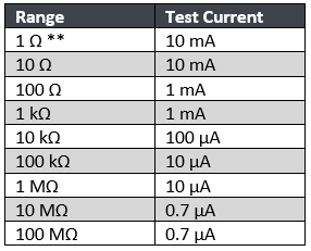
Q: There are footnotes above that state some lower resistance ranges are only applicable for the four-wire resistance function. Why is this? What are you trying to hide?
A: Nothing to hide, and glad you asked! Low-resistance measurements – those typically below 100Ω – are made using the four-wire method to eliminate the impact of any other resistive material in the target resistance path, and this is primarily test lead resistance.
The purpose of the DMM6500 (or any precision benchtop digital multimeter) is to provide you with the best measurements possible. We could enable the 1 Ω range in the two-wire measurement mode, but you won’t be able to evaluate the resistance value for what it truly is because the measurement will also be including the 10s to 100s (or more) of milliohms of (at least) test lead resistance.
We do allow you to apply the four-wire resistance measurement method on the 1 MΩ and higher ranges. However, on a 6 ½-digit instrument, you will not see 100s of milliohms in the readings because that is beyond the performance specifications of the instrument. Maybe we are just being accommodating and silly – hopefully a group of engineers is sitting around sharing a cup of coffee and a laugh about this sensitivity and resolution funny business.
Q: For those two lower ranges, is 10 mA adequate to drive such low-resistance values? I like to believe sourcing higher current for better stability is the way to go. Is there anything you can do to convince me otherwise?
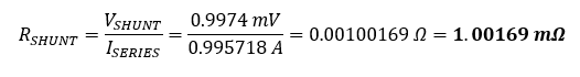
A: We can try…. Let’s measure the voltage and higher current (1 A) across a 1 mΩ precision shunt using the configuration below:
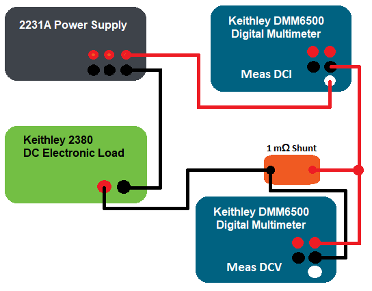
We set up one channel of a Keithley 2231A Power Supply so that it sources 5V with a current limit of 1.1A and the Keithley 2380 DC Electronic Load so that it sinks 1 A of constant current. We use one DMM6500 to measure current through the circuit and another to measure voltage across the 1 mΩ precision shunt, and witness the following on the front panels of the DMMs:
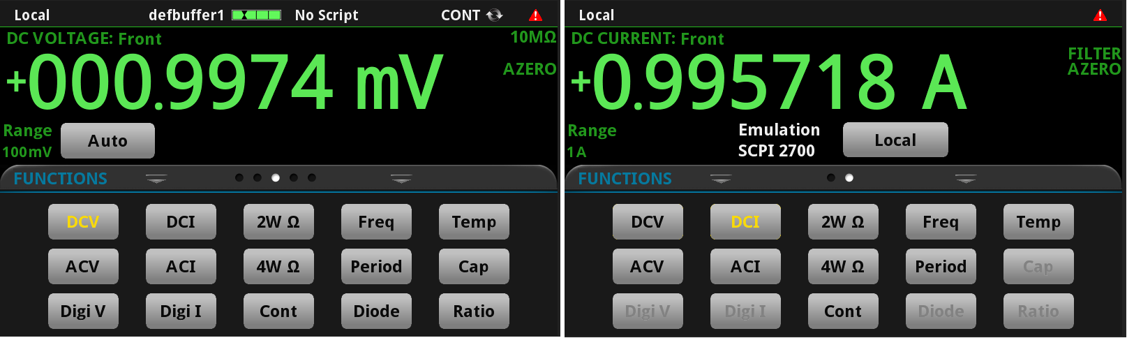
Both the current and voltage are very stable readings, and Ohm’s Law tells us that the resistance is:
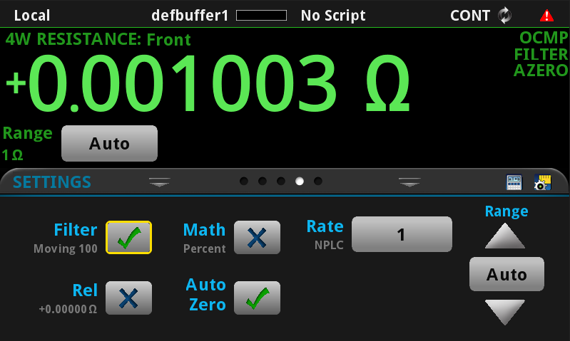
We then reconfigure and simplify the setup to measure with four-wire resistance as follows:
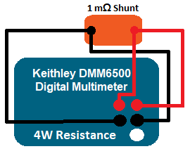
The reading on the display shows us the following:
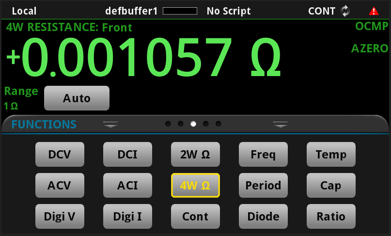
At first glance, this does not look as appealing as the calculated values obtained at higher current, appearing 5 percent off the previous setup. Does being off the ideal reading by this 5μΩ prevent you from reducing the instrument count? Maybe, maybe not.
If you were to watch the display, then you would witness what appears to be noisy or erratic readings that bounce around 1 mΩ. But, if you take the readings and average them, you will be able to better identify the mean as the final target value. This method works to our advantage.
We can stabilize this noisiness by applying a reading filter (we set for 100 samples using the “moving” option). Filtering collects the number of specified samples and provides the averaged value. When set to “moving,” the filter buffer moves old readings out, then in, one at a time, yielding a new averaged value with each new measurement. Working this way yields a much cleaner representation of the resistance. We could also choose the “repeating” filter option, which clears all the buffered readings and fully fills before providing the average and get the same performance. The updates are choppier and not as eye appealing, though.

We should also note that the Offset Compensation feature has been enabled to enhance the measurement.
Q: Where can I learn more about this “Offset Compensation” feature you mention?
A: This information can be found in the DMM6500 User Manual. Additionally, this and the four-wire resistance method are explained beautifully in Keithley’s Low Level Measurements Handbook available for download.
To learn more about best practices for making low-resistance measurements using a digital multimeter be sure to check out the video I mentioned earlier. More information is also available in the technical brief mentioned above and you can find complete information about the full range of Keithley products at https://www.tek.com/keithley.