By Chris Loberg
For the last few years, the PC industry seemingly went on hold while consumers went on a smart phone and tablet buying spree. Instead of peak performance, everyone wanted touch screens and longer battery life. But as the latest earnings report from Intel indicates, the PC is back. Turns out that if you want to do real work, there’s just no substitute for a speedy workstation, PC or laptop.
With renewed interest in PCs comes renewed interest in improving computing performance whether on desktops or in server rooms. One of the best ways to boost overall system performance is to incorporate faster memory, which bring us to the focus of this post: JEDEC’s DDR4.
Implemented in 2000 as a parallel architecture to read and write data onto dynamic RAM chips, DDR has evolved with increasing bandwidth requirements. The latest revision, DDR4, was announced by JEDEC in 2008 but has been slow to gain market traction due to the aforementioned shifts in end-customer interests.
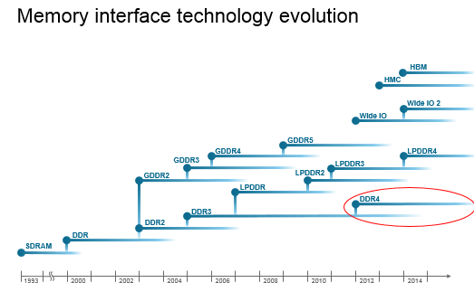
During the 2014 Intel Developer’s Forum in September, however, it became apparent that the market momentum for DDR4 is picking up. An increase in client PC sales and improving server markets are one indicator. Another is the adoption of DDR4 interfaces on Intel’s new Haswell platform in 2014. See the adoption curve below.

Now that DDR4 is moving into PC and server design projects, it’s valuable to consider some of the test challenges and how to prepare a lab for validation testing. The two key elements of this technology evolution from a test perspective are reduced operating voltage and higher read/write data rates. This means there’s little to no margin remaining. To prove the point, the chart below shows DDR4 going to 3,600 MHz, but now the plan is to top out at 3200 MHz. The concern in the JEDEC standards community is that there won’t be enough signal integrity margin to reliably deliver DDR4 applications beyond speeds of 3200 MHz.

This issue highlights the need to maintain good signal integrity when validating DDR4 electrical performance. Signal integrity begins with understanding the measurement tools you plan to use and the true performance margin you have available.
The fundamental electrical validation tool for all variations of DDR memory is an oscilloscope. Properly equipped oscilloscopes can trigger on reads or writes traveling on a memory bus and evaluate the critical timing parameters to ensure they’re in line with the JEDEC JESD79-4 spec for DDR4.
The table below shows the proper oscilloscope bandwidth needed for memory testing at the various speed grades of DDR. Given the higher data transfer rates of DDR4, it may be necessary to update oscilloscope models. Tektronix’ DPO/MSO70000 Series Oscilloscopes provide support for all bandwidth variations of DDR.

Another consideration when planning for DDR4 electrical validation testing is signal access and probing on the device under test. Accessing the memory bus at the point where it reaches the DRAM can be challenging with today’s dense packaging. Many packages have vias placed directly under other chips as in an embedded system. The development of signal interposers has helped greatly.
An interposer is a PCB which can be placed between the DRAM and memory bus processor and enables bus traffic to pass through while picking off signals for access from probes on the edge of the interposer’s PCB. See a video here that illustrates the operation and placement of an interposer on a package. There are interposers available for DDR4 which have been carefully designed not to disrupt the delicate signal integrity environment. In addition, it’s important to model the impedance and resistance impacts that the oscilloscope probe and interposers place on the actual signal. The oscilloscope then uses those models to de-embed these signal properties from the results. This keeps the measurement about the device, not the measurement system.
Once your measurement system is setup, it’s time to make measurements and perform analysis to ensure that the DDR4 memory bus is performing consistently with JEDEC specifications. Getting off to a good start begins with having an oscilloscope trigger intelligent enough to know what a READ or a WRITE burst looks like. An accurate evaluation of a DDR4 signal starts by capturing a burst. There are a couple of trigger types that can do this well.
The first is a WINDOW trigger as shown below. Window triggers look for a shift in positive or negative polarity in a signal’s voltage during the preamble just prior to a data burst. Once that is discovered, the trigger captures the data burst. From there, with the signal triggered, a visual view of the DDR4 “eye” becomes easy to validate or debug.

Another approach is to use a graphical trigger like a visual trigger shown below. Available on Tektronix oscilloscopes, visual triggers provide the oscilloscope user with a flexible set of graphical areas that can be placed on the scope’s graticule. Once created, these areas can trigger the scope when signals pass through them or around the area as the user desires.

The last step in electrical validation is performing analysis to the JESD79-4 standard. The Tektronix DDRA software package is an option on MSO/DPO70000 Series Oscilloscopes which provides all of the automated setup and test reporting you need to ensure smooth validation to the new JEDEC requirements. The package runs on the instrument and checks the memory bus for voltage and timing performance against reference levels directly out of the JEDEC spec. As seen below, the reporting tool provides pass/fail indications with links to the actual waveform location should failures occur and debug is needed.

A new addition for DDR4 are eye mask margin measurements on the data burst. This test requirement is included in the latest DDRA toolset as show in the screen capture below. The tool also provides precise voltage and time margin results from each corner of the JEDEC-specified eye mask.

As the DDR4 moves into 2014 and 2015 PC design efforts, it’s important to be ready in the lab with a comprehensive validation and debug solution. The increase in speed and decrease in operating voltage puts emphasis on good signal integrity to ensure that margin performance doesn’t constrain your validation efforts. For more information on DDR validation tools, visit www.tek.com/memory.