Introduction
Code Division Multiple Access technology emerged as an alternative to the GSM cellular architecture and has shared in the past decade’s explosive growth in the wireless market. CDMA,like GSM, has seen incremental improvements in capacity throughout this period. Now both types of networks are making a transition to third-generation (3G) systems around the globe, offering yet more capacity and data services.
This paper will briefly describe the origins of CDMA technology and the emergence of 3G implementations such as cdma2000 1X and cdma2000 1x EV-DO. An overview of network topology is included, with a detailed explanation of the role of each element and interface in the network and of protocol testing to address the changing requirements of the network. The paper concludes with a discussion of some of the technical problems that can occur in CDMA networks and some proposed solutions.
Digital Revolution and Evolution
When the mobile communications industry began its transition from first-generation analog technology to second-generation (2G) digital architecture, manufacturers and operators chose sides: in Europe, frequency-hopping GSM architecture became almost universal, while in the U.S., parts of Asia, and elsewhere, spread-spectrum CDMA technology took a large share of the market. Because spread spectrum uses wide band, noise-like signals, they are hard to detect. They are also difficult to intercept or demodulate. Further, spread spectrum signals are harder to jam (interfere with) than narrowband signals. These Low Probability of Intercept (LPI) and antijam (AJ) features are why the military has used spread spectrum for so many years. Both network implementations, GSM and CDMA, have advanced to keep pace with subscribers’ demands for more bandwidth, features and reliability at lower cost.
cdmaOne Helps 2G Mobile Communications Take Off
The Telecommunications Industry Association (TIA/EIA) IS-95 CDMA standard published in July 1993 established the ground rules for a complete end-to-end digital wireless communications system. The commercial network system architecture based on this standard is known as cdmaOne. TIA/EIA IS-95 and the subsequent IS-95A revision (published in May 1995) form the basis for most of the commercial 2G CDMA-based networks deployed around the world.
From the standpoint of voice services, cdmaOne technology offers important features for mobile network operators:
- An 8X to 10X increase in voice capacity increase compared to analog AMPS systems
- Simplified network planning, with the same frequency used in every sector of every cell
The early 2G CDMA infrastructure proved its effectiveness in delivering high-quality, low-loss voice traffic to subscribers. But it didn’t take long for mobile users to begin asking for basic data services, such as Internet and Intranet services, multimedia applications or high-speed business transactions, to supplement the voice services on their handsets. The TIA/EIA IS-95A standard answered this demand with its definition of the wideband 1.25 MHz CDMA channels, power control, call processing, hand-offs and registration techniques for system operation. TIA/EIA IS95A brought true circuit-switched data services to CDMA subscribers; however, these were limited to a maximum speed of 14.4 Kbps per user.
A second round of revisions to the original specification produced the TIA/EIA IS-95B standard. This new development gave subscribers packet-switched data services at speeds up to 64 Kbps per subscriber in addition to the existing voice services. With this increased data rate, TIA/EIA IS95B-compliant networks qualify as 2.5G CDMA technology.
cdma2000 Takes the Next Step
The transition to 3G networks, still underway, began with a profusion of newly proposed standards. Some were designed to build on GSM infrastructures and others emerged directly from CDMA technology. Ultimately the ITU took a position on the matter, defining an IMT-2000 standard that encompassed five different radio interfaces including cdma2000. Note that all of the IMT-2000 protocols use spread-spectrum techniques, which has implications about network installation, operation and maintenance.
The ITU defines a 3G network as one that delivers, among other capabilities, improved system capacity and spectrum efficiency versus 2G systems. It supports data services at transmission rates of at least 144 Kbps in mobile (moving) environments and at least 2 Mbps in fixed (indoor) environments. The cdma2000 architecture meets these objectives and includes several implementations that an operator can select to best serve a transition strategy based on competitive concerns, existing infrastructures, cost, and other variables.
Among these implementations are cdma2000 1X and cdma2000 1xEV:
- cdma2000 1X doubles the voice capacity of cdmaOne networks, delivering peak data rates of 307 Kbps per subscriber in a mobile environment.
- cdma2000 1xEV includes two variants, both backward compatible with cdma2000 1X and cdmaOne technologies.
- cdma2000 1xEV-DO (Data Only), capable of delivering data multimedia services such as MP3 transfers and video-conferencing at peak data rates of 2.4 Mbps per subscriber in a mobile environment;
- cdma2000 1xEV-DV (Data Voice), capable of delivering integrated voice and simultaneous data multimedia services at peak data rates of 3.09 Mbps per subscriber.
A Network Structure Designed for Packetized Communication
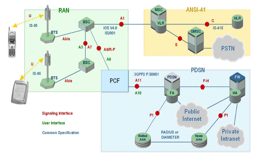
Figure 1 illustrates a simplified cdma2000 1X network, showing both the telephony (ANSI-41) and data structures. Refer to Figure 1 for the following discussion.
The Mobile Station (MS)
In a cdma2000 1X network, the mobile station—the subscriber’s handset—functions as a mobile IP client.
The mobile station interacts with the Access Network to obtain appropriate radio resources for the exchange of packets, and it keeps track of the status of radio resources (e.g. active, stand-by,dormant). It accepts buffer packets from the mobile host when radio resources are not in place or are insufficient to support the flow to the network.
Upon power-up, the mobile station automatically registers with the Home Location Register (HLR) in order to:
- Authenticate the mobile for the environment of the accessed network
- Provide the HLR with the mobile’s current location
- Provide the Serving Mobile Switching Centre (MSC-S) with the mobile’s permitted feature set
After successfully registering with the HLR, the mobile is ready to place voice and data calls. These may take either of two forms, circuit-switched data (CSD) or packet-switched data (PSD), depending on the mobile’s own compliance (or lack thereof) with the IS-2000 standard. This document defines protocols for several critical CDMA interfaces pertaining to packet transmission, namely A1, A7, A9, and A11.
Mobile Stations must comply with IS-2000 standards to initiate a packet data session using the 1xRTT1 network. Mobile stations having only IS-95 capabilities are limited to CSD, while IS-2000 terminals can select either the PSD or CSD. Parameters forwarded by the terminal over the air link (AL) to the network will determine the type of service requested.
Circuit-switched data has a maximum rate of 19.2 Kbps and is delivered over traditional TDM circuits. This service allows users to select the point of attachment into a data network using ordinary dialled digits.
Packet-switched data service has a maximum data rate of 144 Kbps. For each data session a Point-to-Point Protocol (PPP) session is created between the mobile station and the Packet Data Serving Node (PDSN). IP address assignment for each mobile can be provided by either the PDSN or a Dynamic Host Configuration Protocol (DHCP) server via a Home Agent (HA).
The Radio Access Network (RAN)
The Radio Access Network is the mobile subscriber’s entry point for communicating either data or voice content. It consists of:
- The air link
- The cell site tower/antenna and the cable connection to the Base Station Transceiver Subsystem (Um)
- The Base Station Transceiver Subsystem (BTS)
- The communications path from the Base Station Transceiver Subsystem to the base station controller (Abis)
- The Base Station Controller (BSC)
- The Packet Control Function (PCF)
The RAN has a number of responsibilities that impact the network’s delivery of packet services in particular. The RAN must map the mobile client identifier reference to a unique link layer identifier used to communicate with the PDSN, validate the mobile station for access service, and maintain the established transmission links.
The Base Station Transceiver Subsystem (BTS) controls the activities of the air link and acts as the interface between the network and the mobile. RF resources such as frequency assignments, sector separation and transmit power control are managed at the BTS. In addition, the BTS manages the back-haul from the cell site to the Base Station Controller (BSC) to minimize any delays between these two elements. Normally a BTS connects to the BSC through un-channelized T1 facilities or direct cables in co-located equipment. The protocols used within this facility are proprietary and are based on High-level Data Link Control (HDLC).
The Base Station Controller (BSC) routes voice- and circuit-switched data messages between the cell sites and the MSC. It also bears responsibility for mobility management: it controls and directs handoffs from one cell site to another as needed. It connects to each MTX using channelized T1 lines for voice and circuit switched data; and to un-channelized T1 lines for signalling and control messages to the PDSN using the 10BaseT Ethernet protocol.
The Packet Control Function (PCF) routes IP packet data between the mobile station within the cell sites and the Packet Data Serving Node (PDSN). During packet data sessions, it will assign available supplemental channels as needed to comply with the services requested by the mobile and paid for by the subscribers.
1 A network that provides a “1x chip rate of 1.2288 Mcps for Radio Transmission Technology.”
The PCF maintains a “reachable” state for between the RN and the mobile station, ensuring a consistent link for packets; buffers packets arriving from the PDSN when radio resources are not in place or insufficient to support the flow from the PDSN; and relays packets between the MS and the PDSN.
The Core Network’s Role in the CDMA Infrastructure
The Packet Data Serving Node / Foreign Agent (PDSN/FA)
The PDSN/FA is the gateway from the RAN into the public and/or private packet networks. In a simple IP network, the PDSN acts as a standalone Network Access Server (NAS), while in a mobile IP network it can be configured as a Home Agent (HA) or a Foreign Agent (FA).
The PDSN does the following activities:
- Manage the radio-packet interface between the BSS (Base Station Subsystem = BTS + BSC) and the IP network by establishing, maintaining and terminating link layer to the mobile client
- Terminate the PPP session initiated by the subscriber
- Provide an IP address for the subscriber (either from an internal pool or through a DHCP server or through an AAA server; see below)
- Perform packet routing to external packet data networks or packet routing to the HA which optionally can be via secure tunnels
- Collect and forward packet billing data
- Actively manage subscriber services based on the profile information received from the SCS server of the AAA server
- Authenticate users locally, or forward authentication requests to the AAA server
The AAA Server
The AAA (Authentication, Authorization, and Accounting) server is used to authenticate and authorize users for network access and to store subscriber usage statistics for billing and invoicing.
The Home Agent
The Home Agent (HA) supports seamless data roaming into other networks that support 1xRTT. The HA provides an anchor IP address for the mobile and forwards any mobile-bound traffic to the appropriate network for delivery to the handset. It also maintains user registration, redirects packets to the PDSN and (optionally) tunnels securely to the PDSN. Lastly, the HA supports dynamic assignment of users from the AAA and (again optionally) assigns dynamic home addresses.
Detecting and Solving Some Common Problems in cdma2000 1X Networks
All of the features and capacities embodied in the modern 3G mobile network make for a complex system with many modes, nodes, elements, interfaces, and protocols. Problems, when they arise, may have their origins in either hardware or software. As mobile Internet connectivity becomes common, the challenge of maintaining uninterrupted data transactions will require new, more powerful monitoring solutions and procedures, among other things. In this section, we will examine some common problems that can occur in cdma2000 1X networks.
Failure in Mobile Initiated Packet Data Call Set-up and Mobile IP Registration
In order to obtain packet data services, the mobile performs registration with the serving wireless network on the A1 interface and then with the packet network on the A10/A11 interface. The mobile sends an Origination Message to the BS that includes the packet data service option. This results in assignment of the traffic channel, establishment of the A10 connection, establishment of the link layer (PPP) and for the case where Mobile IP is used by the terminal, Mobile IP registration with the serving packet network.
User data traffic can now be passed over the A10 connection encapsulated within GRE frames.The PCF periodically re-registers with the selected PDSN by sending the A11-Registration Request message before the A10 connection Lifetime expires.
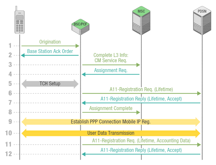
A successful call set-up scenario is illustrated in Figure 2. This standard message sequence chart outlines a series of steps, summarized in items 1-12 to follow. Note that this explanation bypasses the radio reception/transmission activities of the BTS, concentrating instead on the protocol functions that begin with the Origination dialogue between the mobile and the BSC.
- To register for packet data services, the mobile sends an Origination Message over the Access Channel to the BSS
- The BS acknowledges the receipt of the Origination Message, returning a Base Station Ack Order to the mobile
- The BS constructs a CM Service Request message and sends the message to the MSC.
- The MSC sends an Assignment Request message to the BSS requesting assignment of radio resources. No terrestrial circuit between the MSC and the BS is assigned to the packet data call.
- The BS and the mobile perform radio resource set-up procedures.
The PCF recognizes that no A10 connection associated with this mobile is available and selects a PDSN for this data call. - The PCF sends an A11-Registration Request message to the selected PDSN.
- The A11-Registration Request is validated and the PDSN accepts the connection by returning an A11-Registration Reply message.
Both the PDSN and the PCF create a binding record for the A10 connection. - After the radio link and A10 connection are set-up, the BS sends an Assignment Complete message to the MSC
- The mobile and the PDSN establish the link layer (PPP) connection and then perform the MIP registration procedures over the link layer (PPP) connection.
- After completion of MIP registration, the mobile can send/receive data via GRE framing over the A10 connection.
- The PCF periodically sends an A11-Registration Request message for refreshing registration for the A10 connection.
- For a validated A11-Registration Request, the PDSN returns an A11-Registration Reply message.
Both the PDSN and the PCF update the A10 connection binding record.
This necessarily complex process can be the source of some problems that affect service and quality. A rigorous monitoring scheme involving simultaneous observation of the A1 interface and the A10/A11 interface is the best way to detect and correct errors early. Here, a multi-interface call-trace application is especially productive, since it can trace and group all of the procedures related to the activity of each single subscriber in a CDMA network, even as the procedures evolve over multiple interfaces
Within the call set-up process, an error in any element or procedural step can inhibit the remaining steps. For example, suppose that the MSC does not respond to the CM Service Request message (Step 3 in Figure 2) sent by the BSC/PCF over the A1 interface. This is sometimes caused by internal MSC problems. If this prevents the CM Service Request from reaching completion, the BSC/PCF cannot assign radio resources to the mobile station, in turn preventing establishment of the connection. The user finds it impossible to make a data call—a service for which he or she has paid a premium.
Before a specific timer expires, the PCF sends periodically A11-Registration Request message (Step 11) to refresh the registration for the A10 connection. For a validated A11-Registration Request, the PDSN returns an A11-Registration Reply message (Step 12). Here again, internal problems in the PDSN can cause it to respond late or not at all. As a result the process of establishing or maintaining the connection cannot continue. The user is once again unable to make a data call.
In both cases, a protocol analyzer connected to the A1 and A10/A11 interfaces can help track down the problem. The call trace application can distinguish the origin of messages and detect any failure to respond. This makes it easy to pinpoint the MSC and the PDSN, respectively in these examples.
Inefficiency in User Data Packet Transmission
Frequently in a cdma2000 network the TCP user-plane packets have a small Window Size. This implies that end-to-end TCP connections are not stable. The more TCP packets lost in the network and not acknowledged, the smaller the Window Size, with the result that more TCP connections are dropped and re-established. The small TCP Window Size is a by-product of the soft-start mechanism built into the TCP protocol.
To characterize this problem, it is necessary to capture the TCP/IP user plane packets flowing on the GRE tunnels on the A10 interface. Protocol filtering allows the tool to home in on just the data or interest. By applying different types of filtering with increasing level of details, it is possible to “drill down” and isolate the root cause of the shrinking TCP packet Window Size.
Routing Loops of User Data Packets in the Core Network
“Tunnel router loops” are another class of cdma2000 network problems that can degrade the quality of service for subscribers. The problem is caused by misconfiguration in the PDSN routers. It can be detected by acquiring and analyzing IP traffic on the P-H interface (see Figure 1).
To understand tunnel router loops, imagine a subscriber surfing the Web (WWW) with a laptop connected to a cdma2000 handset. Packets addressed to go to a specific HTTP proxy are routed (after passing through the PCF) from the PDSN/FA (Foreign Agent) to the Home Agent (HA) for de-tunneling.
With certain incorrect internal routing configurations, packets destined for Port 80 WWW are not de-tunnelled by the HA. Instead, they are sent back downstream toward the PDSN/FA. As a result, multiple packets travel on the same network segment with the same packet ID, wasting precious bandwidth—and not reaching the intended destination. In addition, for each repetitive hop a packet takes between the PDSN/FA and HA nodes, the IP Time To Live (TTL) field is decremented. If the packet is stuck in a router loop, the TTL eventually decrements all the way to zero and the packet is discarded by the network nodes. “Lost” packets must be retransmitted, leading to excessive packet retransmission overhead and reduced throughput.
As in the earlier examples, the solution is to use protocol filtering to capture IP packets on the PH interface. Browsing through the captured data by applying increasingly fine levels of filtering, it is possible to see the repeating packets and resolve the problem.
Duplication of IP traffic
PDSN configuration problems can give rise to other types of problems in addition to tunnel loops. One common issue is associating the PDSN´s logical IP addresses with more than one physical MAC address. When this occurs, more than one hardware card has the same IP address. All traffic sent to that IP address goes to two different hardware entities and receives responses from both. This effectively doubles the amount of IP traffic associated with that single IP address on that segment. Once again, protocol filtering capabilities are required for effective troubleshooting. A protocol analyzer should capture IP packets travelling to a specific IP destination address via the P-H interface. Browsing through the data and using filtering to successively narrow down the inquiry, the nature of the problem (the duplicated address) soon becomes apparent.
Routing problems in the Core Network
Sometimes internal problems can cause PDSN routers to go offline and come back online after a period of time. This can happen frequently and continuously in a cdma2000 core data network. When a router first comes online its routing table are not optimized. It takes time for the built-in OSPF (Open Shortest Path First) routing algorithm to learn the best way to route packets depending on adjacent available routers. Until the routing tables are optimized, there will be degradation in quality of service.
By capturing IP packets on the P-H interface with a protocol analyzer and applying filters on the OSPF routing messages, changes in designated router and changes in neighbours of a router can be easily identified. Using intelligent and detailed filtering capability on OSPF messages and information elements within these messages identifying routing problems on an IP network becomes an easy task.
Conclusion
CDMA infrastructure is widespread and sure to form the basis for broad penetration of CDMA networks. cdma2000 and other 3G technologies bring telecommunications into the packetswitched domain, adding a host of new services and network complexities in the process.
Troubleshooting activities now require an understanding of both traditional “telecom” concepts related to the circuit-switched domain and new “datacom” concepts related to the packet switched-domain. Network operation and maintenance personnel must refine their processes to meet complex new troubleshooting challenges. These range from misconfiguration problems to duplicated IP addresses and more. Protocol analysis tools can play a bigger role than ever in keeping a network running efficiently. Features such as multi-interface call tracing and protocol filtering will become critical to the job of maintenance.