Technical Brief
Introduction
The PCI Express (PCIe) CEM Specification requires testing both transmitters and receivers to ensure that devices comply with the specification. Tektronix provides automated BERT receiver (RX) stress calibration and receiver test software for PCIe 6.0 CEM testing.This software automates the calibration process for a system composed of a Tektronix DPO70000SX real time oscilloscope and Anritsu MP1900A Bit Error Rate Tester (BERT). Features are implemented in TekRXTest Software publicly available today supporting RX characterization, debug, pre-compliance and compliance testing per the 6.0 CEM specification.
TekRxTest software offers a wizard-based approach to intuitively guide users through the complex receiver calibration process. The process, when done manually, can easily take two to three days, while with this new solution calibration can typically be completed in hours.
TekRxTest implemented the following unique approaches to make it more efficient than other available techniques:
- Patented Tx EQ calibration shortens the process from several hours on comparable systems to ~30 mins, without compromising accuracy required by the specifications.
- Hardware accelerated FastFrame™ approach shortens the waveform averaging process required in the TP2 calibration process by hours.
In addition, TekRxTest integrated receiver calibration and testing supports testing for all generations of the PCI Express standard.
Background
PCIe receiver testing specifies the calibration of test signals. During actual operation of a high speed serial link, numerous impairments will close an eye. PCIe standards offer a well-defined CEM Test Spec that specifies combinations of impairments to use for testing. Stressed eye targets are defined with the full pad-to-pad channel, with Compliance Base Board (CBB) and Compliance Load Board (CLB) in the path through the CEM connector. The BERT PPG acts as a surrogate PCIE transmitter in the scenario of receiver testing. Once the recipe for the stressed eye target is determined, one removes the fixturing that isn’t used in testing — CLB for Add-In-Card testing, or CBB for System testing. This effectively refunds the loss budget permitted for the device-under-test (DUT).
Users must perform BERT stress calibration before RX tests are conducted on a DUT. This BERT calibration ensures the magnitude of stresses applied to the DUT RX are in accordance with PCIe 6.0 spec limits. This RX testing determines RX pass/fail and margin performance. During BERT stress calibration, the user controls multiple parameters during the calibration run. Receiver stressed eye calibration is a complex, iterative process and human error is a significant risk. As such, manual calibration is unsustainable for routine testing. This technical brief discusses those controls and provides recommendations to maximize the probability of successful calibration after all steps are complete. Guidance is given on when different modes should be used, and troubleshooting tips are provided.
TekRXTest RX Software
TekRXTest is a software framework that supports automated BERT stress calibration for multiple technologies including PCIe 6.0 CEM. Figure 1 shows the start screen for TekRXTest, and the RX personalities supported as of May 2025.
More info on TekRXTest is available here.
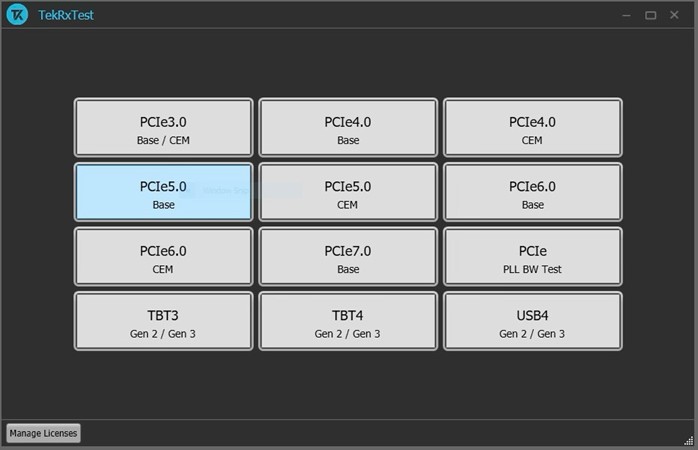
Figure 1. Start screen for TekRXTest and RX personalities.
BERT Stresses For PCI Express 6.0 CEM
BERT stress calibration for PCIe 6.0 RX testing is broken into two parts: short channel (TP3, Figure 3) and long channel (TP2, Figure 2). TP3 signal validation is performed first with BERT output signals connected directly through RF coaxial cables to scope inputs. BERT tests using TP3 connections are pulse width jitter, differential amplitude, AC-DC balance, preset, random jitter (RJ) and sinusoidal jitter (SJ). 6dB external attenuators should be installed on the front of each oscilloscope ATI channel to ensure the best combination of voltage range and noise performance. These attenuators are available as part of the DPO7RFKx connector kits from Tektronix.
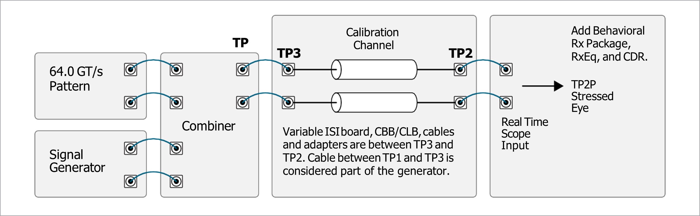
Figure 2. Long channel BERT stress calibration for PCIe 6.0 RX testing.
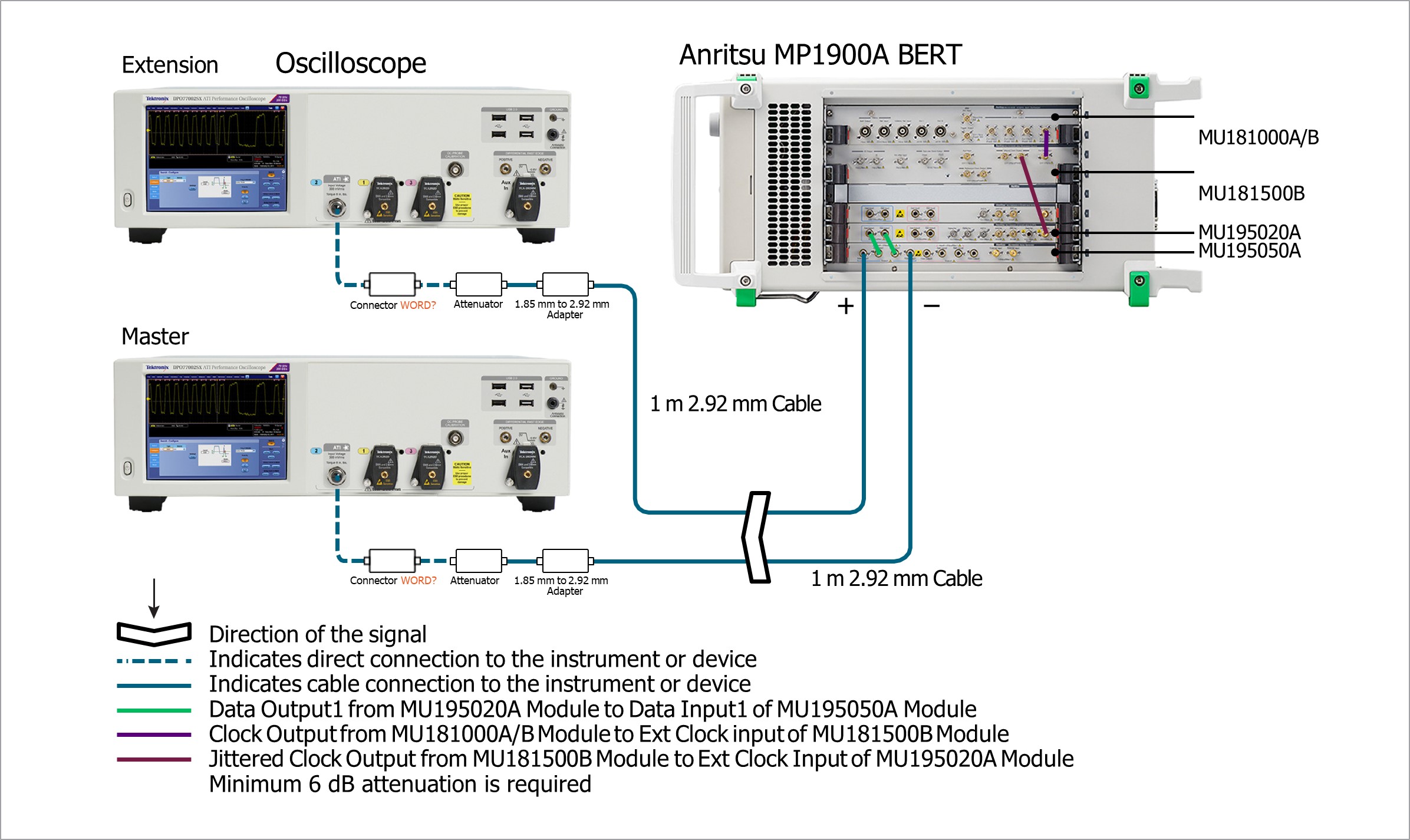
Figure 3. Short channel BERT stress calibration for PCIe 6.0 RX testing.
Once TP3 calibrations are complete, a differential loss ISI channel is added between the BERT PPG and scope inputs. An example connection diagram is shown in Figure 4. TP2 calibrations are performed including insertion loss (IL) verification, common-mode interference (CMI) and differential mode interference (DMI), optimal preset and CTLE selection and stressed eye. Final stressed eye parameters are compared to spec limits to determine successful completion of the BERT calibration.
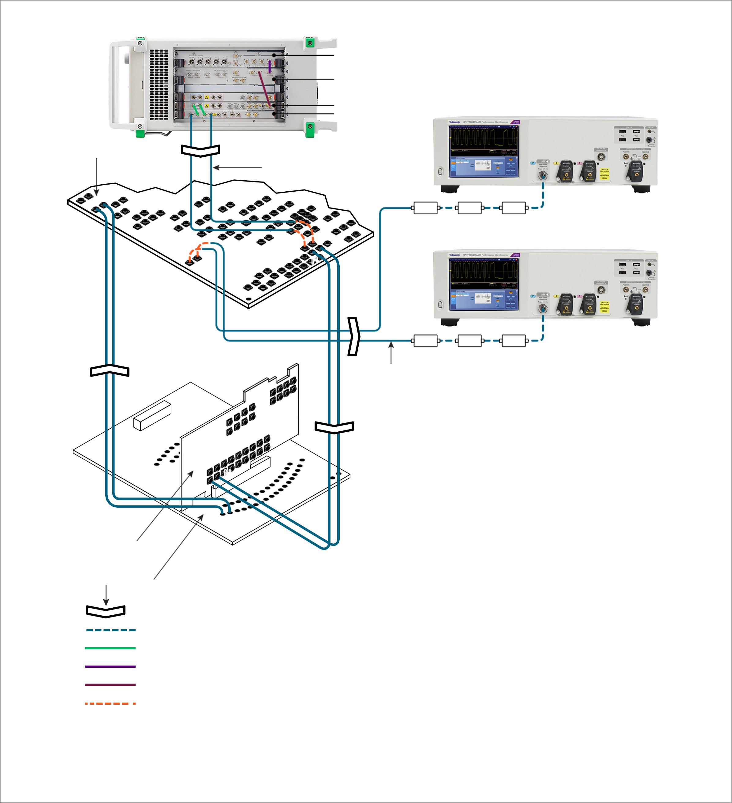
Figure 4. Example connection diagram showing a differential loss ISI channel added between the BERT PPG and oscilloscope inputs.
User Controls During BERT Calibration
TekRXTest Software prompts the user to specify some settings prior to performing TP3 and TP2 BERT stress calibration.
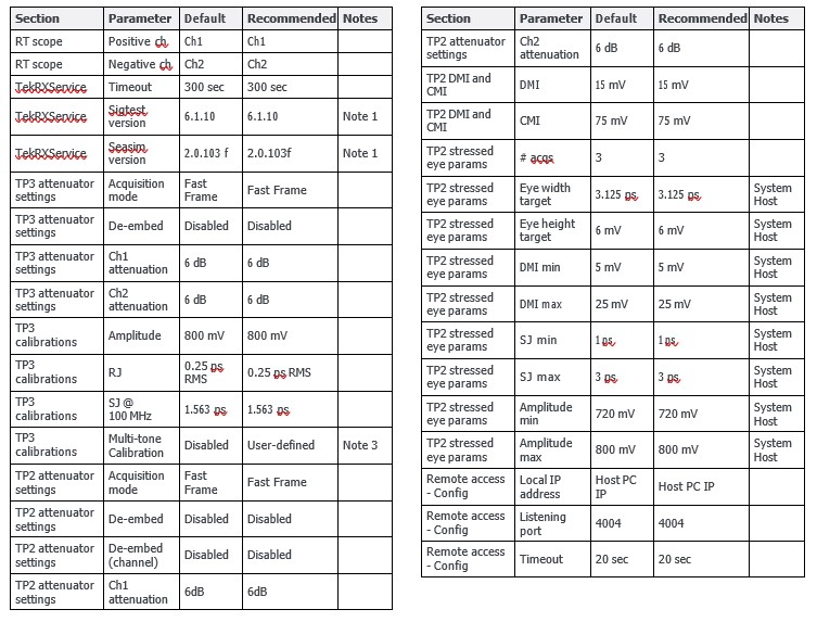
Table 1 lists these controls, their description, and how to set these values to complete a successful calibration.
Table 1. List of parameters set during calibration.
Note 1: Versions of Sigtest & SEASIM will be updated when fully tested and recommended by PCI-SIG.
Note 2: Although not required for PCIe 6.0 CEM-RX pass/fail testing, the user may enable JTOL testing with up to 14 SJ separate frequency tones to perform RX margin testing. These SJ tones must be calibrated during TP3.
User settings:
Launch & Run TP3 Calibration
When a user starts a short channel calibration, the RX software provides a connection diagram to ensure signals are connected properly from the BERT PPG to the scope inputs. Proper care should be used in making RF connections between cables and components. (Details are not covered in this technical brief). Refer to the High Performance Oscilloscopes Best Practices Manual and DPO70000SX Quick Start User Manual, and use good lab practices. For assistance making proper connections, please contact your local Tektronix field application engineer.
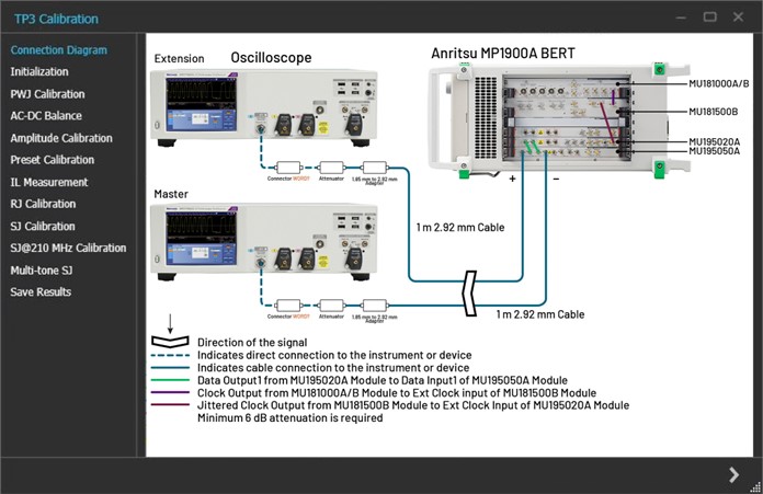
Figure 5. TP3 calibration connection diagram.
With RX software launched and “connected” via IP address to scope and BERT, the user may INITIALIZE equipment for TP3 calibration. The RX software will automatically initialize instruments when the user clicks the INITIALIZE EQUIPMENT button within TP3 calibration test flow. Initialization of the scope and BERT takes less than five minutes. By default, the scope will perform signal validation during the initialization process. To speed up initialization, the user may select the check-box to SKIP SIGNAL VALIDATION DURING INITIALIZATION. These controls are shown in Figure 6 below.
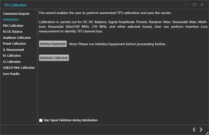
Figure 6. TP3 calibration connection wizard showing the Initialization steps.
The user may run all TP3 calibrations automatically, or one at a time. It is recommended that new users manually perform and observe results for each calibration step. Manual mode is also recommended if hardware setup is new to ensure each TP3 calibration test completes correctly. For subsequent stress calibration runs, auto mode may be considered.
Baseline pulse width jitter (PWJ) is needed during TP3 to provide a reference for Seasim. During the PWJ Calibration step, the user may opt for the scope to measure PWJ (default), or enter known values for PWJ RJ and PWJ DJ for their specific setup.
When PWJ Calibration is complete, the next three calibration steps will proceed without user input (AC-DC balance, Amplitude, Preset). During the Preset calibration step, all presets (Q0 to Q9) are calibrated. An IL measurement is performed after Preset and is required only if the user plans to perform IL verification step during TP2. If the user will use VNA loss measurements to establish and adjust ISI channel losses during TP2 calibration, TP3 IL measurement step can be skipped to save time. If the IL measurement step is performed, the scope will measure short-channel loss (specify # scope acquisitions and # averages) using step response from BERT and analysis via Seasim. The user may alternatively manually enter in the short-channel loss (dB at 16 GHz) if known.
The next three calibration steps will proceed without user input (RJ, SJ, SJ@210MHz). After the last TP3 calibration step is complete, the user may provide information to identify the calibration: Unique ID, Generated by, and comments field. Click the SAVE button to save this TP3 calibration in the RX software for future use.
Multi-tone SJ Calibration
The user may enable multi-tone SJ calibration during TP3 to perform JTOL margin testing. The multi-tone SJ feature is disabled by default but may be enabled in SETTINGS ➞ TP3 Calibrations via checkbox. Longer calibration times will be incurred the more SJ frequencies that are specified (about five to seven minutes per SJ tone), and the higher number calibration points tested between Min and Max SJ values. Even after passing compliance testing, it may be desirable to test design margins. TekRXTest software makes it straightforward to retroactively add multi-tone SJ calibration to an existing TP3 calibration.
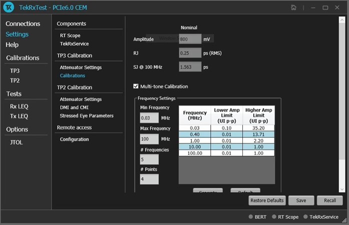
Figure 7. Configuring multi-tone SJ frequency and amplitude.
The multi-tone SJ feature supports:
- SJ sweep across frequencies from 30 kHz up to 100 MHz.
- ≤14 SJ frequencies.
- Two to eight calibration points per SJ frequency.
- Min SJ value determined by BERT hardware intrinsic jitter.
- Max SJ value determined by BERT hardware SJ limits.
TP3 Calibration Time
TP3 calibration takes about 45 minutes using default software settings. This run-time assumes hardware and software prerequisites are met, proper communication exists between the host PC running TekRXTest and the test instruments, correct connections are made per connection diagrams and instruments are in good working order.
Several factors allow TP3 calibrations to run faster:
- Skip signal validation during initialization.
- Manually enter BERT PWJ values.
- Skip IL measurement if using VNA to measure ISI channel loss in TP2.
- Use auto-calibration mode.
Several factors will cause longer TP3 run-time including:
- Signal validation during initialization.
- Performing BERT PWJ measurement.
- Performing short-channel IL measurement.
- Using manual run mode, and pausing between calibration steps.
Launch & Run TP2 Calibration
The same RF cables used to connect the BERT PPG to the scope inputs during TP3 calibration should remain in place when performing TP2 calibration. In the shift from TP3 to TP2 setup, these RF cables are disconnected from scope inputs and connected to PCI-SIG 6.0 CEM test fixtures. These connections are shown in Figure 8 below.
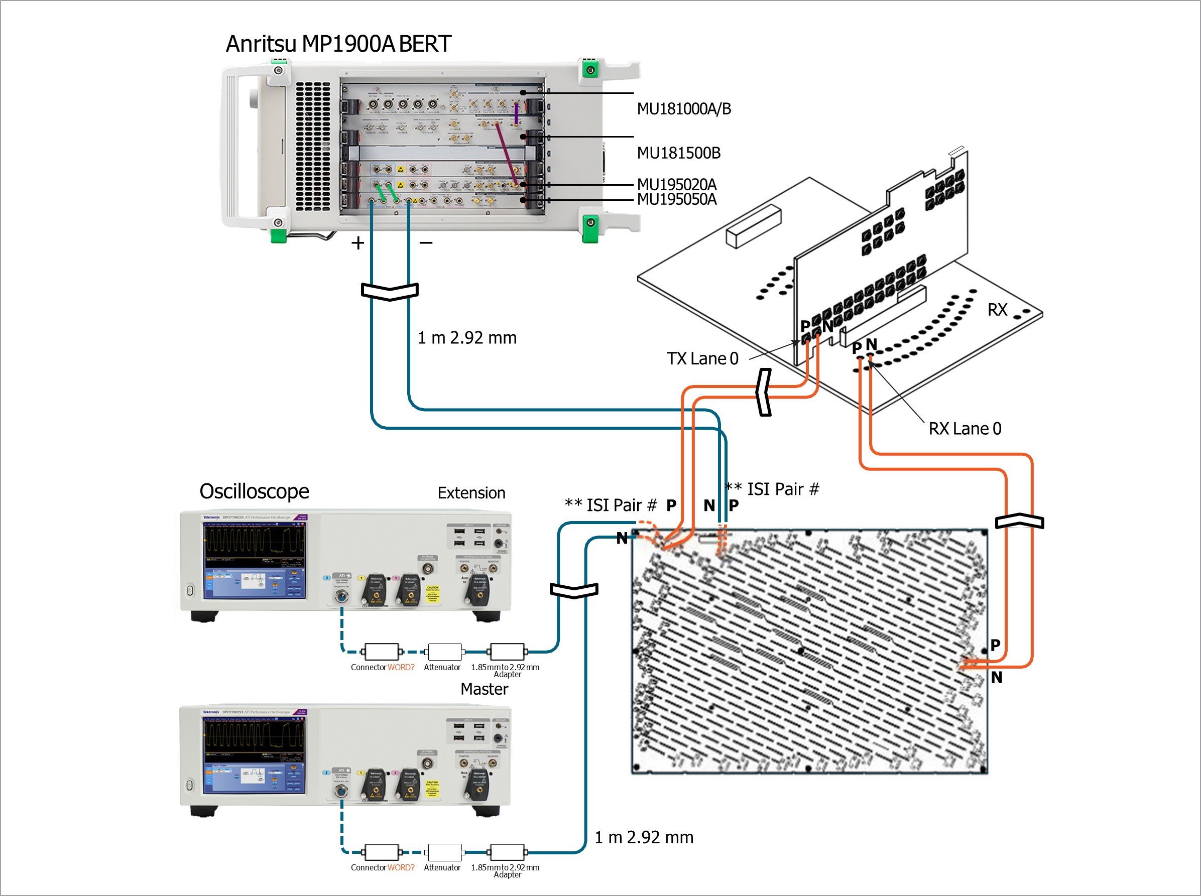
Figure 8. TP3 and TP2 RF cable connection.
The user must perform and save a TP3 short channel calibration prior to running a long channel calibration. TP2 stress calibration will prompt the user for DUT type (System Host or Add-in Card) and the TP3 calibration to use for TP2 calibration. Similar to TP3:
- TekRXTest software provides a connection diagram to ensure signals are connected properly from BERT PPG to the scope inputs. See Figure 8.
- The user will initialize instruments using INITIALIZE EQUIPMENT button before performing TP2 calibration steps.
- TP2 calibration settings are provided in the SETTINGS menu. These user settings are shown in Table 1.
- TekRXTest software provides BERT calibration steps that may be run manually (one at a time) or in auto mode.
- TP2 test report with plots and BERT calibrated values are available upon completion.
ISI Channel Loss
The user should acquire approved PCIe 6.0 fixtures including ISI board and cables from PCI- SIG to enable signal path connections shown in Figure 8. VNA insertion loss measurements are recommended on ISI channel fixtures and associated cables to ensure the prescribed amount of loss is in place during TP2 calibration.
Target ISI channel loss depends on whether a System Host or Add-in Card is being tested. For System Host, the total ISI channel loss target is 24 dB @ 16 GHz (Add-in Card is 28 dB @ 16 GHz). These targets are shown in the RX software at the IL for DMI/CMI calibration step shown in Figure 9 below
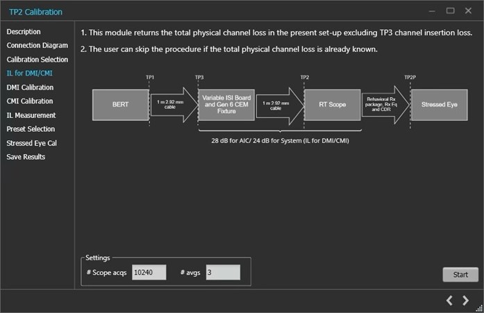
Figure 9. TP2 calibration targets.
PCIe 6.0 ISI channel loss boards provide traces with about 0.5 dB loss increments to allow for adjustment. The user will vary channel loss together with other BERT stress parameters to meet stress calibration closure requirements. Because each ISI board will vary in its loss profile, it is recommended the user measure ISI channel loss on the fixture to be used prior to TP2 calibration. The goal is to identify a cable + ISI channel pair that exhibit the target channel loss (24 dB @ 16 GHz for System Host, 28 dB @ 16 GHz for add-in card). It is Tektronix’ experience that lanes meeting ISI channel requirements do vary. Actual convergence during the March 2025 pre-FYI plugfest was obtained using ISI pair 2 and 14 for System Host, ISI pair 23 and 0 for Add-in Card. This lane variation is dependent on RF cable, connector and fixture loss differences.
TekRXTest software will embed the appropriate package loss onto the scope’s acquired waveform during TP2 calibration so that the step waveforms passed to Seasim represent the entire 30-33 dB ISI channel loss required for CEM compliance testing. This total loss is shown in the IL Measurement in Figure 10.
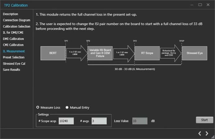
Figure 10. Total package loss.
Once an ISI channel is chosen, TP2 stress calibration can begin. The recommendation from PCI- SIG is to begin with max ISI channel loss for initial TP2 calibration run. The user may perform the IL measurement for DMI/CMI step, but this step is optional and may be skipped if VNA measured data was used to verify target channel loss. DMI and CMI calibrations will run without any user input. At the IL Measurement step, the user may select MANUAL ENTRY and enter in the total ISI channel loss (i.e. VNA measured loss + embedded package loss). For System Host this target is 30-33 dB
Optimal preset calibration is performed next shown by Figure 11. The user may use the CONFIGURATION button to determine what presets are considered during this step (Q0 to Q9). As shown in Figure 11, presets Q5, Q6, Q8, Q9 were selected based on recommendation from PCIe 6.0 PHY Test spec working group. In Tektronix’ experience, successful calibrations have been achieved using Q5, Q7 and Q8. The user may control the number of acquisitions for optimal preset step. The default number of acquisitions is three, but this value may be increased to ≥5, resulting in more waveform averages used to for preset eye area calculation.
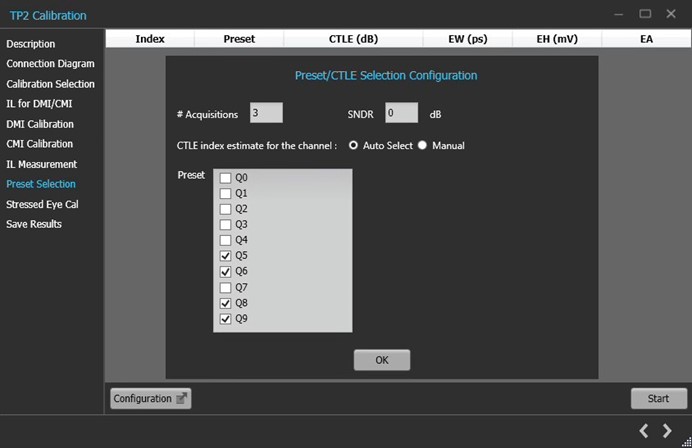
Figure 11. Optimal preset calibration.
TekRXTest software will choose the preset resulting in the largest average eye area. In the example shown in Figure 12, preset Q5 was found to yield the highest eye area of 5.274. In this example, the RX software will use Q5 in the final Stressed Eye Cal step.
In some cases, more than one preset may result in a large eye area. To choose the best preset, the ratio of eye width / eye height should be evaluated. With these ratios computed, the preset resulting in the ratio being closest to 50% is recommended. An example is provided below:
Converged eye #1:
Preset = Q5
Eye width (EW) = 1.484
Eye height (EH) = 3.554
Ratio = EW / EH = 0.42
Converged eye #2:
Preset = Q7
Eye width (EW) = 1.645
Eye height (EH) = 3.487
Ratio = EW / EH = 0.47
Choose this setting
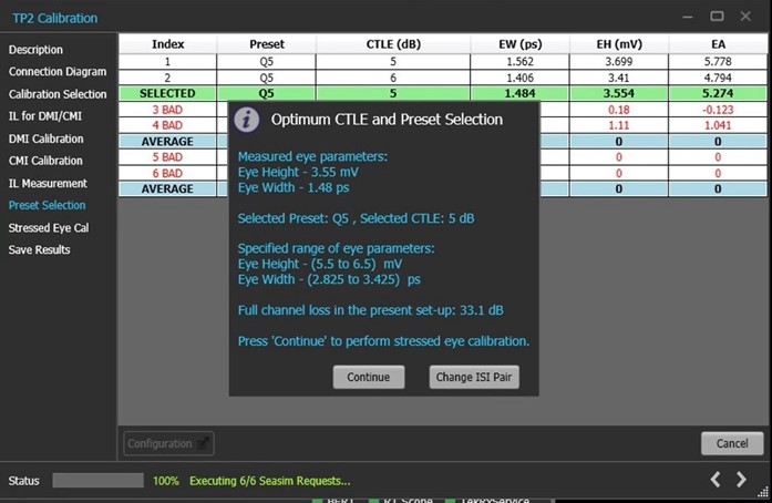
Figure 12. TP2 calibration optimum CTLE and preset selection example. Note that the “Bad” results for Q8, Q9 presets are normal in this case, when searching for the optimum CTLE.
Final calibration step is Stressed Eye Cal. This step uses the preset determined in the previous step yielding the largest eye area. With this preset configured in the BERT, a step waveform is captured and averaged then sent to Seasim for analysis. Tektronix has implemented HW- assisted 10Ktrace averaging across 960 UIs to accelerate this process. Combinations of SJ, DMI and amplitude are swept in Seasim. Tie-breakers are used to make decisions in cases where different values result in similar final stressed eye conditions.
TekRXTest software will use target values defined in TP2 STRESSED EYE PARAMETERS to adjust variable parameters to meet eye target value. The default number of waveforms for Stressed Eye Cal is three, but this value may be adjusted by the user. (A higher number of acquisitions yields more data but takes longer to acquire and process.) Tektronix recommends to leave this value set to # acqs for stressed eye = 3 for initial TP2 runs. If three acquisitions are not sufficient, increase to ≥5 to achieve stable results.
Nominal eye height and eye width targets for PCIe 6.0 are:
- Eye width: 3.125 ps (range of 2.825 ps to 3.425 ps)
- Eye height: 6 mV (range of 5.5 mV to 6.5 mV)
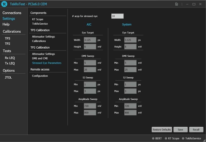
Figure 13. Configuring number of waveform averaging for stressed eye.
If the RX software cannot find a converging set of variable stresses after sweeping all available parameters, the user may take several actions:
- Change ISI lane pairs to reduce channel loss by 0.5 dB. This will require a re-run of TP2 calibrations with reduced channel loss.
- In the case of changing the ISI pair, the user should rerun the two steps that are dependent on the ISI pair: the Preset Selection, and the Stressed Eye Cal. These should be rerun to 1) find the optimal Preset and CTLE based on the current ISI pair, and 2) find the final stress recipe based on the current ISI pair.
Consider using manual sweep settings while holding other variables constant. An addendum will be added to this document providing guidance on how best to use sweep mode in this case.
TP2 Calibration Time
TP2 calibration takes two and a half to four hours to run using standard software settings. This run time is affected by several factors including:
- Is IL Verification step run, or is VNA data used?
- Is ISI channel loss within target range?
- Can convergence be obtained with combination of BERT variable stresses and ISI channel loss?
- Variable stress sweep settings (Min, Max, granularity).
- Run modes (explained in the following section).
The user has several controls to enable successful completion of Stressed Eye Cal including:
- Standard mode: This is the default and recommended run mode for Stressed Eye Cal. Preset and CMI/DMI stresses are enabled, and BERT step response is captured and averaged, then passed to Seasim for analysis. This process is repeated multiple times while sweeping stresses in the allowable range. Seasim computes eye width and eye height, and TekRXTest software computes eye area then checks for convergence. A linear sweep of stresses (amplitude, SJ, DMI) is performed to close the calibration.
- Manual mode: Allows the user to manually enter SJ, DMI and amplitude values for Stressed Eye Cal. This mode is valuable for “what-if” testing or debug to try discrete combinations of stresses for calibration closure.
- Exhaustive sweep mode: Allows the user to run Stressed Eye Cal for all combinations of amplitude, SJ and DMI within the sweep range with defined step sizes. The user controls sweep ranges and step sizes as shown in Figure 14. The wider the range and smaller the step size, the longer the run will take. This sweep will not stop when a converged eye is found, rather it will perform a complete sweep of parameters and ranges defined by the user. The user may stop the sweep prior to completion. If the user sees a combination of stresses that is desired then enable manual mode and perform stressed eye verification with these settings to test for convergence.
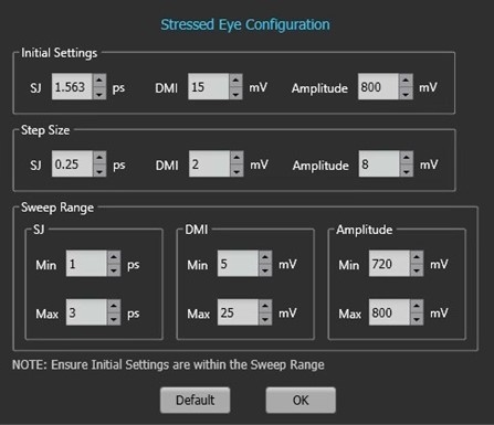
Figure 14. User can control sweep ranges and step sizes.
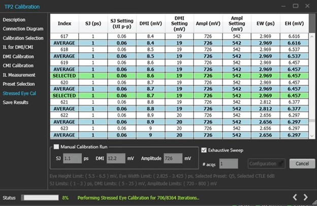
TekRXTest software will iterate and adjust stresses until it finds a combination that results in an averaged eye width and eye height within the target range. In the example shown in Figure 15, a successfully converged stress calibration is shown in the green rows. In this example, averaged eye width = 2.929 ps and averaged eye height = 6.657 mV. These results were achieved using preset Q5, CTLE = 6 dB, amplitude = 726 mV, SJ = 1 ps, and DMI = 8.7 mV.
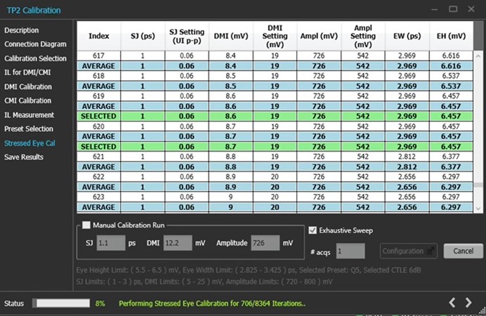
Figure 15. Green rows show an example of a successfully converged stress calibration.
BERT Stress Calibration Best Practices
Before running BERT stress calibration, the user should ensure the following prerequisites are met to maximize accuracy and repeatability:
- Ensure scope and BERT have been powered on for ≥30 minutes. This ensures instruments are warmed up prior to calibration.
- Ensure scope is running the latest versions of TekScope and waveform analysis software. To verify latest software versions, please contact your local Tektronix field application engineer.
- On the scope with all RF cables disconnected, run signal path compensation (SPC) under UTLITITES ➞ INTRUMENT CALIBRATION. SPC is recommended once every 30 days or if ambient temperature changes by >5 degrees C.
- Characterize PCIe 6.0 CEM fixture loss with VNA for TP2 ISI pair combination. For System Host, ISI trace pairs + RF cables should measure ~24 dB loss @ 16 GHz (Add-in Card ~28 dB loss @ 16 GHz). Refer to PCIe 6.0 PHY Test Spec, Appendix C for more details.
The goal of BERT stress calibration is to find a combination of four adjustable stress parameters (ISI channel loss, SJ, DMI, amplitude) when combined with fixed stressors (i.e. RJ, CMI) that yields averaged eye height and eye width values within the specified range. These target ranges are:
- Eye width: 2.825 ps to 3.425 ps (nominally 3.125 ps).
- Eye height: 5.5 mV to 6.5 mV (nominally 6 mV).
The PCIe 6.0 PHY Test Specification specifies BERT stress calibration flow as follows:
- Start with maximum ISI channel of 33 dB (HW ISI channel loss + embedded package model) for capturing the step response.
- Post process BERT step response with Seasim to find optimal preset and CTLE.
- Post process BERT step response with Seasim to sweep adjustable parameters.
- If a converged solution can be found, the calibration is successful. Record these values.
- If no solution can be found with any combination of SJ, DMI, and amplitude, reduce ISI channel loss by one pair (nominally 0.5 dB step).
- Repeat steps two through five until a solution converges within target eye width and eye height ranges.
VNA characterization of PCIe 6.0 fixtures along with RF cables is highly recommended prior to running BERT stress calibration. TekRXTest software does provide a step-response based ISI channel verification, but this value may deviate from a VNA-based measurement by several dB. The goal is to find a combination of ISI channel + RF cable loss that is ~24 dB @ 16 GHz for System Host, ~28 dB @ 16 GHz for Add-in card. Once the ISI channel + RF cable combination is found, this is the starting point for the TP2 portion of the calibration.
Troubleshooting
In cases where TekRXTest does not successfully provide a converged BERT stress calibration at the end of TP2, below are several areas to assess what changes should be made in the test setup or calibration settings:
- Check software revisions (scope, BERT, Sigtest, Seasim, etc.).
- Perform scope self-test and signal path compensation.
- Ensure scope channels are correctly deskewed <1 ps.
- Ensure coaxial connections in the signal path are tight and torqued to the proper value where appropriate.
- With no signal applied, measure pk-pk ACrms voltage on scope ATI Channel 1 and Channel 2 using auto measurements. This ACrms value should be in the range of 1.1 to 1.3 mV. The measured ACrms mean value should also match between Channel 1 and Channel 2 within a tight tolerance (≤.3 mV). If either condition is not met, ensure proper airflow into and out of the scope to provide proper cooling. A minimum six-inch clearance is recommended on all sides of the scope. Ensure instruments sitting in close proximity to the scope are not blowing hot air into the scope air inlet located on the bottom of each scope unit.
Your Tektronix field application engineer is standing by to assist you. If you have followed this guide and are still not achieving convergence during BERT stress calibration, reach out to your local Tektronix application engineer for assistance.