Introduction
With data and transmission speeds increasing, faster test generator requirements are also increasing. With AWG (Arbitrary Waveform Generator) sample rates and max freq.response now available up to 50GS/s and 20GHz respectively,engineers can now finally test many designs that were only simulations before. The newest test challenges are pushing the limits on these test equipment capabilities. Applications such as Coherent Optical Transmission with up to 30GB/s rates and long haul optical data transmission, with rates up to 1.5Tb/s, require the fastest sample rates available. Not only that, but these capabilities require multiple channels to support IQ modulation techniques.
With the introduction of the Tektronix AWG70001A and its 50 GS/s single channel capability, engineers are looking to combine two or more of these units to fulfill these challenging requirements. Not only do they need multiple channels at these rates, but the units must also be synchronized to each other and be able to output coherent signals totally synchronized.
This guide will walk you through the recommended method of synchronization.
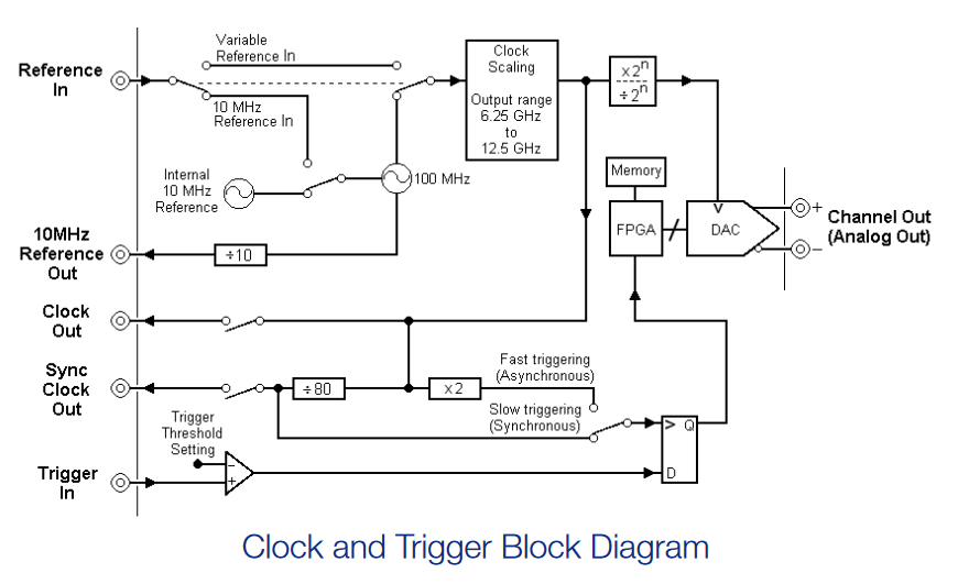
AWG Clocking and Triggering
In order to understand the best methods of synchronization first we need to familiarize ourselves with the AWG clocking and triggering. Notice in this diagram that when we use the slow triggering (Synchronous mode) the ref clock is still divided by 80 (the same as the Sync Out).
Async and Sync Timing
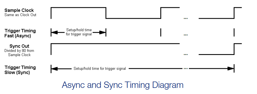
As you can see in this diagram, using the Slow Sync mode allows for a much wider trigger sample and hold area to allow for easier trigger synchronization.
Alignment Between Instruments is a Three Step Process
- First we need to set the instruments up with a common clock reference and the same sample rate.
- It is best to use a higher frequency reference rather than 10 MHz to minimize jitter between channels.The Variable reference input accepts signals between 35 and 250 MHz.
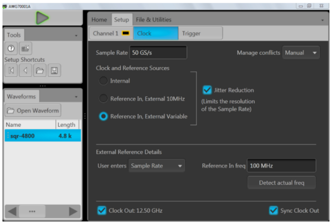
- The sample rate must be an integer multiple of the divided reference in the clock circuit. The easiest way to insure this is to select the "Jitter Reduction" mode in the clock menu. (The reference circuit divides the variable reference by 1,2 or 4 to insure an internal frequency between 35 MHz and 70MHz)
- To start waveforms at the same time the multiple AWGs can be triggered with a common external trigger.
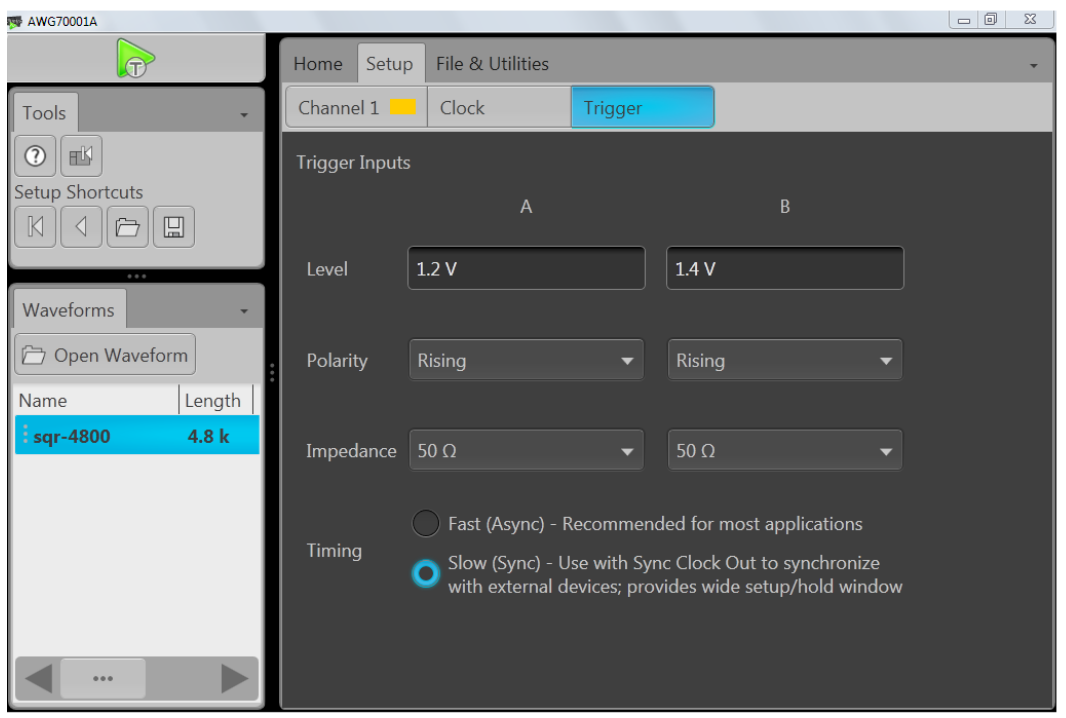
- The AWGs are set to synchronous trigger mode, which starts waveform output on a divided clock edge rather than a sample clock edge. This provides a wider setup and hold window trigger timing.
- The trigger should be synchronous with the internal divided clock for the most reliable triggering.
- The divided clock frequency is the clock frequency/80. So for an interleave sample rate of 50 GS/s, each DAC operates at 25 GS/s, the clock is at 12.5 GHz and the divided clock is 156.25 MHz. The Sync out clock on the back panel is a replica of the divided clock. It can be enabled in the clock menu.
- We need to generate a trigger from the 100MHz reference that is also synchronous with the divided clock. 156.25MHz/250KHz = 625 (an Integer) and 100MHz/250KHz = 400 (also an integer). So 250 KHz will work. It might be better to use a lower rate like 50 KHz with a short pulse so there is a smaller chance of pushing output on button during the high part of the trigger pulse. Note:
- In order to guarantee synchronization the trigger rate needs to be a multiple of the /80 clock. So trigger rate needs to be a divide rate that works for both the reference clock and /80 clock.
- It is also recommended to reduce the duty cycle of the trigger pulse to around a 30 ns high time along with the 50KHz rate which is really what will reduce the probability of turning on the AFG during a high pulse on the trigger.
- We can set up an AFG to provide the 100MHz reference from one channel and a synchronous 50 KHz output from the second channel. Then we manually switch the 50 KHz on and off to enable the trigger.
- It is useful to observe the Sync Out clocks of the AWG’s, but because of the skew from the divided clock to the analog output, the Sync Out clocks of the AWGs might not line up when the outputs are aligned. For a given sample rate, however, the timing relationship is stable. Triggering occurs on the positive half cycle of the Sync Out clock, so it might be necessary to use different length cables in the trigger paths to trigger on the same cycle.
- The delay of the trigger relative to the reference might need an experimental adjustment to get reliable setup and hold timing.
- When the AWGs start up, the internal divided clocks start with a random phase relative to one another. As a result, the outputs need to be aligned each time the sample rate is changed or the clock is stopped. In addition, there is timing skew from this divided clock to the output that is unique to each instrument.
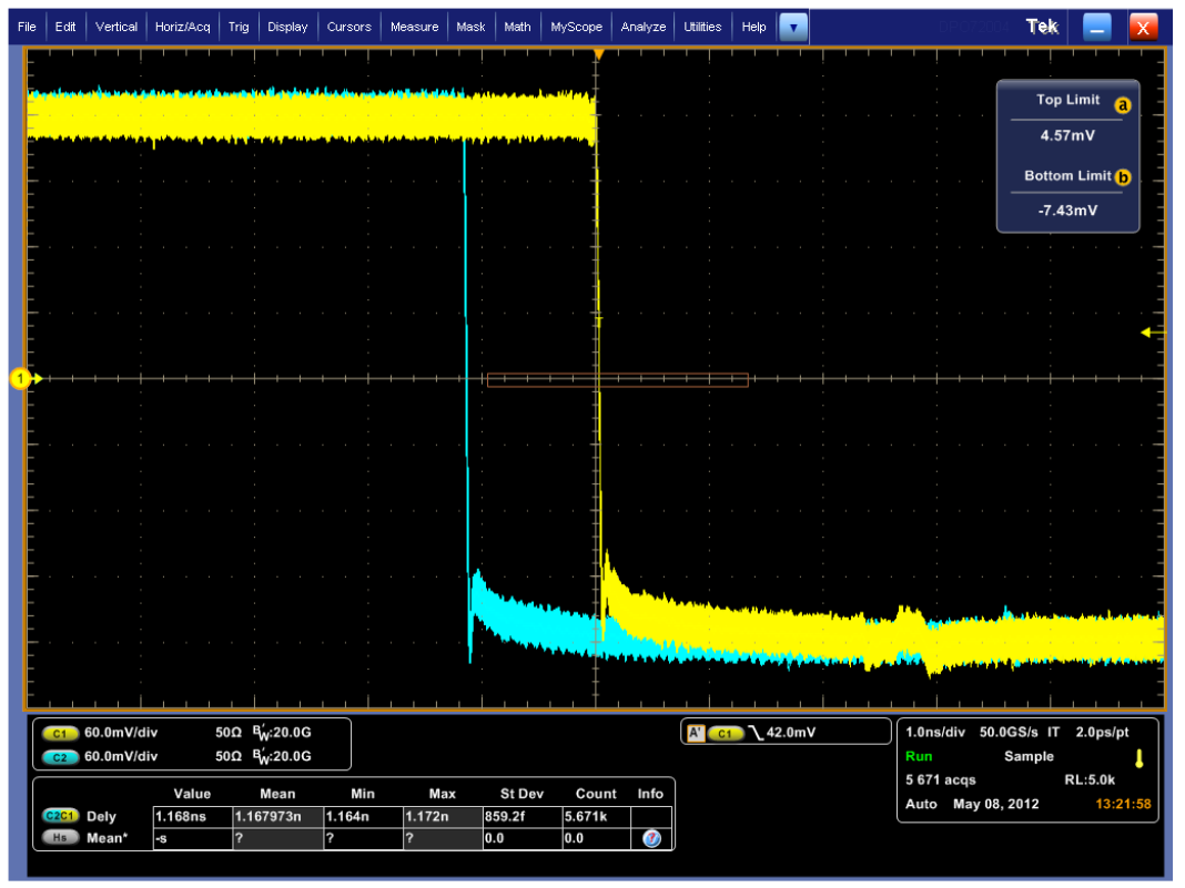
- Alignment is accomplished by observing the output signal or marker from each AWG and adjusting the clock phase until they line up.
- This is where there is an element of random chance in the setup. If the initial startup is too far out of alignment (> 2ns) then there will not be enough range to adjust the phase of one AWG to line up with the other. In this case you need to force the clocks to start again until a reasonable starting condition is achieved. This can be done by switching to Internal Reference and back to External in the Setup/Clock menu. Restart both AWGs if necessary. Experiment with this while observing the AWG outputs and the Sync Out clocks. The outputs need to start out less than 2ns apart to be within range of alignment.
Instrument Setups
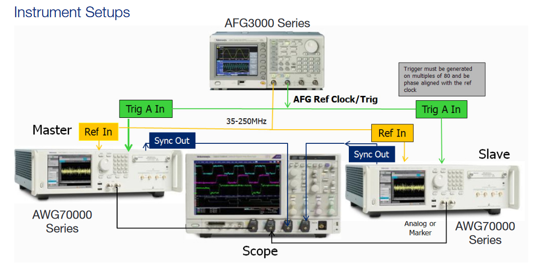
Recommended Equipment:
2) AWG70Ks
This method will also work with more than 2 AWGs, although care will have to be taken to match cable delays.
1) AFG3252
1) High BW scope >= DPO70804C
2) 103-0030-00 - BNC "T" connectors
4) 015-1018-00 - SMA Male to BNC Female adapter
4) 012-0076-00 - 18 in., male-to-male BNC cables
4) 174-5771-00 - 38 in. male-to-male precision SMA cables
AFG3000 Series Setup
- Set AFG Ch1 to 100MHz sine wave, 5vp-p, Continuous
- Set AFG Ch2 to pulse 50KHz, width 100ns, 5v High 0 low, Continuous
- Ch1 on
- Ch2 off (this will be used as a manual trig later)
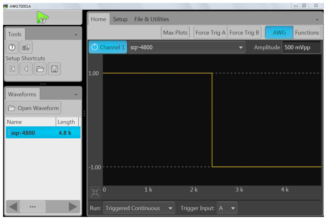
AWG70001A Setup
- If using AWG70001As, load a 4800 point square wave into CH1 of both instruments. If using AWG70002As, load a 2400 point square wave into Ch1 of both instruments.
- From the Home menu select Trigger input to Trig A , Run Mode Triggered Continuous
- It may be useful to set the Run mode to Triggered, this will allow real time output phase adjustment while watching signals on the scope.
- Using the Trigger Continuous Run mode once everything is setup would give best performance since the AWGs only wait for one trigger and then run the waveforms continuous.
- From the setup clock menu set both AWGs to use Variable Ref Clock
- Set Manage conflicts set to Manual.
- Make sure to set AWGs to Jitter Reduction Mode
- Make sure the Reference in Freq locks to the 100MHz Ref when selecting Detect actual freq.
- Set Sample Rate to 50GS/s
- Select Sync Out (this turns on the sync output)
- In the Trigger menu, Set Trigger A to 1.2V, Rising, 50ohms.
- Select Timing Slow (Sync)
- . Make sure AWGs are waiting for a Trigger by toggling the Play button making sure it is yellow.
Aligning Output
- Turn on Ch2 of AFG
- Both AWGs Play icon should turn green
- If the analog and sync signals being observed on the scope are > 2ns apart this step will have to be repeated.
- Turn off Ch2 of AFG.
- Set AWG clock to Internal and back to External Reference.
- Turn on AFG ch2 again.
- Once the outputs are within adjustment range.
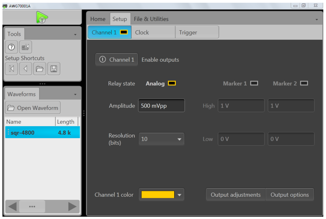
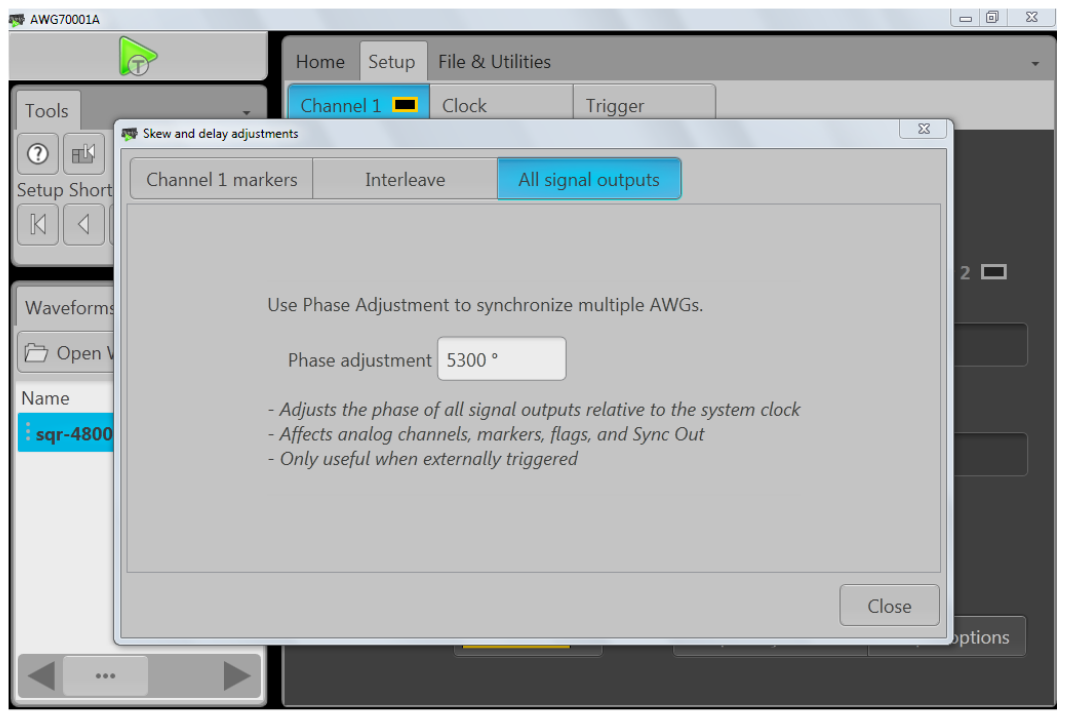
- In Setup Channel menu select Output Adjustments
- Then select the All Signal Outputs tab
- Adjust phase on slave unit until both AWGs ch1 line up on scope.
- Timing between AWGs: The All signal outputs phase can be adjusted and any time for fine timing alignment.
- Interleave timing: In the AWG70001A at sample rates above 25 GS/s, timing between the two interleaved DACs can be adjusted as well as the amplitude balance. The control is in the Setup/Channel tab. Click the Output adjustments button.
Changing Waveforms in AWGs
- In order to change the waveform without losing the sync timing you need to first turn off ch2 of the AFG to remove the trigger.
- Change to new waveform making sure that the Sample Rate is not changed.
- Check that the AWGs run button is yellow making sure the AWG’s triggers are armed. If not Re-arm the triggers on both AWGs by pushing the Run button.
- Turn the AFG Ch2 on to send a new trigger to start the waveforms.
Conclusion
- With the AWG70001A sample rates as high as 50GS/s and output frequency responses as high as 20GHz.Engineers can now test circuits that were not easily tested before.
- Many of these applications require more than a single output capability.
- The AWG70000 series can be synchronized with minimum trigger uncertainty and phase delays to allow multiple high data rate outputs.