
Introduction
Transmission links using microwave radio fill an important role in the infrastructure strategy of many network operators. Although eclipsed in terms of link numbers and traffic capacity by fibre-optic systems, they can offer distinct advantages over other systems. For example they provide:
- Cost-effective transmission links over rugged terrain and harsh environments
- Fast deployment over a wide area when needed by a new operator
- Higher security since equipment can be more physically concentrated
This makes microwave technology attractive in many areas of the world from less-densely populated countries with a developing telecommunication infrastructure to highly-developed telecommunication networks in difficult terrain such as mountainous areas.
As SDH (Synchronous Digital Hierarchy) has become the international standard for telecommunications network infrastructure, so microwave radio links are being adapted to carry the new data formats. Radio equipment manufacturers are providing SDH interfaces to their radio relay terminals at several different bit-rates:
- STM-0 (52 Mbit/s) a reduced capacity SDH signal
- STM-1 (155 Mbit/s) the standard SDH signal
- STM-4 (622 Mbit/s) a 4x multiplex of STM-1, providing very high capacity
Most digital radio system manufacturers already have, or are developing, equipment based on these rates to suit their customers' differing requirements. In particular, the STM-0 (also known as STM-RR) signal gives substantial savings in cost, radio spectrum usage, modulation complexity, and power consumption.
SDH Radio Recommendations
A number of new international recommendations have recently been published to ensure that radio systems are designed to meet open SDH interface specifications so that interworking can be easily achieved between different terminal and multiplexer manufacturers.
It's important to recognise that this standardization doesn't extend to the air interface (unlike fibre-optic equivalent systems) due to the complexity of modulation schemes, diversity combining, coding methods, etc. The key recommendations are:
- ITU-R Rec. F.750-1 Architecture and functional aspects of radio-relay systems for SDH-based networks
- ITU-R Rec F.751-1 Transmission characteristics and performance requirements of radio-relay systems for SDH-based networks
- ITU-R Rec. F.1092 Error performance objectives for digital radio-relay systems which may form part of a 27,500 km hypothetical reference path
- ETSI DTR/TM-04021 SDH aspects regarding Digital Radio-Relay Systems
- ITU-T Rec. G.707 Network Node Interface for the Synchronous Digital Hierarchy (SDH)
The information which follows deals with the SDH Radio signal structure, its management overhead, the testing methodology, and concludes with a case study from NTL in the United Kingdom.
SDH Digital Radio Signal Structure
SDH (Synchronous Digital Hierarchy) has been designed to accommodate the plethora of existing and future data transmission methods and to provide a standard method of transporting any type of bulk data traffic around the world.
It's expected to be the public data transport system for the next 20 to 30 years and has been standardised worldwide by the ITU-T organisation through openly published recommendations. The latest revision of ITU-T Rec. G.707 fully describes the signal format and multiplexing structures used in SDH.
SDH Basics. How does the SDH network transport data? A digital communications channel whether voice, computer data, or video is surrounded by management overhead information, mapped into a virtual container (VC), and added onto a high-speed synchronous data stream as a payload with many other VCs. A pointer mechanism keeps track of where the VCs start in the SDH data stream so that the original channel can be simply dropped out of the SDH stream or cross-connected in a single operation. This "add-drop-multiplex" (ADMUX) function is a basic building block of SDH networks.
Current plesiochronous, or PDH, networks need several stages of mux and demux because the data channels and higher-order multiplexed channels run asynchronously. To accommodate the varying bit-rates, random bit-stuffing is used. This mechanism makes it difficult for today's customer-responsive operators to achieve the provisioning flexibility they need to satisfy increasingly demanding customers.
SDH Networks. Normally transmitted on fibre optics, the basic transmission rate is 155.52 Mbit/s (identified as STM-1) which can be multiplexed to form STM-4 (622.08 Mbit/s) and then STM-16 (2.488 Gbit/s) rates. STM-16 is typically still used for high-capacity point-to-point links while STM-1 can provide users direct access to high bandwidth services, such as 2 Mbit/s, in new network structures such as rings.
Since 1993, network operators worldwide have been moving rapidly to install SDH equipment in their networks. It brings benefits of service flexibility due to the built-in management overhead, lower cost since less multiplex equipment is needed, and higher availability since the network can be reconfigured and provisioned very quickly.
 |
| Figure 1. Basic STM-1 Serial data stream is conventionally viewed as a frame of data. |
SDH Multiplexing Structure. The basic STM-1 serial data stream is conventionally viewed as a frame of data (Figure 1). The management overhead, both regenerator section and multiplex section, is clearly delineated from the payload area which is free to carry many different data structures or VCs. The AU pointer is used to accommodate any phase differences between the payload and the SDH frame itself by identifying the starting byte of the VC.
The complete SDH multiplexing structure is shown in Figure 2. In order to accommodate the new STM-0 (STM-RR) 51.84 Mbit/s data rate, two new multiplex routes have been defined as indicated.
 |
| Figure 2. SDH multiplexing structure. |
In order to accomplish interconnection of STM-1 and STM-0 systems, three methods have been defined in ITU-R F.750-1:
- STM-1 using AU-4 payload carrying a TUG-3 multiplex structure
- STM-1 using AU-4 payload carrying a TUG-3/TUG-2 multiplex structure
- STM-1 using AU-3 payload
SDH Radio Overhead
 |
| Figure 3. Standard SDH overhead functions (STM-1). |
Every SDH data stream carries embedded overhead information which is used to carry framing, management, error performance monitoring, and other information. We'll look at the standard SDH overhead functions first (Figure 3).
Regenerator Section Overhead (RSOH) Definitions. This part of the SDH frame contains overhead information that can be accessed at simple line regenerator elements (such as radio repeaters) within the network. This information is extracted from the incoming data stream and then rebuilt with new information ready for onward transmission into the next section. The functions of the various bytes are:
- A1, A2 Frame alignment word
- J0 Regenerator section trace (ex-C1)
- B1 Regenerator section block error monitoring (BIP-8)
- E1 Order wire channel (EOW) regenerator section (64 kbit/s)
- F1 User channel (64 kbit/s)
- D1-D3 Data communication channel (DCC), regenerator section (192 kbit/s)
Multiplex Section Overhead (MSOH) Definitions. A multiplex section of the SDH network is defined between two network elements which perform AU-level operations (such as cross-connect). This overhead passes transparently through regenerators. The byte definitions are:
- B2 Multiplex section block error monitoring (BIP-24)
- K1, K2 Automatic protection switching (APS) channel; K2 includes MS-AIS (Alarm Indication Signal) and MS-RDI (Remote Defect Indication) alarm bits
- D4-D12 DCC for multiplex section (576 kbit/s)
- S1 Synchronisation status messages (SSMB)
- M1 Multiplex section Remote Error Indication (MS-REI)
- E2 Order-wire channel (EOW) multiplex section (64 kbit/s)
 |
| Figure 4. Path overhead functions (VC-4). |
Path Overhead (POH) Definitions. An SDH path is defined from end-to-end across a network. Path overhead allows tracing of a circuit across a network, while the path performance can be monitored end-to-end. Path overhead is attached to a Virtual Container when it enters the SDH network (Figure 4). The various byte definitions are:
- J1 Path trace for High Order Path Access Point Identifier
- B3 Path block error monitoring (BIP-8)
- C2 Signal label for payload identification
- G1 Path status; includes HP-REI (Remote Error Indication) and HP-RDI (Remote Defect Indication) bits
- F2, F3 Path user channels
- H4 Position indicator, e.g., for multiframe synchronisation
- K3 APS for protection at higher order path level
- N1 Network operator byte; allocated for Tandem Connection Monitoring (TCM) function
 |
| Figure 5. Overhead in STM-0 frame structure. |
Overhead in STM-0 51.84 Mbit/s Digital Sections. When using a STM-0 frame structure, only one-third the overhead capacity is available, so the bytes have to be re-structured (Figure 5). However, the byte definitions are exactly the same. Incoming SDH overhead is broken apart at the multiplexer just prior to the STM-0 terminal and the new STM-0 overhead assembled to provide control and monitoring over the SDH radio link.
Media-specific Functions (ref. F.751-1). Radio propagation is an inherently less well-controlled environment than optical fibre. As a result, several functions have been identified that require additional communication channels. Examples are:
- Early-warning radio protection switch activation
- Automatic transmitter power control (ATPC)
- Radio protection switching information and control
- Propagation monitoring
- Wayside traffic, auxiliary maintenance, and monitoring
- Forward error correction techniques are currently under study
Using STM-1 systems, part of the SDH overhead can be used to carry this information. At the STM-0 51.84 Mbit/s rate, this could be carried in an auxiliary channel.
SDH Radio Testing
There are three main categories of SDH network test:
- Connectivity Have the cables been assigned correctly and has the network been provisioned properly?
- Transmission Quality Does the system run error-free and are the network elements correctly synchronised?
- Fault Tolerance How does the network respond to alarm situations, tributary frequency offset, etc.
These are all used during the various activities of:
- Equipment installation
- System commissioning
- Network maintenance
- Problem troubleshooting
Let's look at two fundamental tests that are performed on SDH Digital Radio Systems during the commissioning phase of a new network payload and synchronisation testing.
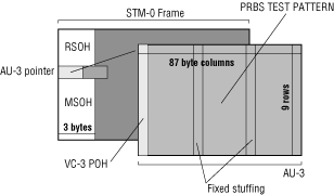 |
| Figure 6. STM-0/AU-3 payload with bulk-fill PRBS test pattern. |
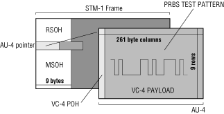 |
| Figure 7. STM-1/AU-4 payload with bulk-fill PRBS test pattern. |
Payload Testing. The purpose of payload testing is to ensure that the radio link is ready to carry a fully structured SDH signal with whatever payload may be provisioned into that SDH signal. The basic procedure is to test the entire payload capacity for bit errors. By looking at the Multiplex Structure of an SDH signal for radio, we can see that there are two basic test signals that need to be provided (see Figures 6 and 7):
- STM-1 with AU-4 test payload at 155 Mbit/s
- STM-0 with AU-3 test payload at 52 Mbit/s
NOTE: STM-1 with AU-3 payload is the North American SONET STS-1 signal type.
The quickest and most reliable method of ensuring the quality of the radio transmission path is to directly test the full payload capacity. This is done by applying a bulk-fill test pattern in the AU-4 and AU-3 payload structures. A PRBS test pattern is generated, mapped into the payload, and routed into the network through as many elements as are needed, typically looping back to the same test set. Any bit errors are monitored and analysed according to ITU-T Recommendation G.826.
Because this type of "equipped, unstructured" test signal is compatible with all network elements, it's sometimes known as a "clear-channel" test. Network elements simply pass the payload through, irrespective of how they have been provisioned as add-drop-multiplexers, for example. The result is a very fast test of the entire SDH payload capacity.
Synchronisation Testing. The purpose of synchronisation testing is to ensure that the network, as a whole, is operating correctly and that timing sources and clock routing are configured properly. Despite its name, SDH may not be completely synchronous due to several factors:
- Multiple clock sources, operating at different tolerances will be present in the network
- Jitter and, more significantly, low-frequency wander is present on synchronisation sources
- Payloads will be cross-connected from one synchronised path to another, synchronised from a different clock source
- Network elements may dynamically and autonomously change their synchronisation source, depending on particular quality criteria or fault conditions
Often, the first symptom that something is amiss is excessive jitter when the SDH payload is de-mapped from the network for example, if a 140 Mbit/s PDH tributary has been transported across an SDH network. Alternatively, SDH synchronisation problems may even cause frame slips on 2 Mbit/s tributaries.
The mechanism at work within the SDH network is pointer justification. Pointer justifications are designed to accommodate phase differences and frequency variations between the SDH transport frames and their payloads by quantising phase changes within the network thereby ensuring that no payload data is lost.
The most straightforward way to ensure that network synchronisation is working within tolerance is to directly monitor pointer movements over an extended period of time. This gives assurance that the stability of the network under normal operating conditions is within bounds.
SDH Radio Test Configurations. Testing may be done in two phases:
 |
| Figure 8. Production test of the modulator/demodulator terminal function. |
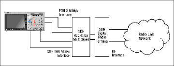 |
| Figure 9. Field test of the complete radio terminal plus SDH ADMUX. |
- The SDH radio terminal equipment (Figure 8). The example configuration shows a production test of the modulator/demodulator terminal function.
- The SDH multiplex equipment with the terminal (Figure 9). The example configuration shows a field test of the complete radio terminal plus an SDH ADMUX.
Both configurations would be tested during production in the factory and during commissioning in the field. The two phase, or "layered testing," allows for quicker fault localisation since the multiplex equipment is only tested once the terminal equipment has itself been verified.
- SDH Radio Terminal. The performance of the modulator/demodulator needs to be determined, either using a fading simulator (in the factory) or using a real RF link (in the field). The Tektronix CTS 750 Test Set generates the bulk-fill AU-3/STM-0 or AU-4/STM-1 signal required by the modulator, and analyses the signal after demodulation. The quality of the "clear channel" can be quickly determined in just one test and there is no need to run several tests consisting of different PDH payloads.
- SDH Multiplexer. A further suite of tests can be made when the access multiplexer is added. The test set now simulates the network to which the radio relay will be connected. Provisioning of the multiplexer can be tested, error testing across any of the supported multiplex paths and stability tests involving frequency offsets can be undertaken.
Choosing SDH Test Equipment. Since SDH radio links have their own specific test requirements, it's important to select the right level of test equipment with the capabilities that are most applicable to this application. Following is a listing of the more important test functions that are required:
- Support for AU-4 mapping at STM-1, AU-3 mapping at STM-0 with the relevant physical interface (G.703 CMI at STM-1, B3ZS at STM-0)
- Bulk AU-4 and AU-3 payload bit error testing allows direct testing of the full capacity of the radio terminals, without regard to the type of traffic payload that will be carried
- An error pulse output, triggered from error events in the SDH payload, can be used to trigger external equipment for fading analysis, or it can be connected directly to a fading simulator for stress testing
- Full access (read and write) to all levels of SDH overhead bytes is mandatory to allow easy path tracing, to quickly diagnose any equipment incompatibility, and to understand operation of the SDH layer
- Graphical display with interactive cursors, zoom, etc., is invaluable for diagnosing trends, analysing alarm/fault correlation, etc.
- Logging to memory and storage to disk are vital for performing long-term stability tests storage of one month of continuous testing results is a good benchmark
- Synchronisation wander is an important parameter to track, so SDH pointer events need to be monitored and displayed in graphical format.
- What are the network's safe operating conditions? Pointer sequence tests conforming to ITU-T Recommendation G.783 allow you to determine the response of your network to pointer stresses
Summary of SDH Radio Testing. SDH digital radio systems have their own special architectures and performance characteristics, so they need special facilities in test equipment to allow testing to be carried out efficiently and productively. At the same time, testing must be fully integrated with methodology normally used in conventional SDH systems. A test set such as the Tektronix CTS 750 SDH/PDH Test Set enables SDH radio system manufacturers, installers, and operators to take full advantage of rapid testing developments in the optical SDH network.
SDH Testing At NTL
The Tektronix CTS 750 Test Set is being used to test Europe's first interlocked ring network using SDH over microwave radio links across the United Kingdom. This nation-wide broadband network was brought on-line in September 1994 by NTL the company formed from the engineering division of the former Independent Broadcasting Authority (IBA) to run independent broadcast transmissions and communications services.
The NTL telecommunications network was developed to serve the needs of other national communications operators requiring multiple 2 Mbit/s circuits over major circuits between their switching centres. The nature of this type of operation requires guaranteed 100% round-the-clock availability. The corresponding requirements for reliable and accurate testing are vital as well.
Since it began to carry live traffic, the performance of the network has more than exceeded the stringent requirements placed on it due in large measure to the professionalism and commitment of the NTL organisation, backed by the world-renowned reputation for quality measurement equipment that Tektronix brings to the table.
SDH Network Technology. The use of SDH technology means that NTL is able to offer very high levels of flexibility, service and network resilience to the extent that bandwidth capacity can be called up at a moment's notice. The network is completely independent of other operators, and benefits from NTL's experience in the broadcast industry where guaranteed levels of uninterrupted availability are commonplace.
The essence of SDH is that it is a managed telecommunications infrastructure which packages the maximum amount of useable data with an efficient overhead channel for monitoring and management. Although developed to operate primarily over fibre-optic transmission links, SDH is equally applicable to microwave digital radio links.
The NTL system is based on 155 Mbit/s bearers, arranged in interlocking rings. Traffic travels around the rings in either direction, automatically giving service protection through route diversity. Signals are inserted or removed at special interface points called add-drop-multiplexers (ADMs), which allow flexible traffic access to and from the SDH transport.
Testing Requirements. As a newly-formed telecommunications operator, NTL wanted to get its system operational as quickly as possible. Testing procedures had to be implemented immediately as part of the commissioning process. In their search for suitable test equipment, NTL management decided that they needed something that was user-friendly and, above all, could be put to productive use with a minimum of operator training. The management also wanted a solution that was cost-effective, particularly in terms of capital outlay.
One option was to upgrade NTL's existing PDH (Plesiochronous Digital Hierarchy) test gear, but it proved more cost-effective to buy new, dedicated SDH test instruments. In fact, the Tektronix CTS 750 Test Set, which was the final choice, proved to be about 30% lower in cost than any alternative approach.
In addition, NTL ensured that it was ready for future network test requirements, since the CTS 750 can be readily upgraded to handle PDH traffic testing. Firmware can easily be upgraded via floppy disc a critical factor, since the network equipment itself is continually evolving to meet new service requirements and new international standards.
The CTS 750 SDH/PDH Test Set. The CTS 750 is a portable test set which is optimised for installation, commissioning, maintenance, and troubleshooting applications. It fulfills all the standard requirements for testing SDH optical systems and includes specific facilities for testing radio systems. In particular, it can carry out equipped bulk payload testing, as well as generating and monitoring SDH "pointer" movements critical for determining overall system synchronisation performance.
The CTS 750 allows users to verify network integrity quickly and easily, thereby ensuring a high availability of service. From NTL's point of view, it offered a solution to the company's needs, and one that could be delivered and become fully operational with a minimum of delay. Tektronix committed to deliver units within NTL's extremely tight project schedules and engineers were immediately able to start work in the field without needing a training course.
NTL's requirement for ease-of-use, and particularly the minimal amount of time allowed for staff training before the unit could be used productively, was certainly met by the CTS 750. It includes many user productivity features such as:
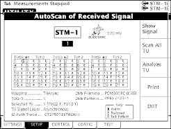 |
| Figure 10. AutoScan provides insight into SDH signal. |
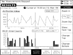 |
| Figure 11. Extensive use of graphics provides ease-of-use. |
- AutoScan automatically sets up the unit to suit the incoming signal and displays the graphical structure of the payload for immediate insight into network operation (see Figure 10)
- Extensive use of graphics, single-level menus, and an interactive user interface means that users can quickly start diagnosing problems in the network-under-test, rather than struggling with a complicated, difficult-to-use test set (see Figure 11)
- Standard PC-compatible floppy disk allows named "pass/fail" tests to be created, stored, and reliably executed in the field. As a result, a uniform test methodology can be created, with tests being set up centrally and deployed more widely in the field
The Test Process. The Tektronix CTS 750 Test Sets are used in the initial radio-link installation process, which is followed by commissioning over 24 hours and stability testing over an extended period of operation. Testing and link error analysis is performed according to ITU-T Recommendations G.826 and G.821 so that quality is guaranteed to accepted standards.
The transmission performance of the radio link itself can be tested using two CTS 750s, each located at transmitter stations which may be up to 50 miles apart. Each instrument generates a standard STM-1 155 Mbit/s structured test signal; the other instrument measures the received signal and pinpoints any problem areas. Alternatively, the test signal can be looped at the far end of the link and the same test set used to receive and analyse the signal. A clear graphical display gives an error profile of the link, indicates where errors are occurring, and analyses the errors in terms of the SDH data layer in which they occur.
Another series of tests is carried out to check the stability of the system by looking at factors such as drift, clock signals, voltage fluctuations, fading, noise, and EMC. Error performance is monitored, as are payload pointer movements. Network synchronisation is an increasingly important issue which operators need to address. Monitoring pointer movements gives insight into how clock information is transferred around the network.
The CTS 750 is also used for system stress testing which can take place at the commissioning stage or later. One example would be generating test signals with a frequency offset to ensure that the network can accommodate these, using the pointer justification process, and still operate correctly.
The Future
NTL also wanted an instrument which was future-proof in the sense that it could accommodate changes in standards, test requirements, and equipment capabilities. This is easily achieved with the CTS 750 by simply adding new plug-in cards. New software functionality or changes in SDH signal structure definitions can easily be incorporated via the floppy disk.
NTL has already upgraded its original SDH units with the PDH tributary test option which gives in-depth test and analysis of 2 Mbit/s circuits (the option also includes 34 and 140 Mbit/s as standard). A recent firmware upgrade demonstrates Tektronix' commitment to ensure that their customers remain up-to-date with constantly-evolving SDH technology.
For the future, the NTL engineers are looking to use the testers for other functions, including monitoring the 2 Mbit/s signals which carry their customers' traffic. Using the PDH tributary test option, parameters such as the Frame Alignment Word (FAW) and Cyclic Redundancy Check (CRC) are used to perform in-service monitoring on live traffic according to ITU-T Recommendation M.2100.
Satisfied With The Results
All in all, the managers and engineers at NTL are very satisfied with the cost-effective and productive nature of their CTS 750 Test Sets. A measure of the company's satisfaction can be seen by the fact that a further purchase quickly followed delivery of the initial units. NTL was also able to accommodate temporary peaks in demand due to commissioning deadlines by renting additional CTS 750 Test Sets during this critical period of time. A number of major UK rental companies recognise the unique capabilities and exceptional ease-of-use of the CTS 750 and have invested accordingly.
Conclusion
For operators who need to see what's going on inside their new SDH networks and ensure their network integrity, the Tektronix CTS 750 provides a flexible, up-to-date solution that delivers results rapidly with the highest operator productivity.
| 11/96 | 2GW-10684-0 |

