Introduction
Noise is a common and pervasive problem. Almost everyone involved with electrical circuits will spend some time dealing with noise - either finding its source to fix it or reducing its impact on measurements.
Noise can come from a virtually endless number of sources either internal or external to your design, obscuring your signal of interest. Perhaps you’re having trouble making measurements on a low voltage (mV) signal like in a radar transmission or heart monitor. Noise can make it difficult to find the true voltage of your signal, and it can increase jitter making timing measurements difficult. Or maybe you need a clean trace free from noise to focus on the intended signal in your design. Other times, a clean trace is useful for reports and documentation to clearly show how your design works.
Your oscilloscope provides features and tools to help you deal with noise. This application note will review common oscilloscope features to reduce noise during measurements, including an innovative tool available only on the Tektronix MSO2000 and DPO2000 Series Oscilloscopes. With the FilterVu™ variable low-pass filter, you can filter unwanted noise from your signal while still capturing unexpected glitches up to the full bandwidth of the oscilloscope, enabling you to focus on your signal of interest without missing critical high-frequency events.
Using Your Oscilloscope to Measure a Noisy Signal
Stable Triggers Required
Before you analyze your signal, you need a stable display which can be a problem if your signal is noisy, making it difficult to create a stable trigger. Most oscilloscopes come with several features that assist you with this problem.
Often, the first step in creating a stable trigger is to test which trigger coupling mode works best. Many Tektronix oscilloscopes offer high-frequency (HF) reject, low-frequency (LF) reject and noise reject trigger coupling options, each of which can be used to create a stable trigger for your signal.
HF Reject performs a low-pass filter on the trigger path, attempting to ignore any high frequency instability or noise. LF Reject performs a high-pass filter on the trigger path, attempting to exclude low frequency signals from causing triggers. Noise Reject increases the required trigger hysteresis, preventing random noise from causing triggers. It may be difficult to predict how these modes will affect your particular signal; try each one, if necessary, to attain a stable trigger.
Trigger systems in most oscilloscopes also offer a holdoff control. This control only allows triggers after a user-specified delay timer. Try adjusting the holdoff to ignore some false triggers if your signal is repetitive
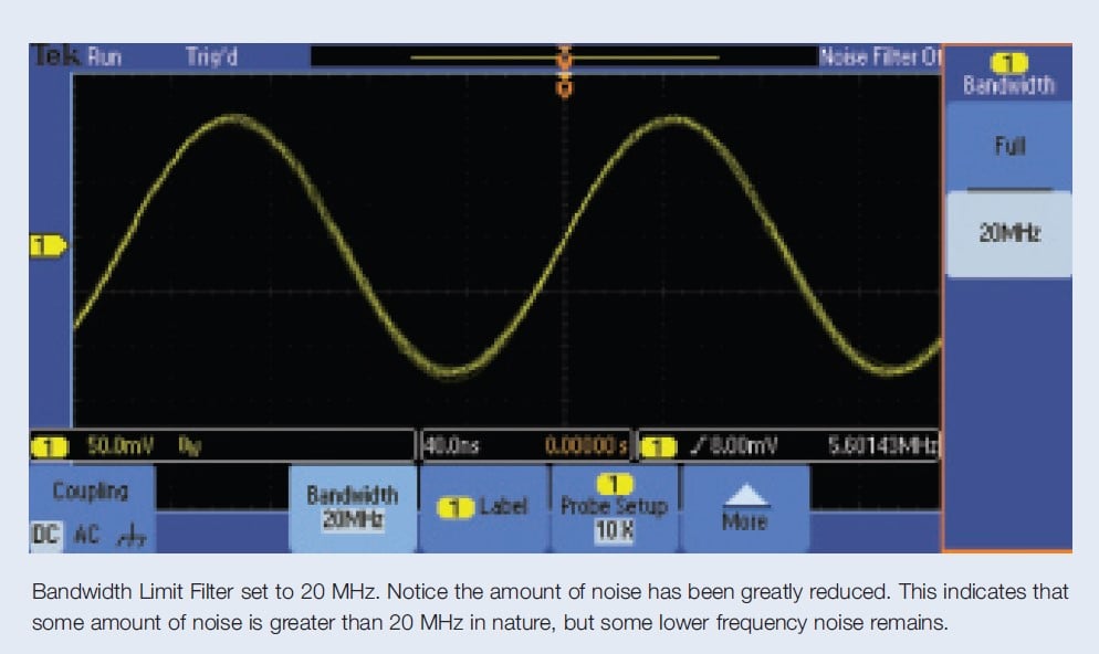
If triggers are still unstable, most oscilloscopes offer a Bandwidth Limit Filter that passes the signal through a low-pass filter. The low-pass filter typically has only a few frequency settings available and often goes no lower than 20 MHz. For many applications, such as debugging power supply issues, this may not be low enough. Try the different bandwidth settings until a stable trigger is achieved.
Reducing Noise on Your Displayed Signal
Once you have a stable trigger, you can further adjust the display of noise on your oscilloscope. There are several tools available to do this: Bandwidth Limit Filter (discussed above), Average Acquisition Mode, HiRes Acquisition Mode, and FilterVu Variable Low-pass Filter, a new feature available
on the Tektronix MSO/DPO2000 Series Oscilloscopes.
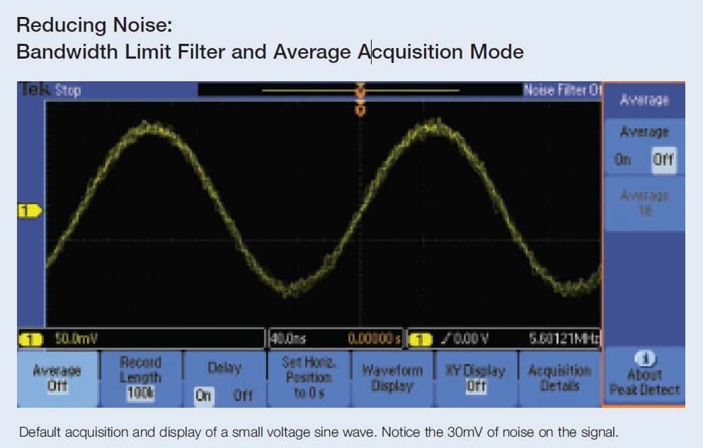
Bandwidth Limit Filter
The Bandwidth Limit Filter reduces the bandwidth of your oscilloscope to the frequency selected. This means that frequencies higher than the selected level will be attenuated or removed completely from the trigger path, as well as the acquisition and display path. The Bandwidth Limit Filter can be used not only for attaining a stable trigger, but also for reducing the amount of noise displayed on the oscilloscope.
Using the Bandwidth Limit Filter is one of the simplest ways to reduce noise in your oscilloscope, and works well if all the undesirable noise is at frequencies above the fixed cutoff. However, any high-speed glitches that may occur will also be removed.
Oscilloscopes typically offer a very limited set of bandwidth limit settings; standard selections include 250 MHz and 20 MHz.
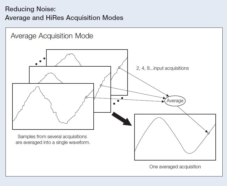
Average Acquisition Mode
Average Acquisition Mode takes several complete acquisitions and averages them point by point to obtain the average voltage at each time sample in the acquisition. The number of acquisitions included in the average is adjustable by the user. Noise is typically random from acquisition to acquisition, sometimes up and sometimes down. When these random variations are averaged over enough acquisitions, they will cancel out, creating a stable signal on the screen.To utilize Average Acquisition Mode, your waveform must be repetitive. Non- repetitive waveforms or single-shot events cannot be averaged.
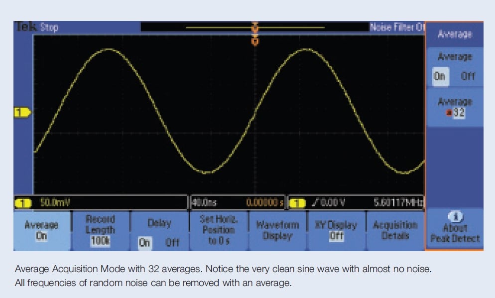
Average Acquisition Mode reduces all kinds of uncorrelated signals and random noise, even at very low frequencies.And, it works across all oscilloscope time/division settings.Since multiple waveforms must be acquired to create one averaged waveform, the display can be slow to update from a changing input signal or a front-panel knob change. This means infrequent glitches will likely be missed.In some applications, Average Acquisition Mode is a better choice than the Bandwidth Limit Filter since the full bandwidth of the oscilloscope is available to capture high frequency repetitive events.
HiRes Acquisition Mode
Some oscilloscopes include a HiRes Acquisition Mode which is similar to Average Acquisition Mode since it uses averaging to eliminate noise. HiRes Acquisition Mode performs a box car average on each acquisition, averaging several adjacent samples within a single acquired waveform to create a single averaged sample. This has the effect of reducing high frequency noise as the average will cancel out the high speed variance in voltages caused by the noise. It also reduces the sample rate because it converts many samples into one. Therefore, HiRes Acquisition Mode is only available at slower time/division settings where the oscilloscope still has sufficient sample rate to represent the measured signal.
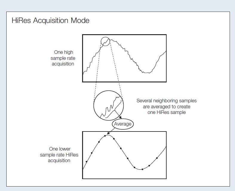
Unlike Average Acquisition Mode, HiRes Acquisition Mode can be used on non- repetitive and single-shot waveforms. And, since only one waveform needs to be acquired, HiRes Acquisition Mode provides a much faster update to the display after an input or front-panel setting change. The combining of neighboring samples in time also reduces the chance of aliasing at slower time/division settings.
Since HiRes Acquisition Mode is a type of low-pass filtering, you may miss high speed glitches on your signal. HiRes Acquisition Mode will pass some high frequency noise, which may obscure your signal shape and edge position.There is typically no indication of what frequencies, if any, are being removed in HiRes Acquisition Mode.HiRes Acquisition Mode may reduce some aliased frequencies from the display; other aliased frequencies may still be present due to the poor frequency-selectivity nature of the HiRes low-pass filter.
DSP Filters
Some oscilloscopes offer post-processing DSP filters which remove certain frequencies of noise from your signal. You have complete control over the filter frequency. While these filters may be flexible, they often are slow, suitable only for single-shot or slow update rate displays. They may filter out interesting and important glitches or anomalies without your knowledge.
FilterVu™ Variable Low-pass Filtering
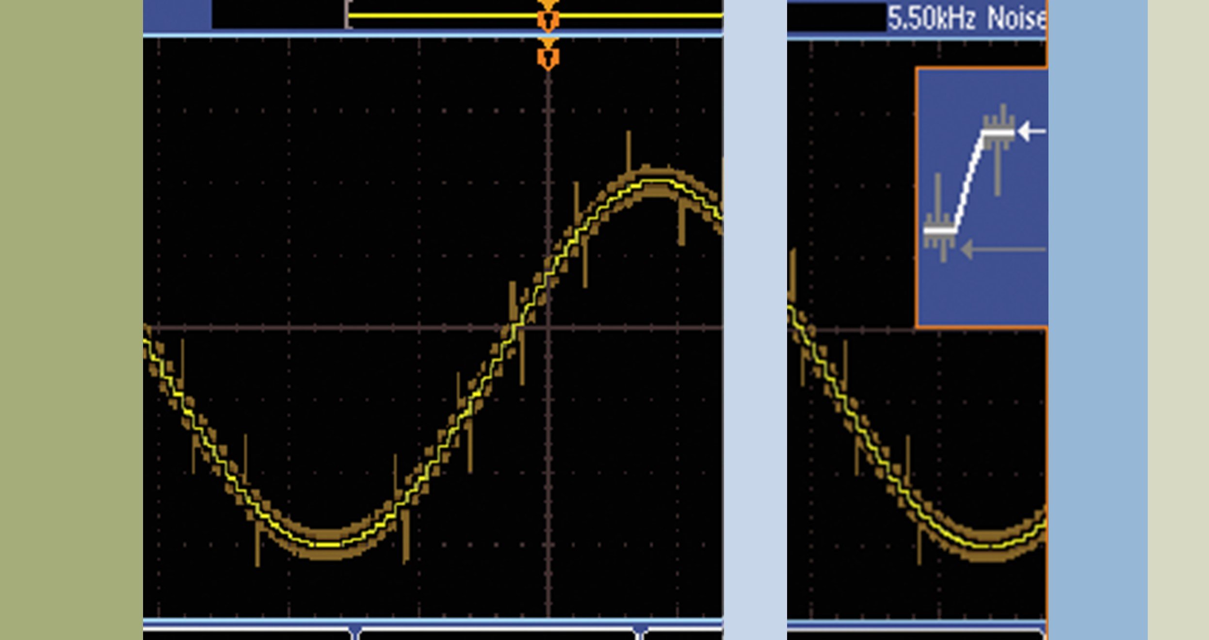
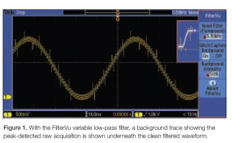
The Tektronix MSO/DPO2000 Series Oscilloscopes offer a powerful feature, FilterVu™ variable low-pass filtering, to help filter unwanted noise from your signal. FilterVu allows you to select a low-pass filter frequency to apply to the displayed acquisition. In addition to the low-pass filtered trace, you are protected from missing any unexpected high-frequency glitches or large magnitude noise by an unobtrusive back- ground trace showing the peak-detected (min/max sampled) raw acquisition underneath the clean filtered waveform (See Figure 1).
You can adjust the low-pass filter cutoff frequency from the front-panel, allowing you to control the amount of noise reduction you would like. Filter frequency readouts allow you to characterize what frequencies of noise are on your signal without the need to setup a cumbersome FFT (Fast Fourier Transform). This adjustment is available even on a single-shot waveform after acquisition, allowing careful inspection of your signal.
As part of the acquisition process, FilterVu offers the fast display update of HiRes Acquisition Mode with the flexibility and control of a post-processing DSP filter, while maintaining a background image to show high-frequency glitches and noise magnitude.The peak-detect background trace captures peak excursions of your signal up to the bandwidth of the oscilloscope, even on single-shot waveforms. This means that any glitch that can be captured at the fastest time/division setting will still be shown when inspecting your signal at the slowest time/ division setting.
Just as with HiRes Acquisition Mode, FilterVu™ filtering is not available at all time/division settings. As you change to faster settings, the range of the filter is reduced. At the fastest time/division settings, no filtering is available because the low-pass filter works by reducing the number of sample points in the wave- form. At many time/division settings, the oscilloscope runs at a reduced sample rate and there are many extra points. When the oscilloscope runs at or near its full sample rate, there are fewer extra points and the FilterVu functionality will be reduced. Average Acquisition Mode is the preferred choice for reducing noise at the fastest time/division settings.
FilterVu can be used on repetitive, non- repetitive, and single-shot waveforms. Its wide range of filter frequency adjustability allows you to remove just enough noise without rolling off your signal. Compared to the Bandwidth Limit Filter, FilterVu can filter to lower frequencies (less than 1 MHz), and unlike HiRes Acquisition Mode, it doesn't pass unwanted high frequencies that can obscure your signal. With its peak-detect background protecting you against missing important glitches, it is a great replacement for HiRes Acquisition Mode.
FilterVu can reduce the effects of aliasing. At the lowest available noise filter frequency at each time/division setting, no more than 1% of the high- frequency content that causes aliasing can pass through the filter when the frequency is set to the minimum, zoom is off, and acquisitions are running. Only the aliased frequencies are removed, not your signal of interest.
Conclusion
Noise is a pervasive and challenging problem in nearly all electrical design and debug work. In this application note, we have discussed some of the oscilloscope tools you can use to reduce, understand, and characterize noise in your measurements. FilterVu low-pass filter in the Tektronix MSO2000 and DPO2000 Series Oscilloscopes adds a powerful and flexible tool, with fewer compromises, enabling you to better address noise issues in your designs.
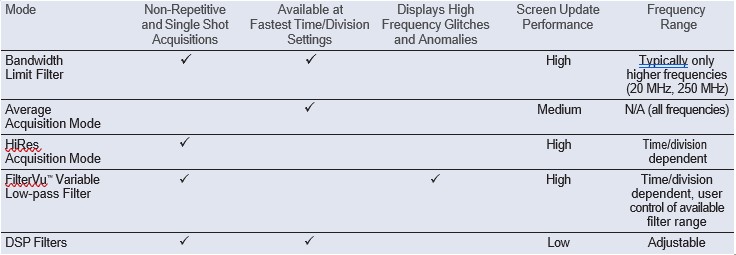
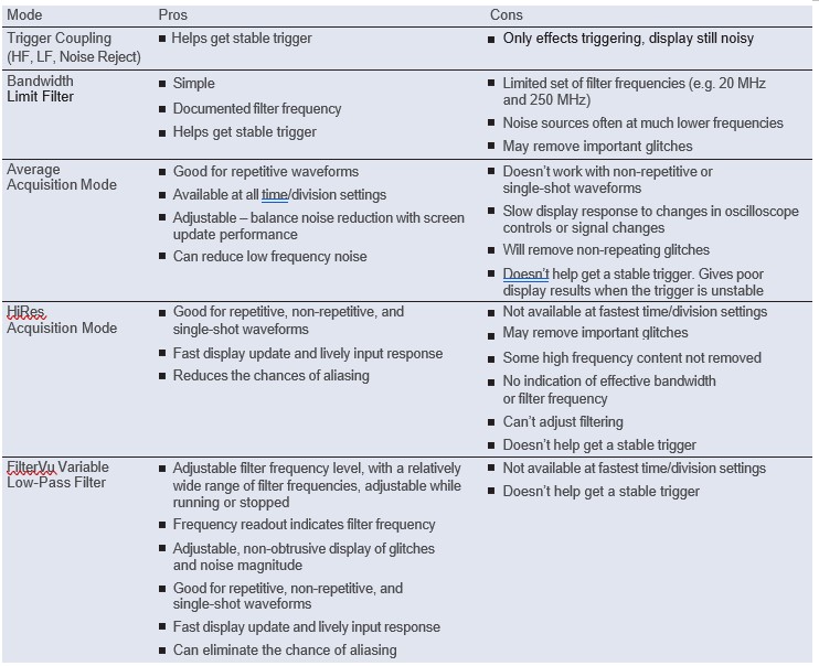
Comparison of Different Filters and Acquisition Modes