Contactez-nous
Chat en direct avec un représentant Tek. Service disponible de 9 h à 17 h, CET jours ouvrables.
Appelez-nous au
Disponible de 9 h à 17 h CET jours ouvrables.
Télécharger
Télécharger des manuels, des fiches techniques, des logiciels, etc. :
Feedback
TekExpress 400G Transmitter Test
Electrical Conformance and Characterization Solution for Real-Time Oscilloscopes
Plus d’informations
- Oscilloscope hautes performances DPO70000SX ATI
- Oscilloscopes au phosphore numérique et à signaux mixtes MSO/DPO70000DX
- Découvrez d'autres modèles Logiciel pour oscilloscopes, produits keithley, et RF
Lire en ligne :
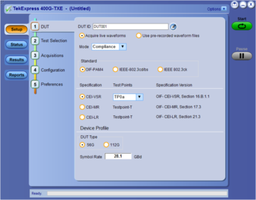
The new Tektronix real-time instrument based OIF-CEI-56G-VSR/MR/LR, OIF-CEI-112G-VSR, IEEE: 802.3bs (200GAUI-4 and 400GAUI-8), 802.3cd (CR4, KR4), 802.3ckTM (100GAUI-1, 200GAUI-2, and 400GAUI-4), and 802.3ckTM (100GCR-1, 200GCR-2, and 400GCR-4) Transmitter Characterization automation system provides turnkey testing and debugging of the industry's most common 400G PAMJET electrical interfaces. The silicon designers need to perform the 400G based electrical validation of their silicon; the system designers need to perform the 400G based electrical validation.
Key Features
- Offers streamlined and fully automated transmitter characterization of OIF-CEI-56G-VSR/MR/LR, OIF-CEI-112G-VSR, and IEEE: 802.3bs (200GAUI-4 and 400GAUI-8), 802.3cd (CR4, KR4), 802.3ckTM (100GAUI-1, 200GAUI-2, and 400GAUI-4), and 802.3ckTM (100GCR-1, 200GCR-2, and 400GCR-4) electrical transmitter specifications.
- Extends PAMJET software package (PAMJET software package) for in-depth analysis and debug of fully automated conformance test solution.
Applications
- Validation of OIF-CEI-56G-VSR/MR/LR, OIF-CEI-112G-VSR, and IEEE-802.3bs/cd standards
- Measurements of electrical transmitter :
- 802.3ckTM Electrical 100 Gb/s Signaling for 100GAUI-1, 200GAUI-2, and 400GAUI-4.
- 802.3ckTM (100GCR-1, 200GCR-2, and 400GCR-4)
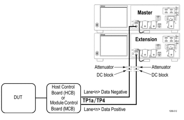
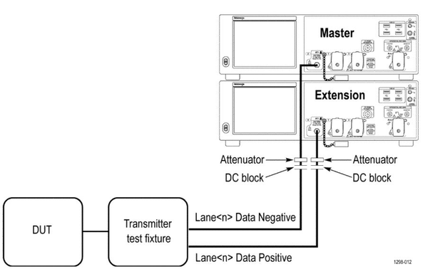
OIF-CEI-56G-VSR/MR/LR, OIF-CEI-112G-VSR, IEEE-802.3bs/cd, IEEE-802.3cK AUI and CR fully automated electrical transmitter real-time oscilloscope measurements
This application package is designed for a 50 GHz or higher, 70K SX instrument pair. For 100Gb/s/lane and faster the needed oscilloscope bandwidth ≥ 59 GHz 70k XS instrument pair is required; for 56 GBd and faster 70 GHz instrument will deliver the best results. The software loads the required roll-off filters with appropriate bandwidth. The low noise level of the ATI architecture serves the key signal-to-noise and distortion ratio measurements, which are attained with margin on the 70K SX systems. The solution is also available on non-70K SX systems, such as 33 GHz, higher 70K DX, and MSO instruments with an understanding that these are for debug only and not for the specification level conformance validation.
| Technology | Specification Section and Table reference |
|---|---|
| OIF-CEI-56G-VSR | oif2017.346.03, Sections 16.B, Table 16-10 |
| oif2017.346.03, Sections 16.3.2, Table 16-1 | |
| oif2017.346.03, Sections 16.3.3, Table 16-4 | |
| OIF-CEI-56G-MR | oif2014.245.12, section 17.3, Table 17-2, 17-3 |
| OIF-CEI-56G-LR | oif2014.340.08, section 21.3, Table 21-2, 21-3 |
| OIF-CEI-112G-VSR | oif2017.346.03, Table 23-9, Section 23.B.1.1 |
| oif2017.346.03, Table 23-1, Section 23.3.2 | |
| oif2017.346.03, Table 23-4, Section 23.3 | |
| 200GAUI-4 and 400GAUI-8 | IEEE 802.3bs, Annex 120D.3.1, Table 120D-1 |
| IEEE 802.3bs, Annex 120D.3.1, Table 120E-1 | |
| IEEE 802.3bs, Annex 120E.3.2, Table 120E-3 | |
| 50GBASE-CR/100GBASE-CR2/200GBASE-CR4 | IEEE802.3cd, Section 136.9.3, Table 136-11 |
| 50GBASE-KR/100GBASE-KR2/200GBASE-KR4 | IEEE802.3cd, Section 137.9.2 |
| 100GAUI-1, 200GAUI-2, and 400GAUI-4 | IEEE802.3ck, Annex 120F and Annex 120G |
| 100GCR-1, 200GCR-2, and 400GCR-4 | IEEE 802.3ck, Section 162.9.4, Table 162-11 |
| Modulation | Data Rate (GBd) | Lanes | Throughput (Gbps) |
|---|---|---|---|
| PAMJET | 18 to 53.125 | 1 to N | Number of lanes*2*Data Rate |
OIF-CEI-56G/112G-VSR fully automated electrical transmitter measurements
| Parameter | Min | Max | Units |
|---|---|---|---|
DC Common Mode Output Voltage | |||
| TP0a | -0.3 | 2.8 | V |
| TP1a | -0.3 | 2.8 | V |
| TP4 | -350 | 2850 | mV |
Common Mode Noise | |||
| TP0a | - | 12 | mV |
| TP1a | - | 17.5 | mV |
| TP4 | - | 17.5 | mV |
Diff Peak to Peak Output Voltage Tx Enabled | |||
| TP0a | 750 | - | mV |
| TP1a | - | 880 | mV |
| TP4 | - | 900 | mV |
Transition Time | |||
| TP0a | 7.5 | - | ps |
| TP1a | 12.0 | - | ps |
| TP4 | 9.5 | - | ps |
Eye Width (TP1a) | 0.2 | - | UI |
Eye Height (TP1a) | 32 | - | mV |
Eye Linearity (TP1a) | 0.85 (56G) | - | - |
| 0.9 (112G) | |||
Eye Symmetry Mask Width (TP1a) | 0.2 | - | UI |
Near End Eye Width (TP4) | 0.265 (56G) | - | UI |
| 0.2 (112G) | |||
Near End Eye Height (TP4) | 70 (56G) | - | mV |
| 37 (112G) | |||
Near End Eye Linearity (TP4) | 0.85 (56G) | - | - |
| 0.9 (112G) | |||
Near End Eye Symmetry Mask Width (TP4) | 0.265 | - | UI |
Far End Eye Width (TP4) | 0.2 | - | UI |
Far End Eye Height (TP4) | 30 | - | mV |
Far End Eye Symmetry Mask Width (TP4) | 0.2 | - | UI |
Signal to Noise and Distortion Ratio (TP0a) | 31 | - | dB |
Even Odd Jitter (TP0a) | - | 0.019 | UI |
Uncorrelated Bounded High Probability Jitter (TP0a) | - | 0.05 | UIRMS |
Uncorrelated Unbounded Gaussian Jitter (TP0a) | - | 0.01 | UI |
OIF-CEI-56G-MR and OIF-CEI-56G-LR fully automated electrical transmitter measurements
| Parameter | Min | Max | Units |
|---|---|---|---|
DC Common Mode Output Voltage | 0 | 1.9 | V |
AC Common Mode Output Voltage | - | 30 | mVrms |
Diff Peak to Peak Output Voltage Tx Enabled | - | 1200 | mVppd |
Single-Ended Output Voltage | -0.3 | 1.9 | V |
Level Separation Mismatch Ratio | 0.95 | - | % |
Steady State Voltage | 0.4 | 0.6 | V |
Linear Fit Pulse Peak | 0.80 * T_Vf | - | V |
Signal to Noise and Distortion Ratio | 31 | - | dB |
Uncorrelated Bounded High Probability Jitter | - | 0.118 | UIpp |
Uncorrelated Unbounded Gaussian Jitter | - | 0.023 | UIrms |
Even Odd Jitter | - | 0.019 | UIpp |
IEEE (200GAUI-4 and 400GAUI-8) fully automated electrical transmitter measurements
| Parameter | Min | Max | Units |
|---|---|---|---|
DC Common Mode Output Voltage | |||
| TP0a | 0 | 1.9 | V |
| TP1a | -0.3 | 2.8 | V |
| TP4 | -350 | 2850 | mV |
AC Common Mode Output Voltage | |||
| TP0a | - | 30 | mV |
| TP1a | - | 17.5 | mV |
| TP4 | - | 17.5 | mV |
Diff Peak to Peak Output Voltage Tx Enabled | |||
| TP0a | - | 1200 | mV |
| TP1a | - | 880 | mV |
| TP4 | - | 900 | mV |
Diff Peak to Peak Output Voltage Tx Disabled | |||
| TP0a | - | 30 | mV |
| TP1a | - | 35 | mV |
Transition Time | |||
| TP1a | 10 | - | ps |
| TP4 | 9.5 | - | ps |
Eye Height (TP1a) | 32 | - | mV |
Eye Symmetry Mask Width (TP1a) | 0.22 | - | UI |
Near End Eye Height (TP4) | 70 | - | mV |
Near End Eye Symmetry Mask Width (TP4) | 0.265 | - | UI |
Far End Eye Height (TP4) | 30 | - | mV |
Far End Eye Symmetry Mask Width (TP4) | 0.2 | - | UI |
| Far End pre-cursor ISI ratio (TP4) | -4.5 | 2.5 | % |
Signal to Noise And Distortion Ratio (TP0a) | 31.5 | - | dB |
| Level separation mismatch ratio RLM | 0.95 | ||
| Steady state voltage vf | 0.4 | 0.6 | V |
| Linear fit pulse peak | 0.76*vf | - | VV |
| Post-cursor equalization | |||
| Pre-cursor equalization | |||
Even Odd Jitter (TP0a) | - | 0.019 | UI |
Uncorrelated Bounded High Probability Jitter (TP0a) | - | 0.05 | UIRMS |
Uncorrelated Unbounded Gaussian Jitter (TP0a) | - | 0.01 | UI |
IEEE KR4 fully automated electrical transmitter measurements
| Parameter | Min | Max | Units |
|---|---|---|---|
| Signaling Rate | 26.5625-100ppm | 26.5625+100ppm | GBd |
Diff Peak to Peak Output Voltage Tx Disabled | - | 30 | mV |
Diff Peak to Peak Output Voltage Tx Enabled | - | 1200 | mV |
DC Common Mode Output Voltage | - | 1.9 | V |
AC Common Mode RMS Output Voltage | - | 30 | mV |
| Transmitter steady-state voltage, vf | 0.4 | 0.6 | V |
Linear Fit Pulse Peak | 0.75*Vf | - | V |
Level Separation Mismatch Ratio RLM | 0.95 | - | - |
Signal to Noise and Distortion Ratio | 32.5 | - | dB |
| Transmitter output waveform | |||
| abs step size for c(–1), c(0), and c(1) | 0.005 | 0.05 | - |
| abs step size for c(–2) | 0.005 | 0.025 | - |
| value at minimum state for c(–1) and c(1) | - | -0.25 | - |
| value at maximum state for c(–2) | 0.1 | - | - |
| Output Jitter | |||
| JRMS | - | 0.023 | UI |
| J3u | - | 0.106 | UI |
Even Odd Jitter | - | 0.019 | UI |
IEEE CR4 fully automated electrical transmitter measurements
| Parameter | Min | Max | Units |
|---|---|---|---|
| Signaling Rate | 26.5625-100ppm | 26.5625+100ppm | GBd |
Diff Peak to Peak Output Voltage Tx Disabled | - | 30 | mV |
Diff Peak to Peak Output Voltage Tx Enabled | - | 1200 | mV |
DC Common Mode Output Voltage | - | 1.9 | V |
AC Common Mode RMS Output Voltage | - | 30 | mV |
| Transmitter steady-state voltage, vf | 0.354 | 0.6 | V |
Linear Fit Pulse Peak | 0.49*Vf | - | V |
Level Separation Mismatch Ratio RLM | 0.95 | - | - |
Signal to Noise And Distortion Ratio | 32.2 | - | dB |
| Transmitter output waveform | |||
| abs step size for c(–1), c(0), and c(1) | 0.005 | 0.05 | - |
| abs step size for c(–2) | 0.005 | 0.025 | - |
| value at minimum state for c(–1) and c(1) | - | -0.25 | - |
| value at maximum state for c(–2) | 0.1 | - | - |
| Output Jitter | |||
Even Odd Jitter | - | 0.019 | UI |
| JRMS | - | 0.023 | UI |
| J3u | - | 0.115 | UI |
IEEE 802.3ck 100GAUI-1, 200GAUI-2, 400GAUI-4 measurements
| Parameter | Min | Max | Units |
|---|---|---|---|
| DC Common Mode Output Voltage | |||
| TP0v C2C | 0.2 | 1 | V |
| TP1a C2M Host | -0.3 | 2.8 | V |
| TP4 C2M Module | -0.35 | 2.85 | V |
| Single-ended Output Voltage | |||
| TP1a C2M Host | -0.4 | 3.3 | V |
| Diff peak to peak Output Voltage Tx Enabled | |||
| TP0v C2C | NA | 1200 | mV |
| TP1a C2M Host | NA | 750 | mV |
| TP4 C2M Module | NA | 600 (Short mode) | mV |
| 845 (Long mode) | |||
| Diff peak to peak Output Voltage Tx Disabled | |||
| TP0v C2C | NA | 35 | mV |
| TP1a C2M Host | NA | 35 | mV |
| Transition Time | |||
| TP1a C2M Host | 10 (Short mode) | NA | ps |
| 15 (Long mode) | |||
| TP4 C2M Module | 8.5 | NA | ps |
| Eye height | |||
| TP1a C2M Host | 10 | NA | mV |
| Vertical Eye closure | |||
| TP1a C2M Host | NA | 12 | dB |
| Near end Eye height | |||
| TP4 C2M Module | 15 | NA | mV |
| Far end Eye height | |||
| TP4 C2M Module | 15 | NA | mV |
| Near end Vertical Eye closure | |||
| TP4 C2M Module | NA | 12 | dB |
| Far end Vertical Eye closure | |||
| TP4 C2M Module | NA | 12 | dB |
| Signal to Noise and Distortion Ratio | |||
| TP0v C2C | 32.5 | NA | dB |
| Coefficient range(IEEE) | |||
| TP0v C2C (C(-3) decrement) | NA | =<-0.05 | |
| TP0v C2C (C(-3) increment) | 0>= | NA | |
| TP0v C2C (C(-2) decrement) | NA | <=0.0 | |
| TP0v C2C (C(-2) increment) | >=0.1 | NA | |
| TP0v C2C (C(-1) decrement) | NA | <=-0.3 | |
| TP0v C2C (C(-1) increment) | >=0.0 | NA | |
| TP0v C2C (C(0)) | NA | =<0.5 | |
| TP0v C2C (C(1) decrement) | NA | =<-0.1 | |
| TP0v C2C (C(1) increment) | >=0.0 | NA | |
| Normalized Coefficients Step Size | |||
| TP0v C2C (Increment) | 0.005 | 0.025 | |
| TP0v C2C (Decrement) | -0.025 | -0.0005 | |
| Signaling Rate | |||
| TP0v C2C | 53.125±50ppm1 | GBd | |
| TP1a C2M Host | 53.125±50ppm1 | GBd | |
| TP4 C2M Module | 53.1251 | GBd | |
| Level Separation Mismatch Ratio (RLM) | |||
| TP0v C2C | 0.95 | NA | |
| Steady State Voltage | |||
| TP1a C2M Host | NA | 375 | mV |
| Even Odd Jitter | |||
| TP0v | NA | 0.025 | UI |
| Uncorrelated Jitter RMS and Uncorrelated J3 and J4 Jitter | |||
| TP0v C2C (J4u jitter limits) | NA | 0.128 | UI |
| TP0v C2C (Uncorrelated Jitter J4u03) | NA | 0.118 | UI |
| TP0v C2C (Jrms limits) | NA | 0.023 | UI |
| Signal to AC Common Mode Noise Ratio (SCMR) | |||
| TP0v C2C | 15 | NA | dB |
| Peak-Peak AC Common Mode Voltage | |||
| TP0v C2C | NA | 32 (Low Frequency(VCMLF)) | mV |
| TP1a C2M Host | NA | 32 (Low Frequency (VCMLF)) | mV |
| 80 (Full Band (VCMFB)) | |||
| TP4 C2M Module | NA | 32 (Low Frequency (VCMLF)) | mV |
| 80 (Full Band (VCMFB)) | |||
| Signal to Residual Inter Symbol Interface Ratio (SNRISI) | |||
| TP0v C2C | 28 | NA | dB |
| Difference Steady-State Voltage dvf | |||
| TP0v C2C | 0 | NA | V |
| Difference Linear Fit Pulse Peak Ratio dRpeak | |||
| TP0v C2C | 0 | NA | |
IEEE 802.3ck 100GCR-1, 200CR-2, 400CR-4 measurements
| Parameter | Min | Max | Units |
|---|---|---|---|
| DC common mode output voltage | |||
| TP2 | NA | 1.9 | V |
| Diff peak to peak output voltage Tx enabled | |||
| TP2 | NA | 1200 | mV |
| Diff peak to peak output voltage Tx disabled | |||
| TP2 | NA | 30 | mV |
| Signal-to-noise and distortion ratio | |||
| TP2 | 31.5 | NA | dB |
| Coefficient range(IEEE) | |||
| C(-3) decrement | NA | <= - 0.06 | |
| C(-2) decrement | >= 0.12 | NA | |
| C(-1) decrement | NA | <= - 0.34 | |
| C(0) decrement | NA | <= - 0.5 | |
| C(1) decrement | NA | <= - 0.2 | |
| Signaling rate | |||
| TP2 | 53.125 ± 50 ppma | GBd | |
| Normalized Coefficients Step Size | |||
| TP2(Increment) | 0.005 | 0.025 | |
| TP2(Decrement) | -0.025 | -0.005 | |
| Level separation mismatch ratio (RLM) | |||
| TP2 | 0.95 | NA | |
| Steady state voltage | |||
| TP2 | 0.387 | 0.6 | V |
| Even odd jitter | |||
| TP2 | NA | 0.025 | UI |
| Uncorrelated jitter RMS and uncorrelated J3 and J4 Jitter | |||
| TP2(J3u jitter limits) | NA | 0.125 | UI |
| TP2(J3u03 jitter limits) | NA | 0.115 | UI |
| TP2(Jrms limits) | NA | 0.023 | UI |
| Peak-Peak AC Common mode voltage | |||
| TP2 | 30 | 80 | mV |
| Signal to Residual Inter symbol Interface Ratio (SNRISI) | |||
| TP2 | 26.7 | NA | dB |
| Linear fit pulse peak ratio Rpeak | |||
| TP2 | 0.397 | NA | V |
400G-Tx test fixtures examples
| Description | Image |
|---|---|
Description: QSFPDD-TPA2.92-HCB-TX-P (HCB, 8-TX-Pairs, 5-inch 2.92mm Fem, 56G / 400G) Part number: 640-0899-041 2 Model number: QSFPDD-TPA2.92-HCB-TX-P 1 Quantity: 1 | 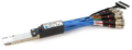 |
Description: QSFPDD-TPA2.92-MCB-R, (MCB, 2.92mm Fem, 400G) Part number: 640-0900-000 1 Model number: QSFPDD-TPA2.92-MCB-R 1 Quantity: 1 | 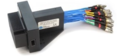 |
Description: QSFPDD-TPA2.4-HCB-RX-P (HCB, 8-RX-Pairs, 5-inch 2.4mm Fem, 112G / 800G) Test fixture plugs into QSFP-DD port Part number: 640-0899-131 1 Model number: QSFPDD-TPA2.4-HCB-RX-P 1 Quantity: 1 | 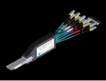 |
Description: QSFPDD-TPA1.85-MCB-R, (MCB, 1.85mm Fem, 800G) Test fixture receives QSFP-DD module Part number: 640-0900-200 1 Model number: QSFPDD-TPA1.85-MCB-R 1 Quantity: 1 | 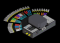 |
Description: OSFP-TPA1.85-HCB-P (HCB, 8-Channels, 5-inch 1.85mm Fem, 112G / 800G) Test fixture plugs into OSFP port Part number: 640-0935-200 1 Model number: OSFP-TPA1.85-HCB-P 1 Quantity: 1 | 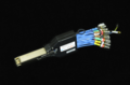 |
Description: OSFP-TPA1.85-MCB-R (MCB, 8-Channels, 5-inch 1.85mm Fem, 112G / 800G) Test fixture receives OSFP module Part number: 640-0937-200 1 Model number: OSFP-TPA1.85-MCB-R 1 Quantity: 1 |  |
Refer to Wilder Technologies https://www.wilder-tech.com/en for details regarding the various methods of signal break-out.
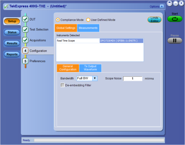
User-defined mode
In user-defined mode, users can configure Global parameters, test specific parameters, measurement repeat parameters, and notification parameters. This supports the characterization of measurements rather than developing custom lab setups, reducing the testing time and complexity.
De-embedding filters help in compensating for any loss that happens due to cables/accessories present between specification mentioned test point to analog channel of oscilloscope. SDLA can be used for creating de-embedding filter files.
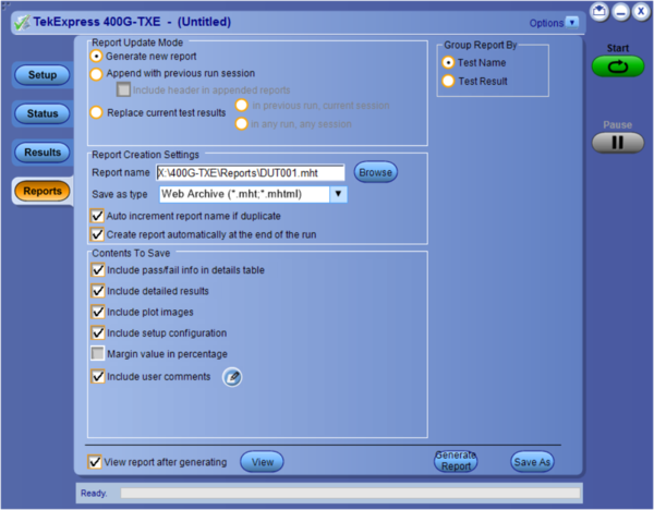
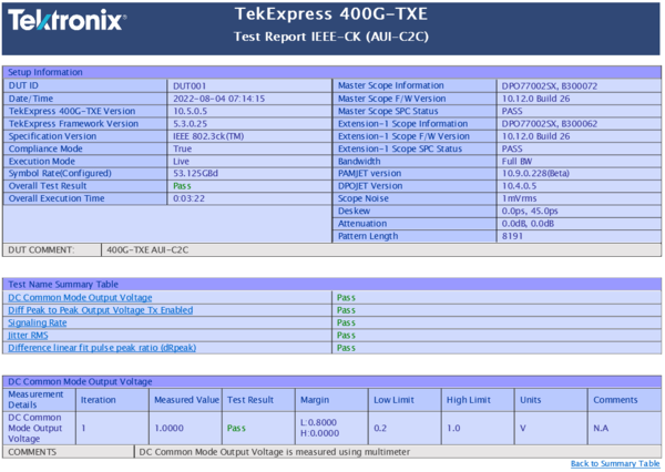
Reports and measurements results
Ordering information
Compliance testing to IEEE 802.3bs, 802.3cd, and 802.3ck Standards or OIF Standards for 400G at PAMJET, 26+ GBd /50Gb/s, and 53+ GBd /100Gb/s per lane requires a minimum of 2-stack SX oscilloscopes with Bandwidth ≥50 GHz (50 to approx 70Gb/s per lane) and 59 GHz (100Gb/s per lane and higher). When Tektronix oscilloscopes with lower bandwidth support the option, they might be used for troubleshooting.
Models
| Software description | Supported oscilloscopes | Ordering option |
|---|---|---|
| 802.3bs/802.3cd permanent node locked license ordered with a DPS70000SX or DPO70000SX or DPO73304DX or MSO73304DX Series Real-Time Oscilloscope | DPO73304SX, DPS73308SX, DPO75002SX, DPS75004SX, DPO75902SX, DPS75904SX, DPO77002SX, DPS77004SX, DPO73304DX, MSO73304DX | 400G-TXE |
| 802.3bs/802.3cd Floating License for use on any Real-Time Oscilloscope listed above | - | DPOFL-400G-TXE |
| 802.3bs/802.3cd Free 30-Day Trial License for use on any Real-Time Oscilloscope listed above | - | DPOFT-400G-TXE |
| 802.3ck permanent node locked license ordered with a DPS70000SX or DPO70000SX Series Real-Time Oscilloscope | DPO75902SX, DPS75904SX, DPO77002SX, DPS77004SX | 400GCK-TX |
| 802.3ck Floating License for use on any Real-Time Oscilloscope listed above | - | DPOFL-400GCK-TX |
| 802.3ck Free 30-Day Trial License for use on any Real-Time Oscilloscope listed above | - | DPOFT-400GCK-TX |
Prerequisites
The following oscilloscope software is required:
| Software details | Ordering option |
|---|---|
| PAMJET 3 Transmitter Analysis Software for electrical signals | PAMJET-E |
| PAMJET3 Measurement Analysis Software for 802.3ck (required for 802.3ck only) | PAM400GCK |
| DPOJET Jitter and Eye Analysis Tools - Advanced | DJA |
| DPOJET Jitter and Eye Analysis Tools - Noise (Optional) | DJAN |
| Serial Data Link Analysis toolkit (Optional) | SDLA64 |
Tektronix Asset Management System (AMS)
Optional software requires the purchase of a license before they are functional. Some software may require additional software licenses. Licenses are managed within the Tektronix Asset Management System (Tek AMS). The Tek AMS website address is https://www.tek.com/en/support/products/product-license. Product license management requires a login account.
Node Locked Licenses provide your own copy of the application on your instrument or personal computer and are permanently assigned to a specific Host ID or product model/serial number.
- Floating licenses can be moved between different Host IDs or product models.
Use the Tektronix Asset Management system to check in and check out floating licenses.
1 For a PMA in the same package as the PCS sublayer. In other cases, the signaling rate is derived from the signaling rate presented to the input lanes by the adjacent PMD, PMA, or FEC sublayers.
2 Refer to Wilder Technologies https://www.wilder-tech.com/en to get up-to-date part number and model number informations.
3 The PAMJET software package was formerly known as (fka) “PAM4".

Tektronix is ISO 14001:2015 and ISO 9001:2015 certified by DEKRA. Product(s) complies with IEEE Standard 488.1-1987, RS-232-C, and with Tektronix Standard Codes and Formats. 61W-61202-6

