Contactez-nous
Chat en direct avec un représentant Tek. Service disponible de 9 h à 17 h, CET jours ouvrables.
Téléphone
Appelez-nous au
Disponible de 9 h à 17 h CET jours ouvrables.
Télécharger
Télécharger des manuels, des fiches techniques, des logiciels, etc. :
Feedback
Programmable Pulse/Pattern Generator
PSPL1P601 and PSPL1P602 Datasheet
Les produits figurant sur cette fiche technique ne sont plus vendus par Tektronix.
Référez-vous à Tektronix Encore pour les équipements de test reconditionnés.
Consultez l'assistance et les informations de garantie pour ces produits.

PSPL1P601 and PSPL1P602 Datasheet
The PSPL1P601 and PSPL1P602 are effectively two instruments in one, a programmable pulse generator and a programmable pattern generator. This generator can operate in one of four modes, Pulse, Pattern, Burst, or External Width. There is also an option for built-in jitter insertion, an unprecedented capability for pulse/pattern generators at this price performance point.
Key performance specifications
- 15 MHz to 1.6 GHz operation
- 50 mV to 2.5 V programmable amplitude
- 150 ps rise time
- Programmable offset (-2.0 to +3.3 V window)
Key features
- Full Pulse and Pattern Generator capabilities
- 1 or 2 differential output channels
- NRZ, RZ, R1 data formats
- Programmable patterns
- User defined
- 16 Mbit per channel
- PRBS
- Built-in Jitter Insertion option
- Random
- Multi-UI sinusoidal
- Deterministic
- Built-in Spread Spectrum Clocking
- External trigger capability
- Adjustable trigger output
Applications
- Serial data generation
- Jitter tolerance testing
- General purpose pulse generator
Pulse and pattern generator modes
Fully programmable pulse generator with burst and external width modes. 
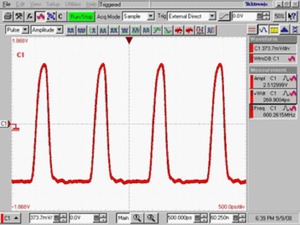
Pulse output at 800 MHz repetition rate and 2.5 V peak-to-peak amplitude
High-quality pattern generator with options for jitter insertion. 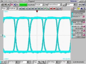
1.6 GHz, 27-1 PRBS, NRZ pattern, 2.5 V peak-to-peak amplitude
Typical performance
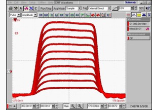
Programmable pulse amplitude (250 mV to 2.5 V) at 500 MHz rate and 900 ps width
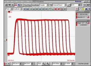
Programmable pulse width/duration at 200 MHz repetition rate and 2.0 V peak-to-peak amplitude
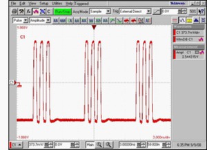
Pulse burst mode (3 pulses with a burst period of 8 pulses) at 800 MHz rate and 600 ps width
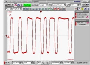
1.6 Gbps, 27-1 PRBS, NRZ pattern captured with pattern trigger (one per pattern)
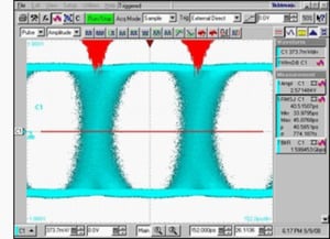
1.6 Gbps, 27-1 PRBS, NRZ pattern with built-in random delay modulation jitter insertion
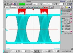
1.6 Gbps, 27-1 PRBS, NRZ pattern with built-in sine delay modulation jitter insertion
Specifications
All specifications are typical unless noted otherwise.
Output signal
The following notes apply to the output signal characteristics:
- The output characteristics apply to the Ch1 and Ch2 outputs.
- Ch1 and Ch2 are independent.
- True and complement outputs share the same settings. Differential values (true minus complement) are double those stated.
- The output is designed to drive into a 50 Ohm load terminated to a user-provided voltage. The termination voltage must be in the range specified. For the generator to display accurate levels, the user must enter the actual termination voltage.
- Each channel has independent delay and duration settings.
- Amplitude
-
- Range
- 50 mV to 2.5 V, within level window
- Resolution
- 3 digits (1 mV best case)
- Accuracy
- ±(50 mV + 1%), 50 Ω to 0 V termination
- Level window
-
- Range
- -2.0 V to +3.3 V
- Resolution
- 3 digits (1 mV best case)
- Offset
-
- Range
- -1.975 V to +3.275 V, within level window
- Resolution
- 3 digits (1 mV best case)
- Accuracy
- ±(50 mV +2%), 50 Ω to 0 V termination
- Termination voltage
-
- Range
- -2.0 V to +3.3 V
- Resolution
- 3 digits (1 mV best case)
- Baseline noise, RMS
- 1 mV
- Overshoot/Preshoot/RInging
- ±(5% + 50 mV), at 25 °C
- Signal rise/fall time
- 150 ps, 10 - 90 %
- Width/Duration
-
- Range
- 250 ps to (period-250 ps), May be set as duration or duty cycle
- Resolution
- 4 digits, 1 ps best case
- Accuracy
- ±(100 ps + 1%)
- Jitter RMS (trigger out to trailing edge)
- Delay
-
- Range
- 0 ps to period
- Resolution
- 4 digits, 1 ps best case
- Accuracy
- ±(50 ps + 1%), Relative to 0 delay setting
- Jitter RMS (trigger out to leading edge)
- Output impedance
- 50 Ω
Internal clock
The following notes apply to the internal clock characteristics:
- The clock source is shared between both channels.
- Some modes of operation (burst, pulse with external trigger, RZ/R1 patterns) are only specified to 800 MHz. However, over-programming is allowed for these modes, and some will work to frequencies higher than 800 MHz.
- Spread spectrum clocking and internal clock modulation sinusoidal jitter cannot be used at the same time.
- Frequency
-
- Range
- 15 MHz - 1.6 GHz, Can be set as frequency or period
- Resolution
- 1 Hz
- Accuracy
- ±100 ppm
- RMS Jitter (int ref, int clock, cycle-to-cycle)
- Pulse/Pattern clock source
- Internal Clock or “Clk In”
- Spread spectrum clocking
- 1 kHz - 100 kHz, 0% to 2%; Triangular wave frequency modulation of the clock at a specified frequency and % amplitude below nominal selected clock frequency
Pattern mode
- Pattern
-
- Types
- Data, PRBS
- PRBS length
- 2n - 1 with n = 5, 6…15, 23, 31
- Pattern length resolution
- 8 bits
- Memory depth
- 16 Mbit, per channel
- Data formats
-
- NRZ
- Yes, programmable crossing point
- RZ, R1
- Yes, programmable duration/duty cycle
- RZ, R1 max repetition rate
- 800 MHz, up to 1.6 GHz for NRZ data and 800 MHz for RZ, R1 data
- Crossing point adjustment
- For NRZ format only. Calibrated for 50% duty cycle data signals.
- Range
- 30 - 70%
- Resolution
- 1%
Burst mode
The following notes apply to the Burst mode characteristics
- Each channel has independent number of pulses and common burst period.
- See the Burst mode screen under Typical performance.
- Burst count
- 2 - 1,048,576 pulses, number of pulses in burst
- Burst period
-
- Range
- 8 - 1,048,576 clocks, number of clock cycles in a burst. Must be ≥ number of pulses.
- Resolution
- 8 clocks, clock cycles
- Maximum repetition rate in Burst mode
- 800 MHz
Jitter insertion
The following notes apply to the Jitter insertion specifications:
- The pulse generators are capable of generating jitter from two different mechanisms, modulation of the internal clock source or output channel delay modulation.
- Delay modulation sources can be either internal or external. External delay modulation is applied via an analog signal on the delay inputs (separate for each channel).
- Modulation of the internal clock is applied to both channels of a two-channel instrument.
- Delay modulation jitter may be applied to each channel independently with the ability to apply different jitter functions to each channel.
- Internal clock and delay modulation jitter can be applied in any combination. The combined peak-to-peak amplitude of delay modulation jitter (deterministic waveforms, random, and external) is limited to 0.5 UI.
- The trigger output is also subject to the internal clock modulation jitter but not delay modulation jitter.
- The bandwidth of the delay modulation jitter depends on the clock frequency. Below 300 MHz clock frequency, the delay modulation jitter insertion bandwidth will be reduced. Jitter insertion signal frequencies approaching ½ of the clock frequency or higher are not recommended and can result in unexpected behavior (due to in-band mix products / undersampling).
- Spread spectrum clocking and internal clock modulation sinusoidal jitter cannot be used at the same time.
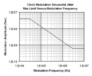
- The following figure shows a plot of the limit points (linearly interpolated on a log-log scale between stated frequency points) for internal clock modulation sinusoidal jitter:

- Internal clock modulation sinusoidal jitter (peak-to-peak)
- Jitter amplitude range is from 0 ns to the values at the specified frequencies. Between the frequencies, the limit points are interpolated linearly on log-log scale plot. Please refer to the Clock Modulation plot.
- 10 kHz & 30 kHz
- 40 ns
- 3 MHz & 10 MHz
- 0.6 ns
- Delay Modulation Jitter
- See the bandwidth note above.
- Deterministic waveforms
-
Square (peak-to-peak), 1 Hz to 20 MHz: 0 to 0.4 UI
Triangle (peak-to-peak), 1 Hz to 4 MHz: 0 to 0.5 UI
Sine (peak-to-peak), 1 Hz to 20 MHz: 0 to 0.5 UI (See Sine Delay Modulation Jitter Insertion figure above for an example.)
- Random jitter Gausian noise (RMS)
- 80 MHz BW: 0 to 0.08 UI (See Random Delay Modulation Jitter Insertion figure above for an example.)
- External input (peak-to-peak)
- 80 MHz BW: 0 to 0.5 UI (±1 V maximum useable input with 2 V peak-to-peak input corresponding to peak-to-peak jitter of 0.5 UI. See the bandwidth note above.)
Trigger types
- When in Pulse mode
-
- Continuous
- One pulse per period of the internal clock or Clk In
- Ext In, Edge
- One pulse per valid edge on the Ext In input. The latency between the Ext In signal and the output signal is repeatable (deterministic) and is adjustable with the delay control. The Ext In signal can vary from single shot to 800 MHz. Clk In is not used.
- Ext In, Level
- The active Ext In level enables continuous pulses. The Pulse period is set by internal clock or Clk In. The clock frequency is limited to 800 MHz. The latency between trigger source and signal output is not fixed or deterministic.
- Remote/Manual
- A trigger command from the remote interface or front panel generates a single pulse. Clk In is not used.
- When in Burst or Pattern mode
-
- Continuous
- Trigger circuitry is always armed. Clock can be internal or Clk In. Bursts or Patterns are continuously generated.
- Ext In, Edge
- The active transition on Ext In generates one burst or pattern. The Burst or Pattern pulse period is set by internal clock or Clk In. There is no fixed latency between trigger source and signal output.
- Ext In, Level
- The active Ext In level enables continuous bursts or patterns. On an inactive input level, a burst or pattern in progress will finish before halting. The Burst or Pattern pulse period is set by internal clock or Clk In. The latency between trigger source and signal output is not fixed or determinant.
- Remote/Manual
- A trigger command from the remote interface or front panel generates a single burst or pattern. The Burst or Pattern pulse period is set by internal clock or Clk In.
- When in External width mode
-
- No triggering
- Outputs follow the Ext In signal. The trigger output is not active.
Inputs
- Front panel inputs
- SMA jacks, 50 Ω impedance
- Rear panel input
- BNC jack, 50 Ω impedance
- Clk In
- Accepts external clock to set the pulse period. AC coupled signal with selectable AC or DC coupling of the termination.
- Termination voltage
- -2 V to +3 V (active only for DC coupled termination)
- Input absolute limits
- 2.6 V maximum AC peak-to-peak, -2 V to +3 V DC
- Input frequency
- 15 MHz - 800 MHz except for NRZ Pattern, then 15 MHz - 1.6 GHz
- Ext In
-
Accepts external signal to start or gate the burst/pattern or the trigger pulse, DC coupled.
- Termination voltage
- -2 V to +3 V
- Input threshold
- -2 V to +3 V
- Input absolute limits
- -3 V to +4 V
- Input frequency
- DC to 800 MHz
- Delay In (1 and 2)
-
Accepts external signal for jitter insertion on channels 1 & 2. 50 Ω, DC coupled.
- Voltage range
- -1 V to +1 V
- Input absolute limits
- ±5 V
- REF IN (rear panel)
- Reference oscillator input accepts external 10 MHz signal for timebase reference.
- Termination voltage
- AC Coupled, 50 Ω
- Input amplitude
- 0 dBm
- Input absolute limits
- 4 V maximum AC peak-to-peak, ±10 V DC
Outputs
- Front panel outputs
- SMA jacks, 50 Ω impedance
- Rear panel output
- BNC jack, 50 Ω impedance
- OUT 1 and /OUT 1
- Output 1 is the Channel 1 signal output; /Output 1 is the Channel 1 complement signal output.
- OUT 2 and /OUT 2
- Output 2 is the Channel 2 signal output; /Output 2 is the Channel 2 complement signal output.
- Trig Out
- Generates trigger pulse corresponding to each output pulse or start of burst or pattern, DC coupled.
- Adjustable amplitude range
- 50 mV to 2.5 V
- Adjustable offset range
- -2 V to +3.3 V window
Output modes
- Pulse mode
- Pulse mode delivers a single pulse per trigger event. The pulse timing is programmable in repetition rate, duration, and delay.
- Pattern mode
- Pattern mode delivers a defined pattern per trigger event. The pattern may be presented in either NRZ, RZ, or R1 formats. In NRZ mode the crossing point is programmable. In RZ and R1 mode the duration of the pattern pulse is programmable.
- Burst mode
- Burst mode delivers a ‘burst’ of n pulses per trigger event.
- External width mode
- External width mode delivers pulse levels that follow the edges of the “Ext In” input. A rising edge causes the output to go high, while a falling edge causes the output to go low.
General characteristics
- REF OUT (rear panel)
- Reference oscillator output, generates 10 MHz signal phase locked to instrument timebase.
- Signal amplitude (peak-to-peak)
- 1.4 V
- Ref Osc output impedance
- AC coupled, 50 Ω
- Interfaces
- The PSPL1P601 and PSPL1P602 generators can be controlled by either the front panel GUI interface, a GPIB interface, or a USB interface. IEEE 488.2, SCPI compliant.
- Mechanical dimensions
- Size: 439 mm (17.3 in) wide x 87 mm (3.4 in) high x 421 mm (16.6 in) deep
- Temperature
- Operating Ambient Temperature: 0 to 50 °C
Specifications apply from 0 to 50 °C unless otherwise noted.
All ventilation openings must allow unobstructed flow of ambient air.
- Warranty
- One year
Ordering information
Models
- PSPL1P601
- 1.6 GHz PULSE/PAT GEN, 1 CH
- PSPL1P602
- 1.6 GHz PULSE/PAT GEN, 2 CH
Options
- PSPL1P601 JIT
- 1.6 GHz PULSE/PAT GEN, 1 CH, JITTER
- PSPL1P602 JIT
- 1.6 GHz PULSE/PAT GEN, 2 CH, JITTER


