Contactez-nous
Chat en direct avec un représentant Tek. Service disponible de 9 h à 17 h, CET jours ouvrables.
Téléphone
Appelez-nous au
Disponible de 9 h à 17 h CET jours ouvrables.
Télécharger
Télécharger des manuels, des fiches techniques, des logiciels, etc. :
Feedback
PSPL5933 Flat Group Delay Low-Pass Filter Datasheet
PSPL5933 Datasheet
Les produits figurant sur cette fiche technique ne sont plus vendus par Tektronix.
Référez-vous à Tektronix Encore pour les équipements de test reconditionnés.
Consultez l'assistance et les informations de garantie pour ces produits.

PSPL5933 Datasheet
The PSPL5933 Flat Group Delay Low-Pass Filter is designed for OEM use in high-speed digital networks and telecom systems. The devices use a proprietary, absorptive filter design that has attenuation and time domain characteristics similar to those of the 4th order Bessel-Thomson filter. Traditional Bessel-Thomson designs filter by reflecting stop-band frequency signals and thus can cause increased bit error rates and eye diagram closure due to multiple reflections. By contrast, the PSPL5933 filters by absorption. It has excellent impedance matches and very good return losses, both within and above the filter pass band. The Flat Group Delay style filter exhibits quasi-Gaussian insertion loss characteristics, with superior time domain performance.
Typical performance, option 7P46GHZ
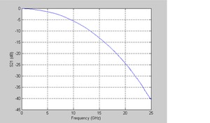
The following figure shows the insertion loss from 0 to 25 GHz.

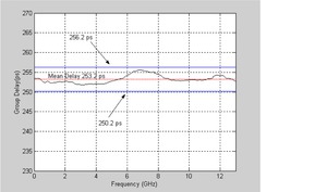
The following figure shows the group delay from 0.1 to 13 GHz.
The following figure shows the input return loss from 0 to 25 GHz.
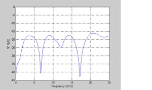
The following figure shows the output return loss from 0 to 25 GHz.
The following figure shows the TDT response to 15 ps step with the time base at 50 ps/div.
Typical performance, option 8GHZ
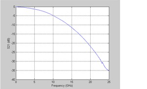
The following figure shows the insertion loss from 0 to 25 GHz.
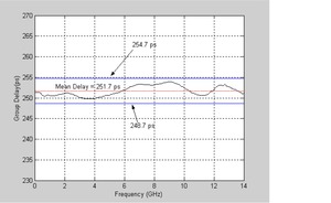
The following figure shows the group delay from 0.1 to 14 GHz.
The following figure shows the Input return loss from 0 to 25 GHz.
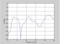
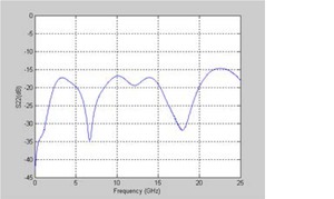
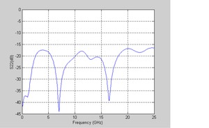
The following figure shows the output return loss from 0 to 25 GHz.
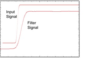
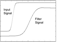
The following figure shows the TDT response to 15 ps step with the time base at 20 ps/div.
Specifications
All specifications apply to all models unless noted otherwise.
| Parameter 1 | PSPL5933 opt. 7P46GHZ | PSPL5933 opt. 8GHZ |
|---|---|---|
| Impedance | 50 Ω | |
| Bandwidth (-3 dB) | 7.46 GHz | 8 GHz |
| Bandwidth Tolerance (at 23 °C) | ± 3% maximum | |
| Bandwidth Thermal Drift | -2.1 MHz / °C typical, -3.1 MHz / °C maximum | |
| Rise time, 10% – 90% | 47 ps | 46 ps |
| RF Power | 29 dBm maximum | |
| Operating Temperature | -10 to +70 °C, maximum power | |
| Return Loss (S11 and S22) | >12 dB | |
| Group Delay | 253 ps | |
| Group Delay Flatness | ±3 ps | |
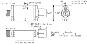
| Connectors | SMA jack (f) & plug (m) | |
| Warranty | One year | |
1 All parameters listed are typical unless max/min guaranteed limits are provided.
Ordering information
Models
- PSPL5933
- Flat Group Delay Low-Pass Filter
Options
- PSPL5933 7P46GHZ
- 7.46 GHz 3 dB frequency
- PSPL5933 8GHz
- 8 GHz 3 dB frequency


