TriggerFlow building blocks allow creating triggering models that range from very simple to highly complex.
Contactez-nous
Chat en direct avec un représentant Tek. Service disponible de 9 h à 17 h, CET jours ouvrables.
Téléphone
Appelez-nous au
Disponible de 9 h à 17 h CET jours ouvrables.
Télécharger
Télécharger des manuels, des fiches techniques, des logiciels, etc. :
Feedback
2460 Source Measure Unit
2460 SMU Instrument Datasheet
Plus d’informations
- SMU série graphique 2400
- Assistance produit
- Découvrez d'autres modèles Unités de source et de mesure (SMU) Keithley
Lire en ligne :
2460 SMU Instrument Datasheet
The 2460 High Current SourceMeter® Source Measure Unit (SMU) Instrument brings advanced Touch, Test, Invent® technology right to your fingertips. It combines an innovative graphical user interface (GUI) with capacitive touchscreen technology to make testing intuitive and minimize the learning curve to help engineers and scientists learn faster, work smarter, and invent easier. With its 7 A DC and pulse current capability, the 2460 is optimized for characterizing and testing high power materials, devices, and modules such as silicon carbide (SiC), gallium nitride (GaN), DC-DC converters, power MOSFETs, solar cells and panels, LEDs and lighting systems, electrochemical cells and batteries, and much more. These new capabilities, combined with Keithley’s decades of expertise in developing high precision, high accuracy SMU instruments, will make the 2460 a “go-to instrument” for high current applications in the lab and in the rack for years to come.
Key Features
- One tightly coupled instrument that combines capabilities from analyzers, curve tracers, and I-V systems at a fraction of their cost
- Wide coverage up to 105 V, 7 A DC/7 A pulse, 100 W max.
- Five-inch, high-resolution capacitive touchscreen GUI
- 0.012% basic measure accuracy with 6½-digit resolution
- Source and sink (4-quadrant) operation
- Four “Quickset” modes for fast setup and measurements
- Context-sensitive help function
- Front panel input banana jacks; rear panel input mass termination screw connections
- 2460 SCPI and TSP® scripting programming modes
- Front-panel USB 2.0 memory I/O port for transferring data, test scripts, or test configurations

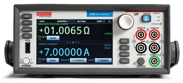
2460 main home screen.
Learn Faster, Work Smarter, Invent Easier
The 2460 features a five-inch, full-color, high-resolution touchscreen that supports intuitive operation, helps operators become familiar with the instrument quickly, and optimizes overall speed and productivity. A simple icon-based menu structure reduces the number of steps required to configure a test by as much as 50 percent and eliminates the cumbersome multi-layer menu structures typically used on soft-key instruments. Built-in, context-sensitive help supports intuitive operation and minimizes the need to review a separate manual. These capabilities, combined with the 2460’s high versatility, simplify its operation in both basic and advanced measurement applications, regardless of the user’s previous experience in working with SMU instruments.


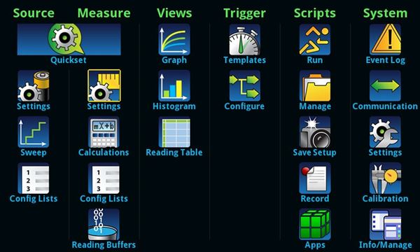
2460 icon-based menu.
All-in-One SMU Instrument
The 2460, built on the fourth generation of the award-winning SourceMeter SMU platform, leverages the proven capabilities of previously introduced high current SMU instruments from Keithley, including the 2420, 2425, and 2440. It offers a highly flexible, four-quadrant voltage and current source/load coupled with precision voltage and current measurements. This all-in-one instrument gives you the capabilities of a:
- Precision power supply with V and I readback
- True current source
- Digital multimeter (DCV, DCI, ohms, and power with 6½-digit resolution)
- Precision electronic load
- Trigger controller

DC or Pulsed.
Comparison Table: 2420, 2425, and 2440 with 2460
| 2420/2425/2440 | 2460 |
| Maximum Voltage: 60 V/100 V/40 V | Maximum Voltage: 100 V |
| Maximum Current: 3 A/3 A/5 A | Maximum Current: 7 A |
| DC Power: 60 W/100 W/50 W | DC Power: 100 W |
| Wideband Noise: 10 mVrms typ. | Wideband Noise: 2mVrms typ. |
| Sweep Types: Linear, Log, Custom, Source-Memory | Sweep Types: Linear, Log, Dual Linear, Dual Log, Custom |
| 5000 Point Reading Buffer | >250,000 Point Reading Buffer |
| >2000 Readings/second | >3000 Readings/second |
| SCPI Programming | SCPI Programming + TSP Scripting |
| GPIB, RS-232 | GPIB,USB, Ethernet(LXI) |
| Front/Rear Banana Jacks | Front: Banana Jacks. Rear: Mass Screw Terminal Connection |
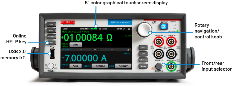
2460 front panel with high-resolution, capacitive touchscreen.
Ease of Use Beyond the Touchscreen
In addition to its advanced touchscreen, the 2460’s front panel offers a variety of features that enhance its speed, user-friendliness, and learnability, including a USB 2.0 memory I/O port, a HELP key, a rotary navigation/control knob, a front/rear input selector button, and banana jacks for basic bench applications. The USB 2.0 memory port simplifies storing test results and instrument configurations, uploading test scripts into the instrument, and installing system upgrades. All front-panel buttons are backlit to enhance visibility in low-light environments.
Four “Quickset” modes simplify instrument setup. With one touch, the instrument can be quickly configured for various operating modes without the need to configure the instrument indirectly for this operation.

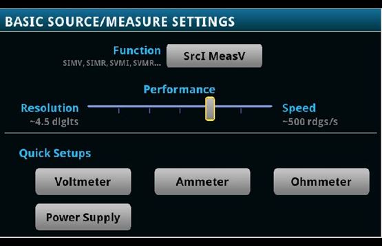
One-touch Quickset modes speed measurement setups and minimize the time to measurements.
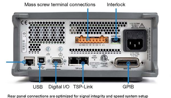
Comprehensive Built-in Connectivity
Rear panel access to rear-input mass termination connector, remote control interfaces (GPIB, USB 2.0, and LXI/Ethernet), D-sub 9-pin digital I/O port (for internal/ external trigger signals and handler control), instrument interlock control, and TSP-Link® jacks make it simple to configure multiple instrument test solutions and eliminate the need to invest in additional adapter accessories.

Convert Raw Data to Information
A full graphical plotting window converts raw data and displays it immediately as useful information, such as semiconductor I-V curves and voltammograms. Using the 2460’s Sheet view, test data can also be displayed in tabular form. The instrument supports exporting data to a spreadsheet for further analysis, dramatically improving productivity for research, benchtop testing, device qualification, and debugging.
TriggerFlow® Building Blocks for Instrument Control and Execution
The 2460 incorporates Keithley’s TriggerFlow triggering system, which provides user control over instrument execution. TriggerFlow diagrams are created in much the same way that flow charts are developed, using four fundamental building block types:
- Wait – Waits for an event to occur before the flow continues
- Branch – Branches when a condition has been satisfied
- Action – Initiates an action in the instrument, for example, measure, source, delay, set digital I/O, etc.
- Notify – Notifies other equipment that an event has occurred
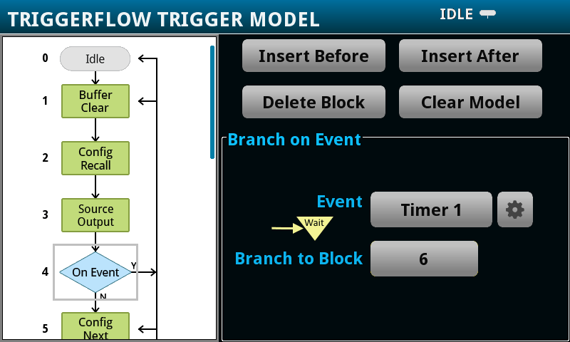
A TriggerFlow model using a combination of these building blocks can be created from the front panel or by sending remote commands. With the TriggerFlow system, users can build triggering models from very simple to complex with up to 63 block levels. The 2460 also includes basic triggering functions, including immediate, timer, and manual triggering.


Unmatched System Integration and Programming Flexibility
When a 2460 is configured into a multi-channel I-V test system, its embedded Test Script Processor (TSP) allows it to run test scripts, so users can create powerful measurement applications with significantly reduced development times. TSP technology also offers channel expansion without a mainframe. Keithley’s TSP-Link channel expansion bus, which uses a 100 Base T Ethernet cable, can connect multiple 2460s and other TSP instruments such as Keithley’s 2450 SourceMeter SMU Instruments, Series 2600B System SourceMeter SMU instruments, and Series 3700A Switch/Multimeter systems in a master-subordinate configuration that operates as one integrated system. The TSP-Link expansion bus supports up to 32 units per GPIB or IP address, making it easy to scale a system to fit an application’s particular requirements. The 2460 also includes a SCPI programming mode that takes advantage of all of the instrument’s capabilities.
Parallel Test Capability
The TSP technology in the 2460 supports testing multiple devices in parallel to meet the needs of device research, advanced semiconductor lab applications, and even high throughput production test. This parallel testing capability allows each instrument in the system to run its own complete test sequence, creating a fully multi-threaded test environment. The number of tests that can be run in parallel on a 2460 can be as high as the number of instruments in the system.
Instrument Control Start-up Software
KickStart instrument control/start-up software enables users to start making measurements in minutes without programming. In most cases, users merely need to make some quick measurements, graph the data, and store the data to disk for later analysis in software environments such as Microsoft Excel. KickStart offers:
- Configure and control up to four SMU instruments for DC or Pulsed I-V test in either the same app, same project, or a combination of the two.
- Create tests by mixing any of these SMU instruments: 2400 Graphical Series, 2400 Standard Series (DC only), 2600B Series, 2651A, 2657A, and 6430 SourceMeter SMU (DC only) instruments.
- Differentiate SMU instrument channels and their measurement data using labels that are relevant to your device or module.
- Native X-Y graphing, panning, and zooming; screenshot capturing of graphs.
- Spreadsheet/tabular viewing of data; export data for further analysis.
- Annotating of tests; save test setups.
- GPIB, USB 2.0, Ethernet compliance.


KickStart start-up software lets users be ready to take measurements in minutes.
Optional Apps Tailored for your Characterization Needs
The 2460 is an excellent tool to define nearly any DC test you choose for characterizing materials, electronic devices and modules. For more specific needs, Keithley offers on-instrument software apps that alter the 2460’s behavior, fitting your instrument to your needs. These apps can be installed directly to your 2460 by connecting to Keithley’s KickStart instrument control software and opening the relevant app in KickStart.
I-V Tracer App
Curve tracing analysis is a critical task for many users in the semiconductor development supply chain. Engineers and technicians both hold the traditional curve tracer as the simplest, fastest method for generating characteristic I-V curves on a device. They are heavily used by engineers in failure analysis and incoming inspection to qualify parts, identify counterfeit devices, and to quickly identify the location of a failure on damaged devices. SMUs have typically been limited to predefined sweeps with longer set up times than curve tracers — until I-V Tracer.
Simplified Programming with Ready-to-Use Instrument Drivers
For those who prefer to create their own customized application software, native National Instruments LabVIEW® drivers and IVI-C and IVI-COM drivers are available at tek.com.
Specifications
Voltage Specifications1, 2
|
Source |
Measure 3 |
||||||
|
Range |
Max. Current |
Resolution |
Accuracy (23° ± 5°C)1 Year±(% setting + volts) |
Noise (RMS) (<10 Hz) |
Resolution |
Input Resistance |
Accuracy (23° ± 5°C)1 Year±(% rdg. + volts) |
|
200.0000 mV |
7.35 A |
5 μV |
0.015% + 200 µV |
1 µV |
100 nV |
>10 GΩ |
0.012% + 200 µV |
|
2.000000 V |
7.35 A |
50 µV |
0.015% + 300 µV |
10 µV |
1 µV |
>10 GΩ |
0.012% + 300 µV |
|
7.000000 V |
7.35 A |
250 µV |
0.015% + 2.4 mV |
100 µV |
1 µV |
>10 GΩ |
0.015% + 1 mV |
|
10.00000 V |
5.25 A |
500 µV |
0.015% + 2.4 mV |
100 µV |
10 µV |
>10 GΩ |
0.015% + 1 mV |
|
20.00000 V |
4.20 A |
500 µV |
0.015% + 2.4 mV |
100 µV |
10 µV |
>10 GΩ |
0.015% + 1 mV |
|
100.0000 V |
1.05 A |
2.5 mV |
0.015% + 15 mV |
1 mV |
100 µV |
>10 GΩ |
0.015% + 5 mV |
Current Specifications 1, 2, 5
|
Source |
Measure3 |
||||||
|
Range |
Max. Voltage |
Resolution |
Accuracy (23° ±5°C) 4 1 Year±(% setting + amps) |
Noise (RMS) (<10 Hz) |
Resolution 4 |
Voltage Burden 6 |
Accuracy (23° ±5°C) 1 Year±(% rdg. + amps) |
|
1.000000 μA |
105 V |
50 pA |
0.025% + 1 nA |
40 pA |
10 pA |
<100 µV |
0.025% + 700 pA |
|
10.00000 μA |
105 V |
500 pA |
0.025% + 1.5 nA |
40 pA |
10 pA |
<100 µV |
0.025% + 1 nA |
|
100.0000 μA |
105 V |
5 nA |
0.020% + 15 nA |
100 pA |
100 pA |
<100 µV |
0.020% + 10 nA |
|
1.000000 mA |
105 V |
50 nA |
0.020% + 150 nA |
1 nA |
1 nA |
<100 µV |
0.020% + 100 nA |
|
10.00000 mA |
105 V |
500 nA |
0.020% + 1.5 μA |
10 nA |
10 nA |
<100 µV |
0.020% + 1 μA |
|
100.0000 mA |
105 V |
5 μA |
0.020% + 15 μA |
100 nA |
100 nA |
<100 µV |
0.020% + 10 μA |
|
1.000000 A |
105 V |
50 μA |
0.050% + 750 μA |
5 μA |
1 μA |
<100 µV |
0.050% + 500 μA |
|
4.000000 A |
21 V |
250 μA |
0.100% + 3 mA |
25 μA |
1 μA |
<100 µV |
0.100% + 2.5 mA |
|
5.000000 A |
10.5 V |
250 μA |
0.100% + 3 mA |
25 μA |
1 μA |
<100 µV |
0.100% + 2.5 mA |
|
7.000000 A |
7.35 V |
500 μA |
0.150% + 6 mA |
125 μA |
1 μA |
<100 µV |
0.150% + 5 mA |
Temperature Coefficient
(0°–18°C and 28°–50°C) — ±(0.10 × accuracy specification)/°C.
Notes
- Speed = 1 PLC.
- All specifications are guaranteed with output ON.
- Accuracies apply to 2- and 4-wire mode when properly zeroed.
- 6.5-digit measure resolution.
- Accuracy specifications guaranteed when using 2460-KIT screw terminal accessory.
- Four-wire mode.
Resistance Measurement Accuracy (Local or Remote Sense) 1, 2, 3
|
Range |
Default Resolution 4 |
Default Test Current |
Normal Accuracy (23°C ±5°C) 1 Year, ±(% rdg. + ohms) |
Enhanced Accuracy 5 (23°C ±5°C) 1 Year, ±(% rdg. + ohms) |
|
<2.000000 Ω6 |
1 μΩ |
User defined |
Source IACC + Meas. VACC |
Meas. IACC + Meas. VACC |
|
20.00000 Ω |
10 μΩ |
100 mA |
0.05% + 0.003 Ω |
0.04% + 0.001 Ω |
|
200.0000 Ω |
100 μΩ |
10 mA |
0.05% + 0.03 Ω |
0.04% + 0.01 Ω |
|
2.000000 kΩ |
1 mΩ |
1 mA |
0.05% + 0.3 Ω |
0.04% + 0.1 Ω |
|
20.00000 kΩ |
10 mΩ |
100 μA |
0.05% + 3 Ω |
0.04% + 1 Ω |
|
200.0000 kΩ |
100 mΩ |
10 μA |
0.05% + 30 Ω |
0.05% + 10 Ω |
|
2.000000 MΩ |
1 Ω |
10 μA |
0.06% + 100 Ω |
0.06% + 50 Ω |
|
20.00000 MΩ |
10 Ω |
1 μA |
0.14% + 1000 Ω |
0.12% + 500 Ω |
|
>20.0000 MΩ6 |
— |
User defined |
Source IACC + Meas. VACC |
Meas. IACC + Meas. VACC |
Temperature Coefficient
(0°–18°C and 28°–50°C) — ±(0.10 × accuracy specification)/°C.
Source Current,
Measure Resistance Mode — Total uncertainty = Isource accuracy + Vmeasure accuracy (4-wire remote sense).
Source Voltage,
Measure Resistance Mode — Total uncertainty = Vsource accuracy + Imeasure accuracy (4-wire remote sense).
Guard Output Impedance — 0.5 Ω (DC) in ohms mode.
Notes
- Speed = 1 PLC.
- All specifications are guaranteed with output ON.
- Accuracies apply to 2- and 4-wire mode when properly zeroed.
- 6.5-digit measure resolution.
- Source readback enabled. Offset compensation ON.
- Source current, measure resistance or source voltage, measure resistance only.
Supplemental Characteristics
Max. Output Power — 100 W, four-quadrant source or sink operation.
Source Limits — Vsource: ±7.35 V (≤7 A range), ±10.5 V (≤5 A range), ±21 V (≤4 A range), ±105 V (≤1 A range). Isource: ±7.35 A (≤7 V range), ±5.25 A (≤10 V range), ±4.2 A (≤20 V range), ±1.05 mA (≤100 V range).
Overrange — 105% of range, source and measure.
Regulation — Voltage: Line: 0.01% of range. Load: 0.01% of range + 100 µV. Current: Line: 0.01% of range. Load: 0.01% of range + 100 pA.
Source Limits — Voltage Source Current Limit: Bipolar current limit set with single value. Min. 10% of range. Current Source Voltage Limit: Bipolar voltage limit set with single value. Min. 10% of range.
V-Limit / I-Limit Accuracy — Add 0.3% of setting and ±0.02% of reading to base specification.
Overshoot — Voltage Source: <0.1% typical (full scale step, resistive load, 20 V range, 10 mA I-Limit. Current Source: <0.1% typical (1 mA step, RLoad = 10 kΩ, 20 V range).
Range Change OvershootOvershoot into a fully resistive 100 kΩ load, 10 Hz to 20 MHz BW, adjacent ranges: <250 mV typical.
Output Settling Time — Time required to reach 0.1% of final value after command is processed and output slew, 20 V range, 100 mA I-Limit: <200 µs typical.
Maximum Slew Rate — 1 V per µs, 100 V range, 100 mA limit into a 20 kΩ load (typical). 0.6 V per µs, 20 V range, 100 mA limit into a 20 kΩ load (typical).
Over Voltage Protection — User selectable values, 5% ±0.5 V tolerance. Factory default = none.
Voltage Source Noise — 10 Hz–20 MHz (RMS): <4.5 mV typical into a resistive load.
Common Mode Voltage — 250 V DC.
Common Mode Isolation — >1G Ω, <1000 pF.
Noise Rejection (typical)
|
NPLC |
NMRR |
CMRR |
|
0.01 |
— |
60 dB |
|
0.1 |
— |
60 dB |
|
1 |
60 dB |
100 dB |
Load Impedance — Normal Mode: 20 nF typical. High Capacitance Mode: Stable into 50 μF typical. High-C mode valid for ≥100 µA ranges.
Max. Voltage Drop Between
Force and Sense Terminals — 5 V.
Max. Sense Lead Resistance — 1 MΩ for rated accuracy.
Sense Input Impedance — >10 GΩ.
Guard Offset Voltage — <300 µV, typical
System Measurement Speeds 1
Reading Rates (readings/second) typical for 60 Hz (50 Hz), script (TSP®) programmed
|
NPLC |
Trigger Origin |
Measure to Memory |
Measure to GPIB/USB/LAN |
Source-Measure to Memory |
Source-Measure to GPIB/USB/LAN |
|
0.01 |
Internal |
3050 (2800) |
2800 (2500) |
1700 (1600) |
1650 (1550) |
|
0.01 |
External |
2300 (2100) |
2150 (2000) |
1650 (1550) |
1600 (1450) |
|
0.1 |
Internal |
540 (460) |
530 (450) |
470 (410) |
470 (400) |
|
0.1 |
External |
500 (420) |
500 (420) |
460 (390) |
450 (350) |
|
1.00 |
Internal |
59 (49) |
59 (49) |
58 (48) |
58 (48) |
|
1.00 |
External |
58 (48) |
58 (48) |
57 (48) |
57 (46) |
Reading Rates (readings/second) typical for 60 Hz (50 Hz), SCPI programmed
|
NPLC |
Trigger Origin |
Measure to Memory |
Measure to GPIB/USB/LAN |
Source-Measure to Memory |
Source-Measure to GPIB/USB/LAN |
|
0.01 |
Internal |
3000 (2800) |
3000 (2790) |
1700 (1600) |
1550 (1500) |
|
0.01 |
External |
2330 (2150) |
2330 (2150) |
1650 (1550) |
1500 (1450) |
|
0.1 |
Internal |
540 (460) |
540 (460) |
470 (410) |
460 (400) |
|
0.1 |
External |
510 (430) |
510 (430) |
470 (400) |
460 (390) |
|
1.00 |
Internal |
59 (49) |
59 (49) |
58 (48) |
58 (48) |
|
1.00 |
External |
58 (49) |
58 (49) |
58 (48) |
58 (48) |
Notes
- Reading rates applicable for voltage or current measurements, autozero off, autorange off, filter off, binary reading format, and source readback off.
General Characteristics (default mode unless specified)
Factory Default
Standard Power-Up — SCPI Mode.
Source Output Modes — Fixed DC Level, Memory/Configuration List (mixed function), Sweep (linear and logarithmic), Sweep (dual linear and dual logarithmic.
Memory Buffer — >250,000 readings. Includes selected measured values and timestamp.
Real-Time Clock — Lithium battery backup (3 yr. + battery life).
Remote Interfaces
GPIB — IEEE-488.1 compliant. Supports IEEE-488.2 common commands and status model topology.
USB Device (rear panel, type B) — 2.0 Full Speed USBTMC.
USB Host (front panel, type A) — USB 2.0, support for flash drives, FAT32.
Ethernet: RJ-45 (10/100BT)
Digital I/O Interface
Lines — 6 Input/Output user defined for digital I/O or triggering.
Connector — 9-pin female D.
Input Signal Levels — 0.7 V (maximum logic low), 3.7 V (minimum logic high).
Input Voltage Limits — –0.25 V (absolute minimum), +5.25 V (absolute maximum).
Maximum Source Current — +2.0 mA @ >2.7 V (per pin).
Maximum Sink Current — –50 mA @ 0.7 V (per pin, solid-state fuse protected).
5 V Power Supply Pin — Limited to 500 mA @ >4 V (solid-state fuse protected).
Handler — User definable Start of Test, End of Test, 4 category bits.
Programmability — SCPI or TSP command sets.
TSP Mode — Embedded Test Script Processor (TSP) accessible from any host interface.
IP Configuration — Static or DHCP.
Expansion Interface — The TSP-Link expansion interface allows TSP enabled instruments to trigger and communicate with each other.
LXI Compliance — 1.5 LXI Device Specification 2016.
Display — 5 inch capacitive touch, color TFT WVGA (800×480) with LED backlight.
Input Signal Connections — Front: Banana. Rear: Mass termination screw terminal.
Interlock — Active High Input.
Cooling — Forced air, variable speed.
Over Temperature Protection — Internally sensed temperature overload puts unit in standby mode.
Power Supply — 100 V to 240 V RMS, 50–60 Hz (automatically detected at power up).
VA Rating — 350 volt-amps maximum.
Altitude — Maximum 2000 meters above sea level.
EMC — Conforms to European Union EMC Directive.
Safety — Compliance with CE and NRTL listed to UL61010-1 and UL61010-2-30. Conforms with European Union Low Voltage Directive.
Vibration — MIL-PRF-28800F Class 3 Random.
Warm-Up — 1 hour to rated accuracies.
Dimensions — With bumpers and handle: 106 mm high × 255 mm wide × 425 mm deep (4.18 in × 10.05 in × 16.75 in). Without bumpers and handle: 88 mm high × 213 mm wide × 403 mm deep (3.46 in × 8.39 in × 15.87 in.)
Weight — With bumpers and handle: 4.75 kg (10.5 lbs.).Without bumpers and handle: 4.35 kg (9.6 lbs.).
Environment — For indoor, non-residential use only. Operating: 0° to 50°C, 70% relative humidity up to 35°C. Derate 3% relative humidity/°C, 35° to 50°C. Storage: –25°C to 65°C.
Accessories Supplied — Test Leads, Mating Mass Termination Screw Connector, USB Cable, Ethernet/TSP Cable, Interlock Adapter, Power Cord, Quick Start Guide.
Ordering Information
2460 100 V, 7 A, 100 W SourceMeter Instrument
Supplied Accessories
2460-KIT — Rear Panel Mating Mass Termination Screw Connector
CS-1616-3 — Safety Interlock Mating Connector
17469460X — TSP-Link/Ethernet Cable
CA-432A — USB 2.0 Type A Male to Type B Male Cable
012173001 — Safety Clip On Test Lead Set
2460 Quick Start Guide
TSP Toolkit Software (available at tek.com)
LabVIEW and IVI Drivers (available at tek.com)
Available Accessories
Test Leads and Probes
5805 — Kelvin (4-Wire) Spring-Loaded Probes
5808 — Low Cost Single-pin Kelvin Probe Set
Cables, Connectors, Adapters
2460-BAN — Screw Terminal Connector to Banana Cable
2460-KIT — Mating Mass Termination Connector
CS-1616-3 Safety Interlock Mating Connector
Communication Interfaces & Cables
7007-1 — Shielded GPIB Cable, 1 m (3.3 ft)
KPCI-488LPA — IEEE-488 Interface for PCI Bus
KUSB-488B — IEEE-488 USB-to-GPIB Interface Adapter
Rack Mount Kits
4299-8 — Single Fixed Rack Mount Kit
4299-9 — Dual Fixed Rack Mount Kit
Software Options
I-V Tracer — Graphical SMU Curve Tracer Software
KickStart — Instrument Control Software
ACS Basic Edition — Semiconductor Parametric Test Software for Component and Discrete Devices
Available Services
2460-3Y-EW — 1 Year Factory Warranty extended to 3 years from date of shipment
2460-5Y-EW — 1 Year Factory Warranty extended to 5 years from date of shipment
C/2460-3Y-17025 — KeithleyCare® 3 Year ISO 17025 Calibration Plan
C/2460-3Y-DATA — KeithleyCare 3 Year Calibration w/Data Plan
C/2460-3Y-STD — KeithleyCare 3 Year Std. Calibration Plan
C/2460-5Y-17025 — KeithleyCare 5 Year ISO 17025 Calibration Plan
C/2460-5Y-DATA — KeithleyCare 5 Year Calibration w/Data Plan
C/2460-5Y-STD — KeithleyCare 5 Year Std. Calibration Plan
C/NEW DATA — Calibration Data for New Units
C/NEW DATA ISO — ISO-17025 Calibration Data for New Units
Warranty Information
Warranty Summary — This section summarizes the warranties of the 2460. For complete warranty information, refer to the Tektronix warranty page at www.tek.com/service/warranties/warranty-2. Any portion of the product that is not manufactured by Keithley is not covered by this warranty and Keithley will have no duty to enforce any other manufacturer’s warranties.
Hardware Warranty — Keithley Instruments, Inc. warrants the Keithley manufactured portion of the hardware for a period of one year from defects in materials or workmanship; provided that such defect has not been caused by use of the Keithley hardware which is not in accordance with the hardware instructions. The warranty does not apply upon any modification of Keithley hardware made by the customer or operation of the hardware outside the environmental specifications.
Software Warranty — Keithley warrants for the Keithley produced portion of the software or firmware will conform in all material respects with the published specifications for a period of ninety (90) days; provided the software is used on the product for which it is intended in accordance with the software instructions. Keithley does not warrant that operation of the software will be uninterrupted or error-free, or that the software will be adequate for the customer’s intended application. The warranty does not apply upon any modification of the software made by the customer.