
Since 1996 the Universal Serial Bus (USB) has become the most widely adopted serial interface. The latest version of the USB Standard, USB4™, was released in 2019 and brings a variety of new challenges like signal integrity, device control and increased test times.
The new USB4 standard introduces 16 new presets, meaning there are now 16 different combinations of transmitter equalization. This represents a big change from the USB 3.2 transmitter, which supported one pre-shoot level and three emphasis levels. In the USB4 host-to-host communication is possible using the Dual-Role Data operations. One of the big differences in the USB4 receiver testing and the link/lane initialization is that it uses the SideBand channel to do the communication. Receiver testing with USB4 is different compared to the traditional USB 3.2 receiver testing. Now USB4 receiver testing uses the on-board error counter to count the BER. So now we need the USB4 micro-controller to perform both transmitter and receiver testing.
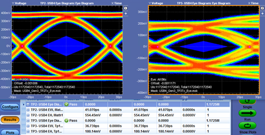
In addition, the Router Host or Router Device Assembly channel budgets are informative in USB4. The good news, however, is when we are performing the compliance test for the USB4 that is performed at TP2 and TP3 test points, the connection or set-up remains same for both TP2 and TP3 test points.

Image 1: USB4 Gen3 (20Gbps) TP2 and TP3 Eye Diagrams
With USB4, there comes new test requirements and corresponding test challenges that need to be addressed. The first step is Transmitter Present Calibration. It's a prerequisite step for transmitter testing. In this test, we capture all 16 preset waveforms, and then measure the Data Deterministic Jitter (DDJ). In USB4, during the Lane Initialization process the receiver will request a change of the preset and might not use the optimal preset for what is being tested. So, it's a good idea to validate and measure all other presets before performing the transmitter testing.
The second test is the Transmitter Equalization Test. Again, this test is related to USB4 presets. The objective of this test is to make sure the Transmitter Equalization falls within the specification limits. The new USB4 method requires three waveforms per preset, compared to the single waveform requirement in PCIe Gen 3/4. That's total of 48 waveforms and therefore is time consuming!

Image 2: V1 w/ both De-Emphasis and Preshoot ON, V2 w/ De-emphasis ON and Preshoot OFF, and V3 w/ De-Emphasis OFF and Preshoot ON
Now let’s discuss how receiver testing and calibration has changed with USB4. First, USB4 receiver calibration needs to be performed for all 5 SJ frequencies. That's a big change compared to USB 3.2 receiver calibration where we used to perform the calibration only at 100 MHz SJ frequency, and then we used to use the same stressed eye calibration for the receiver testing. Also, in USB4 there are two test cases where we need to do the auto-tuning or fine-tuning to meet the stressed eye or total jitter targets. Case 1 is the Low Insertion-Loss (short channel), and case 2 is the Maximum Insertion-Loss (long channel). This is also time consuming.
Next up is USB4 receiver testing or how we can run the traditional Jitter Tolerance test. One of the objectives of the Jitter Tolerance test is to sweep the SJ or amplitude and find the boundaries, or find where the errors start coming. So, to perform this test, we need to first initialize the link using the sideband channel, and then we need to start the BER test. Then we need to keep on monitoring the errors as now the USB4 is using the on-board error counter, rather than the traditional error detector on the BERT. This will be a multi-step process.
Understanding what’s new in USB4 and the new test requirements and challenges will help you navigate the changes to this new standard. The Tektronix USB4 Compliance and Debug solution provide an easy way to validate and characterize the emerging USB4 Router-Host, USB4 Router-Device, and USB4 Hubs as per the USB4 Electrical Compliance Test Specification (CTS) v1.0.
For additional insights, check out the on-demand webinar – USB4 Compliance and Characterization Test Challenges.
USB4™, USB Type-C® and USB-C® are trademarks of the Universal Serial Bus Implementers Forum (USB-IF).


