Kontaktaufnahme
Live-Chat mit Tektronix-Vertretern. Verfügbar von 9 bis 17 Uhr CET Geschäftstage.
Kontaktieren Sie uns telefonisch unter
Verfügbar von 9 bis 17 Uhr CET Geschäftstage.
Download
Laden Sie Handbücher, Datenblätter, Software und vieles mehr herunter:
Feedback
SiC und GaN führen zu neuen Testherausforderungen
Die zunehmende Verwendung von Siliziumkarbid (SiC) und Galliumnitrid (GaN), um die Energieeffizienz von Rechenzentren zu verbessern, die Ladezeit von Elektrofahrzeugen zu verkürzen oder die Effizienz von Antriebssträngen in Elektrofahrzeugen und die Leistungsumwandlung zu optimieren, erfordert neue Ansätze für Validierungstests und ein besseres Verständnis der Geräteleistung. Zu verstehen, wie man die richtigen Messungen durchführt und die richtigen Messinstrumente verwendet, ist der Schlüssel für eine schnellere Markteinführung Ihrer Designs im Bereich Leistungsumwandlung.
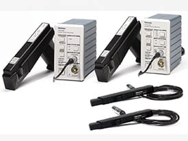
Sichere Validierung von WBG-Halbleitern
Vermeiden Sie häufige Ursachen von Messfehlern mit IsoVu.
Weitere Informationen:
Fallstudie: Panasonic wechselt zur IsoVu-Technologie, um Entwicklungszeiten zu verkürzen
Bewältigung hoher Gleichtaktspannungen
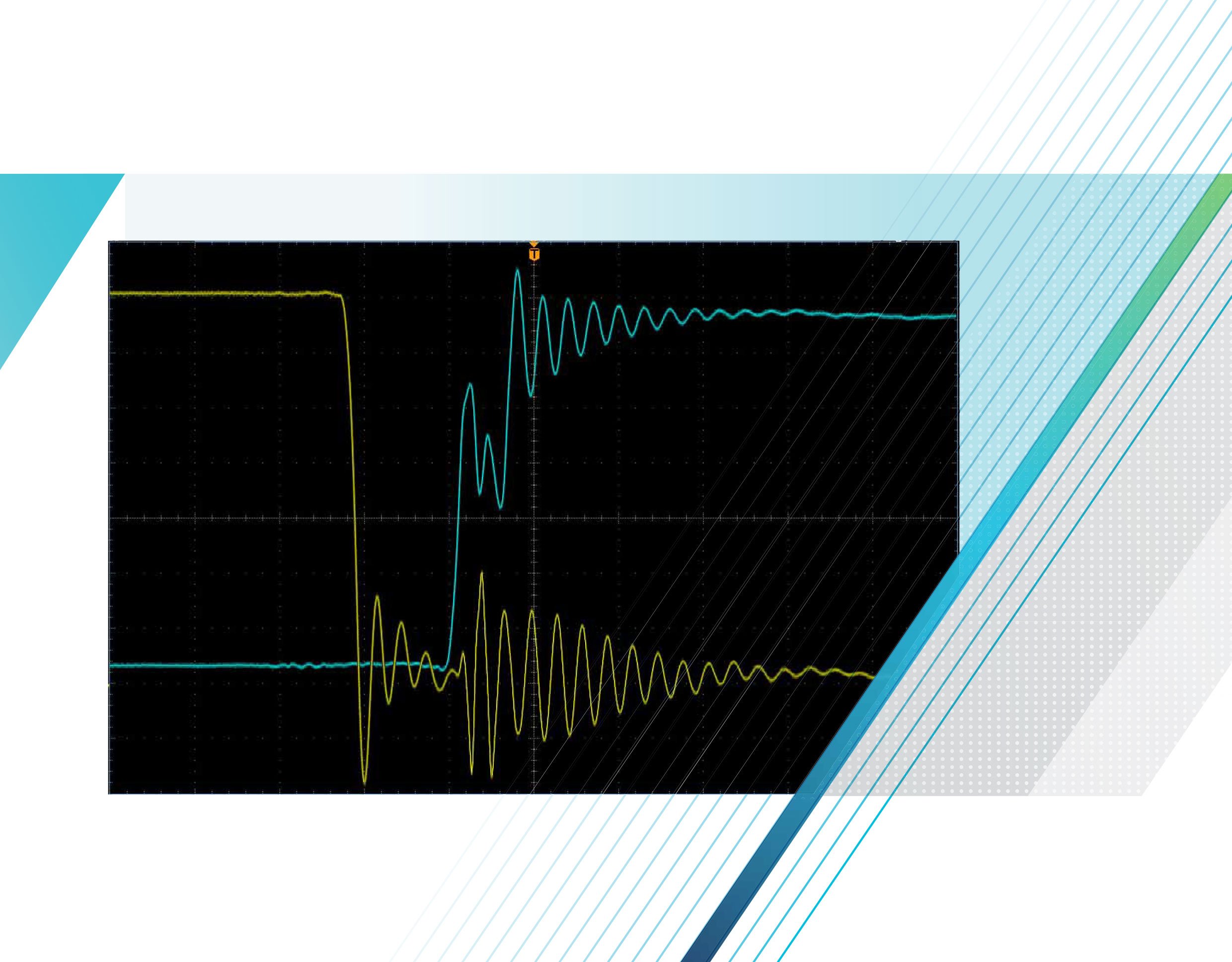
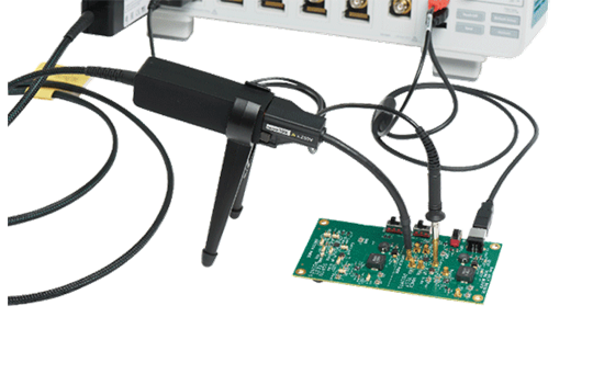
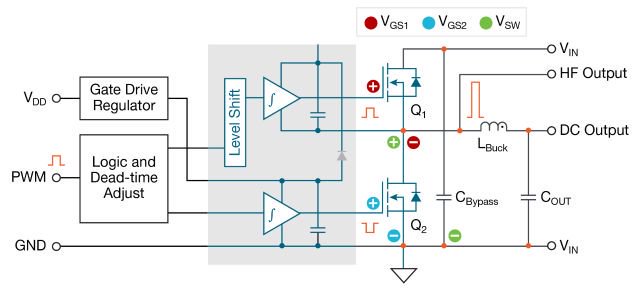
Potentialfreie differenzielle Messungen (wie z. B. bei der Messung von Vgs eines FETs in einem Schaltnetzteil) sind aufgrund der hohen Frequenzen und Gleichtaktspannungen schwierig oder schier unmöglich zu bewältigen, da die üblichen Tastköpfe bei hohen Bandbreiten keine ausreichende Gleichtaktunterdrückung aufweisen. Die niedrige Gleichtaktunterdrückung führt dazu, dass die Messungen durch Gleichtaktfehler dominiert werden, anstatt das tatsächliche differentielle Signal abzubilden. Tektronix hat für diese Art von Problemen eine einzigartige Lösung: Den isolierten IsoVu-Tastkopf, bei dem die Gleichtaktunterdrückung – innerhalb der zum Betrieb von GaN- und SiC-Bauelementen gegebenen Anforderungen – nicht mit der Frequenz abfällt und somit genaue Differentialmessungen ermöglicht. Mit IsoVu können Sie Leitungs-, Totzeit- und Schaltverluste ermitteln und präzise berechnen.
Gleichzeitige Messung mehrerer Steuerungs- und Timing-Signale
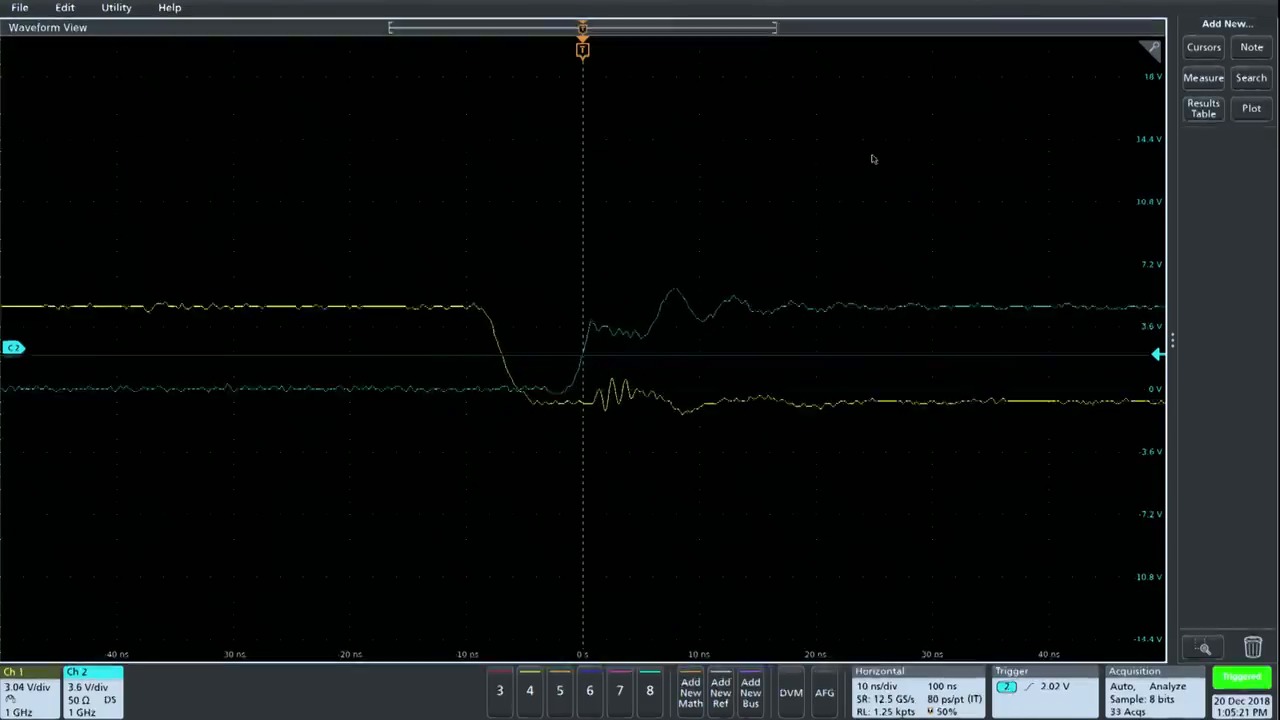
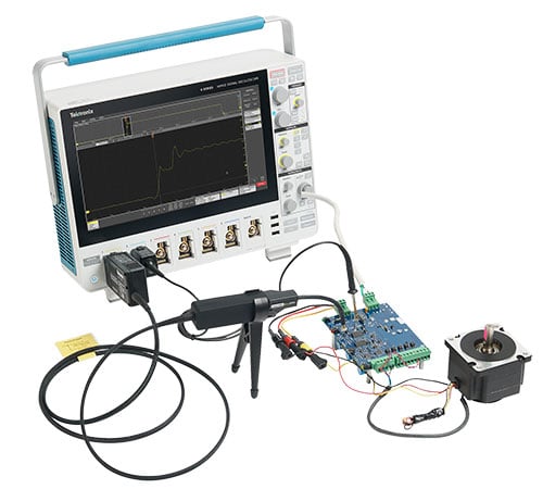
Bei der Bewertung neuer Leistungswandler, die auf SiC- oder GaN-Technologie mit höheren Schaltgeschwindigkeiten basieren, müssen Sie mehrere Signale gleichzeitig überwachen, während Sie an Steuerungen und dem Timing-Schaltkreis für die Stromwandler arbeiten. Dabei messen Sie beispielsweise High-Side Vgs, Low-Side Vgs, High-Side Vds, Low-Side Vgs, Id, IL und Iload, Steuersignale usw.). Außerdem müssen Sie möglicherweise Niederspannungssignale (Vgs) bei vorhandenen Hochspannungssignalen (Vds) messen. Ein Oszilloskop mit hoher Kanalzahl und hoher vertikaler Auflösung kann Ihre Probleme lösen.
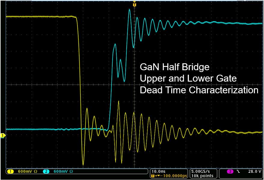
Messpunkte für Zeit- und Steuersignale.
Weitere Informationen:
Prüfung der Stromversorgungs-Sequenzierung mit einem 8-Kanal-Oszilloskop
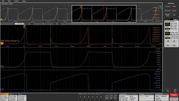
Der Schaltverlust führt zu einer Verlustleistung in einem FET. Signalkurven sind mit farblich gekennzeichneten Markern versehen. Diese zeigen die Messbereiche für Ton, Toff und Total Cycle, was den Werten in der Ergebnisleiste entspricht. Durch die Bedienelemente in der Ergebnisleiste können Sie einfach zwischen den Zyklen hin- und herwechseln.
Weitere Informationen:
Schnellere automatisierte Leistungsmessungen
Eine hohe Auflösung, Mittelwerterfassung und komplexe Wellenformberechnungen sind erforderlich, um genaue, wiederholbare Schalt- und Leitungsverlustmessungen an Hochfrequenz-SiC- und GaN-Bauelementen durchzuführen. Selbst Messungen wie Netzqualität, Oberschwingungen, sicherer Betriebsbereich und Schaltverluste erfordern ein gewisses Maß an Automatisierung im Messprozess, um alle erforderlichen Informationen zu erhalten. Die MSO-Oszilloskope der Serie 5 von Tektronix mit der Option 5-PWR und Messlösungen bieten die automatisierten Messfunktionen, die Sie während der Designphase und beim Debuggen benötigen.
Schaltverlustmessungen und -analysen
Angesichts der Erfordernis, die Energieeffizienz zu verbessern und die Betriebszeit von batteriebetriebenen Geräten zu verlängern, wechseln Ingenieure für ihre Designs von herkömmlichen Siliziumbatterien zu SiC und GaN. Die Fähigkeit, Leistungsverluste zu analysieren und die Effizienz der Stromversorgung zu optimieren, ist wichtiger denn je. Einer der Schlüsselfaktoren für die Effizienz ist der Verlust in Schaltgeräten. Ein typisches Schaltnetzteil hat beispielsweise einen Wirkungsgrad von etwa 87 %, was bedeutet, dass 13 % der Eingangsleistung innerhalb des Netzteils abgeführt werden, hauptsächlich als Abwärme. Von diesem Verlust wird ein erheblicher Teil in den Schaltelementen umgewandelt, normalerweise MOSFETs oder IGBTs. Mit den MSO-Oszilloskopen der Serien 5 und 6 und der automatisierten Leistungsanalysesoftware von Tektronix ist es ganz einfach, Schaltverlustmessungen durchzuführen.
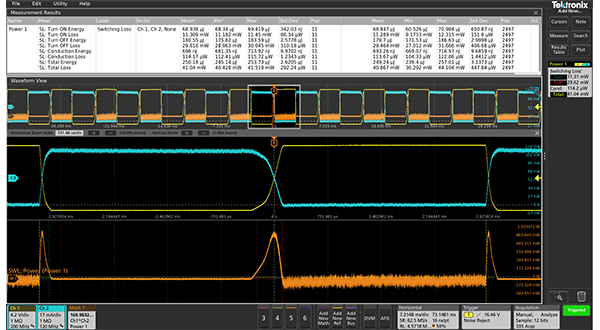
Automatische Schaltverlustmessung.
Weitere Informationen:
Messen der Schaltverluste an Netzteilen mit einem Oszilloskop

Ressourcen