Kontaktaufnahme
Live-Chat mit Tektronix-Vertretern. Verfügbar von 9 bis 17 Uhr CET Geschäftstage.
Kontaktieren Sie uns telefonisch unter
Verfügbar von 9 bis 17 Uhr CET Geschäftstage.
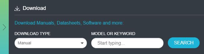
Download
Laden Sie Handbücher, Datenblätter, Software und vieles mehr herunter:
Feedback
TekExpress PCI Express Transmitter Compliance and Validation Software Application Help
This document provides the operating instructions for the TekExpress PCI Express Transmitter Compliance and Validation Software Application, for DPS/DPO/DSA/MSO70000C, D, DX, SX Series Oscilloscopes.
Dieses Handbuch bezieht sich auf:
DPO77002SX, DPS77004SX, DPS75904SX, DPS75004SX, DPO75002SX, DPO73304SX, DPO72304SX, DPO71604SX, DPO71304SX, DPO73304DX, MSO73304DX, DPO72504DX, MSO72504DX, DPO72304DX, MSO72304DX, DPO73304D, DSA73304D, DPO72504D, DSA72504D, DPO72004C, DSA72004C, MSO72004C, DPO71604C, DSA71604C, MSO71604C, DPO71254C, DSA71254C, MSO71254C, DPO70804C, DSA70804C, MSO70804C, DPO70604C, DSA70604C, MSO70604C, DPO75902SX, DPO72004SX
By downloading, you agree to the terms and conditions of the Manuals Download Agreement.Manuals Download Agreement
ATTENTION: please read the following terms and conditions carefully before downloading any documents from this website. By downloading manuals from Tektronix' website, you agree to the following terms and conditions:
Manuals for Products That Are Currently Supported:
Tektronix hereby grants permission and license to owners of Tektronix instruments to download and reproduce the manuals on this website for their own internal or personal use. Manuals for currently supported products may not be reproduced for distribution to others unless specifically authorized in writing by Tektronix, Inc.
A Tektronix manual may have been revised to reflect changes made to the product during its manufacturing life. Thus, different versions of a manual may exist for any given product. Care should be taken to ensure that one obtains the proper manual version for a specific product serial number.
Manuals for Products That Are No Longer Supported:
Tektronix cannot provide manuals for measurement products that are no longer eligible for long term support. Tektronix hereby grants permission and license for others to reproduce and distribute copies of any Tektronix measurement product manual, including user manuals, operator's manuals, service manuals, and the like, that (a) have a Tektronix Part Number and (b) are for a measurement product that is no longer supported by Tektronix.
A Tektronix manual may be revised to reflect changes made to the product during its manufacturing life. Thus, different versions of a manual may exist for any given product. Care should be taken to ensure that one obtains the proper manual version for a specific product serial number.
This permission and license does not apply to any manual or other publication that is still available from Tektronix, or to any manual or other publication for a video production product or a color printer product.
Disclaimer:
Tektronix does not warrant the accuracy or completeness of the information, text, graphics, schematics, parts lists, or other material contained within any measurement product manual or other publication that is not supplied by Tektronix or that is produced or distributed in accordance with the permission and license set forth above.
Tektronix may make changes to the content of this website or to its products at any time without notice.
Limitation of Liability:
TEKTRONIX SHALL NOT BE LIABLE FOR ANY DAMAGES WHATSOEVER (INCLUDING, WITHOUT LIMITATION, ANY CONSEQUENTIAL OR INCIDENTAL DAMAGES, DAMAGES FOR LOSS OF PROFITS, BUSINESS INTERRUPTION, OR FOR INFRINGEMENT OF INTELLECTUAL PROPERTY) ARISING OUT OF THE USE OF ANY MEASUREMENT PRODUCT MANUAL OR OTHER PUBLICATION PRODUCED OR DISTRIBUTED IN ACCORDANCE WITH THE PERMISSION AND LICENSE SET FORTH ABOVE.
Read Online
SETTING UP THE TEST ENVIRONMENT
SETUP PANEL: CONFIGURE THE TEST SETUP
- DUT: Set DUT settings
- Filter setup dialog box
- Automated DUT control setup
- NI USB 6501 DUT Controller Support
- Multiple-session run
- Test Selection: Select the tests
- Acquisitions: Set waveform acquisition settings
- Set acquisition options
- Set acquisition waveform save options
- Set acquisition waveform source for prerecorded waveform files
- Set acquisition signal source
- No. of Acquisitions
- Jitter Test Acquisition
- Analysis Tool
- Configuration: Set measurement limits for tests
- Preferences: Set the test run preferences
SCPI COMMANDS
- About SCPI command
- Socket configuration for SCPI commands
- Set or query the device name of application
- Set or query the suite name of the application
- Set or query the test name of the application
- Set or query the version name of the application
- Set or query the general parameter values
- Query the available devices in the DUT panel of the application
- Query the available suites for the selected device
- Query the list of available tests of the application
- Query the available version names of the application
- Query the list of available instruments based on the specified instrument type
- Set or query the IP address of the instrument based on the specified instrument type
- Query the information of the generated report file
- Query the information of the generated waveform files
- Query the information of the generated image files
- Query the active TekExpress application name
- Set or query the DUTID of application
- Sets or query the acquire mode status
- Set or query the execution mode status
- Generate the report for the current session
- Query the value of specified report header field in the report
- Query the value of specified result detail available in report summary/details table
- Restore the setup to default settings
- Save the setup
- Save the settings to a specified session
- Open the setup from a specified session
- Query the current setup file name
- Run/stop/pause/resume the selected measurements execution in the application
- Query the current measurement execution status
- Query whether the current setup is saved or not saved
- Query the status of the previous command execution
- Query the last error occurred
- Set or query the popup details
- Sets or query the limit values in the limits editor window
- Set or query the waveform file recalled for the specified test name and acquire type
- Set or query the enable/disable status of Verbose function
- Set or query the View report after generating option status
- Returns the report as XML string
- Copies all the images from current run session to the given destination location
- Selects the specified test(s) and deselect all other tests
- Returns the complete information about the selected test
- Set the default session
- Save the run/config sessions
- Load the run/config session
- Delete the run/config session
- Run the run/config saved session
- Query the available list in the run/config session
- Query the current run/config session
- Override the run/config session
- Exit or close the application
- Examples
Welcome
The TekExpress® PCI Express Automated Test Solution Software application (referred to as TekExpress PCIe or PCIe in the rest of the document) provides an automated, simple, and efficient way to test PCI Express interfaces and devices consistent to the requirements of the PCI Express specifications.
- New features from current release:
- Support for Gen6 PWJ measurements using PAMJET tool.
- Integration of Automated Scope noise characterization and compensation for Gen6.
- Integration of CTLE optimization for Gen6 jitter measurements.
- Support for Mini-Circuits RF Switch for Gen1-5 testing.
- Improvement in Gen6 Preset Test feature.
- Updated Gen6 Preset tests limits as per latest spec.
- Support for Intel Clock Jitter Tool (CJT) for Ref Clock testing.
- Support for Sigtest Phoenix v5.1.04 for Gen5 CEM Signal and preset tests.
- Existing Features:
- PCIe CEM TX Testing
- Supports Add-In-Card and System Board device types
- Supports Gen1, Gen2, Gen3, Gen4, and Gen5 versions
- Supports Signal Quality Test for all generations
- Supports Preset Test for Gen3, Gen4, and Gen5 generations
- Supports Pulse Width Jitter Test for Gen4 and Gen5 Add-In-Card device type
- PCIe Base TX testing
- Supports both PCIe Gen5 Base Tx Common Clock & SRIS architecture
- Supports Gen3, Gen4, and Gen5 versions
- Supports Jitter & Voltage Signal Quality Test and Preset Test for all generations
- U.2 (SFF-8639) TX Testing
- Supports Gen3 Host and Module device types
- M.2 TX Testing
- Supports Gen3 M.2 Add-In-Card and Host device types
- PCIe Ref Clock TX Testing
- Supports Gen3, Gen4, and Gen5 versions of CXL Base, CEM Card and CEM Host type device testing.
- PCIe CXL Testing
- Supports Gen1 to Gen5 Ref Clock Jitter and Signal Integrity measurements
- Tektronix ATI (200GS/s) channel support for CEM, Base Spec, U.2, M.2 and Ref clock testing for all generations (Not applicable for CEM System Board Gen1-4 and U.2 Host Gen3)
- Supports channel embed and de-embed filter files
- Supports de-embedding on each ATI channel using separate filter files
- Supports Intel CJT, Skyworks Clock Jitter tool or DPOJet for ref clock analysis
- Supports traditional break-out channel de-embedding & SigTest CTLE (for uncorrelated jitter measurements only)
- Automated De-skew and attenuation for ATI Channels
- Supports single and multiple acquisition for CEM Gen4 and Gen5
- Trigger type support for Gen3, Gen4, and Gen5 (Auto/Width/Edge)
- Automated toggling of the DUT to switch presets for CEM, U.2, and M.2 device types using AWG/AFG/GRL PHY Test Controller/NI USB 6501 DUT Controller.
- Simple push button, enabling the users to manually toggle PCIe presets from AWG/AFG
- Support for Gen4 and Gen5 dataclock pattern custom toggle index in non standard devices.
- RF Switch support to test the x12 and x16 lanes using Keithley and Gigatronics switches respectively
- Fully automated General, Jitter, Composite Eye, Transition Eye, and Non Transition Eye measurements
- Provides individual or group test selection by using a tree-structure menu
- Supports preset test selection for all device types
- Integrated Intel Sigtest for fully automated waveform analysis
- Supports parallel execution of measurements using multiple instances of SigTest to accelerate the test analysis speed
- Deploys recommended versions of SigTests for analysis
- Sigtest Phoenix v5.1.03: PCIe Gen5 CEM Spec
- Sigtest v4.0.52: PCIe Gen4 CEM Spec, Gen4 and Gen5 Base Spec
- Sigtest v4.0.42: PCIe Gen3 Base spec
- Sigtest v3.2.0.3: PCIe Gen3 CEM Spec
- Option to browse and select different Sigtest versions and templates for debug
- Support Sigtest run in silent mode (Not applicable for Sigtest v3.2.0.3)
- Built-in reporting features:
- Provides a Pass/Fail summary table
- Provides generation specific pass/fail status summary table
- Provides margin details on each test
- Provides a consolidated report for all tests
- Supports .pdf, .mht and .csv formats
- Provides Tektronix Method of Implementation (MOI) for PCIe testing Run-time setup instructions with image pop-ups and reference illustrations for each test execution
- Provides both an automation solution (for compliance) and DPOJET (for debug)
- TekExpress setup files in-line with PCI-SIG Compliance Workshop
- Supports SCPI commands to remotely communicate with the TekExpress application
- 33 GHz Oscilloscope supports CEM Gen5 TX testing using Tekconnect channels.
- Supports Eye Diagram plots for Base Spec through DPOJET
- Support for PCIe Gen6 Base Spec TX signal quality test using PAMJet and DPOJet analysis tools.
- Support for PCIe Gen6 Base Spec TX preset test.
- Support for Base Spec Gen6 signal validation using PAMJet tool.
- Improved UI look and feel.
- PCIe CEM TX Testing
Getting help and support
Product documents
Use the product documents for more information on the application functions, understand the theory of operation, how to remotely program or operate the application, and do other tasks.
| To learn about | Use this document |
|---|---|
| How to use the application How to remotely control the instrument |
TekExpress PCI Express Help PDF version of this document can be downloaded from http://www.tek.com/downloads Compiled HTML (CHM) version is integrated with the application. Press F1 key from the keyboard to start the help. Tektronix Part Number: 077-xxxx-xx |
Conventions
This application help uses the following conventions:
- The term "Application," and "Software" refers to the TekExpress PCI Express application.
- The term “DUT” is an abbreviation for Device Under Test.
- The term “select” is a generic term that applies to the two methods of choosing a screen item (button control, list item): using a mouse or using the touch screen.
- A Note identifies important information.
| Icon | Description |
|---|---|
 | This icon identifies important information |
 | This icon identifies conditions or practices that could result in loss of data. |
 | This icon identifies additional information that will help you use the application more efficiently. |
Technical support
Tektronix values your feedback on our products. To help us serve you better, please send us your suggestions, ideas, or comments on your application or oscilloscope. Contact Tektronix through mail, telephone, or the Web site. See Contacting Tektronix at the front of this document for contact information.
When you contact Tektronix Technical Support, please include the following information (be as specific as possible):
General information
- All instrument model numbers
- Hardware options, if any
- Modules used
- Your name, company, mailing address, phone number, FAX number
- Please indicate if you would like to be contacted by Tektronix about your suggestion or comments.
Application specific information
- Software version number
- Description of the problem such that technical support can duplicate the problem
- If possible, save the setup files for all the instruments used and the application
- If possible, save the TekExpress setup files, log.xml, *.TekX (session files and folders), and status messages text file
Getting started
Hardware requirements
Minimum system requirements
The following table shows the minimum system requirements needed for an oscilloscope to run TekExpress PCI Express.
|
Component |
Requirement |
|---|---|
| Oscilloscope | See Instruments and accessories required |
| Processor | Same as the oscilloscope |
| Operating system | Microsoft Windows 10 (64-bit only) Required Windows 10 user account settings |
| Memory | Same as the oscilloscope |
| Hard disk | Same as the oscilloscope |
| Display | Same as the oscilloscope |
| Firmware | Tekscope for MSO/DSA/DPO70000C, D, DX, SX |
| Software |
|
Readme TekExpress PCI Express.txt file at C:\Program Files\Tektronix\TekExpress\TekExpress PCI Express
Instruments and accessories required
The following table lists the instruments and accessories required for TekExpress PCI Express application.
| Instrument/Accessory | Model number |
|---|---|
| Oscilloscope |
MSO70604 , DPO/MSO70604C (Gen1 testing only) MSO708041, DPO/MSO70804C (Gen1 and Gen2 testing) MSO712541, DPO/MSO71254C (Gen1, Gen2, and Gen3 testing only) MSO716041, DPO/MSO71604C (Gen1, Gen2, and Gen3 testing) MSO720041, DPO/MSO72004C (Gen1, Gen2, and Gen3 testing) DPO/MSO72304DX (Gen1, Gen2, and Gen3 testing) DPO/DSA72504D ( Gen1, Gen2, Gen3, and Gen4 testing) DPO/DSA73304D (all generation testing) DPO/MSO72304DX (Gen1, Gen2, and Gen3 testing) DPO/MSO72504DX (all generation testing) DPO/MSO73304DX (Gen1, Gen2, Gen3, and Gen4 testing) DPO71304SX (Gen1, Gen2, and Gen3 testing) DPO71604SX (Gen1, Gen2, and Gen3 testing) DPO72304SX (Gen1, Gen2, and Gen3 testing) DPO73304SX All Generation Testing DPO75002SX [Standalone or 2 Stack] All Generation Testing DPO75902SX [Standalone or 2 Stack] All Generation Testing DPO77002SX [Standalone or 2 Stack] All Generation Testing |
| Arbitrary Function Generator (AFG) (for automatic test pattern toggling) | Tektronix AFG3252, AFG3252C, AFG31252 |
| Arbitrary Waveform Generator (AWG) (for automatic test pattern toggling) |
|
|
RF Switch |
|
| GRL PCIE34 Controller for automatic test pattern toggling and DUT power cycle |
Part number : GRL-PCIE34-P1 Contact GRL at http://[email protected] for support and http://[email protected] to request for a quote. |
| NIUSB-6501 for automatic toggling of Gen4 DUTs |
Part Number: 779205-01 Discuss product recommendations, quote products, and place an order.
|
| Other devices |
|
P7513, P7513A, P7516, P7520A, P7625, P7630, P7633, P7713, P7716, P7720 with respective tips
TCA-SMA
(Max 18 GHz)
TCA-292D
(Max 33 GHz)
P7500
(Max 20 GHz)
P7700
(Max 20 GHz)
P7600
(Max 33 GHz)
Differential probes
PCI Express
Speed
Minimum oscilloscope bandwidth
2.5 GT/s
6 GHz
√ √ √ √ √ 5.0 GT/s
12.5 GHz
√ √ √ √ √ 8.0 GT/s
13 GHz √ √ √ √ √ 16.0 GT/s
25 GHz
√
√ 32.0 GT/s
50 GHz
√
100 MHz RefClk
5 GHz
√ √ √ √ √
Software requirements
Downloading and installing the software
Complete the following steps to download and install the latest TekExpress PCI Express application.
- Go to www.tek.com.
- Click Downloads. In the Downloads menu, select DOWNLOAD TYPE as Software and enter the application name in the MODEL OR KEYWORD field and click SEARCH.

- Select the latest version of software and follow the instructions to download the software. Copy the executable file into the oscilloscope.
- Double-click the executable and follow the on-screen instructions.
The software is installed at
C:\Program Files\Tektronix\TekExpress\TekExpress PCI Express. - Select from the Oscilloscope menu, to open the application.
Activate the license
Activate the license using the Option Installation wizard in the TekScope application:
- In the TekScope application menu bar, click . The TekScope Option Installation wizard opens.
- Push the F1 key on the oscilloscope keyboard to open the Option Installation help topic.
- Follow the directions in the help topic to activate the license.
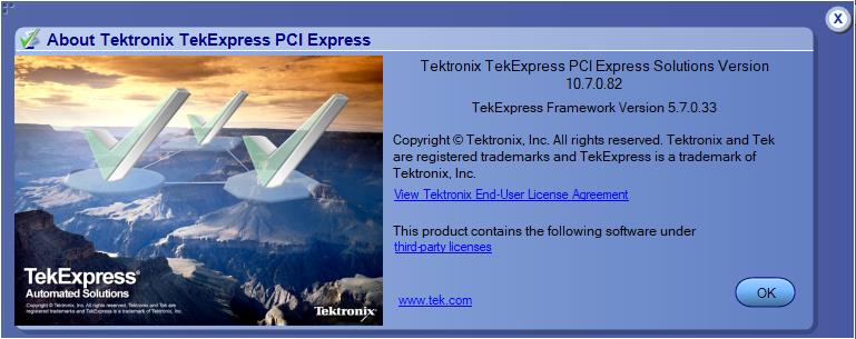
View software version and license key details
To view version information of the application, click Options > About TekExpress.
Setting up the test environment
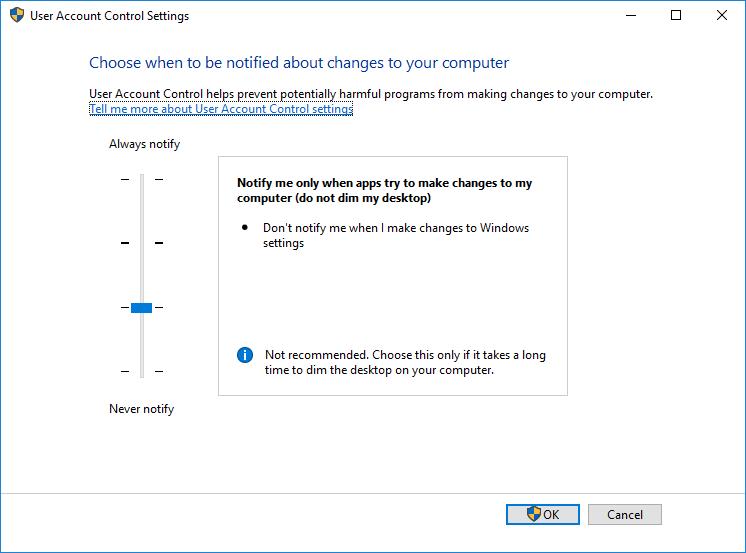
Windows 10 user account settings
Windows 10 instruments need to have the User Account Control Settings set to Never Notify. To set User Account Control Settings:
-
Go to Control Panel > User Accounts > Change User Account Control settings.
-
Set the sliding control to Always notify as shown in the image, and click OK.
See also
Install the software
Use the following steps to install PCI Express software on any compatible instrument running Microsoft Windows 10 (64-bit). See Minimum System Requirements for details.
- Close all applications (including the TekScope application).
- Go to the www.tek.com Web site and search for TekExpress PCI Express to locate the installation file. Download the file
TekExpress_PCIe_Deployment_Package.exe. - Copy or download the PCIe installer file to the oscilloscope.
- Double-click the installer .exe file to extract the installation files and start the InstallShield Wizard. Follow the on-screen instructions. The software installs in the following location:
C:\Program Files\Tektronix\TekExpress\TekExpress PCI Express
- The installer updates the TekScope Analyze menu to include the installed options.
See also
Set application file permissions
Before you run tests for the first time, do the following:
- Understand where your test files are stored on the instrument. After you install and start TekExpress PCIe, it creates the following folders on the oscilloscope:
-
\My Documents\My TekExpress\PCI Express -
\My Documents\My TekExpress\PCI Express\Untitled Session
Every time you start TekExpress PCIe, an
Untitled Sessionfolder is created in thePCIefolder. TheUntitled Sessionfolder is automatically deleted when you exit thePCIeapplication. To preserve your test session files, save the test setup before exiting the TekExpress application.CAUTION:Do not modify any of the session files or folders because this may result in loss of data or corrupted session files. Each session has multiple files associated with it. When you save a session, a .TekX file, and a folder named for the session that contains associated files, is created on the oscilloscope X: drive.
-
- Map the shared My TekExpress folder as X: (X drive) on the instruments used in test setups running Microsoft Windows Operating System.
The My TekExpress folder has the share name format
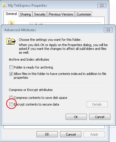
<domain><user ID>My TekExpress. Or, if the instrument is not connected to a domain, the share name format is<instrument name><user ID>My TekExpress. This shared folder is used to save the waveform files and is used during other file transfer operations.Note:If the X: drive is mapped to any other shared folder, the application will display a warning message asking you to disconnect the X: drive manually. - Make sure that the My TekExpress folder (Drive X:) has read and write access:
- Right-click the folder and select Properties.
- Select the General tab and then click Advanced.
- In the Advanced Attributes dialog box, make sure that the option Encrypt contents to secure data is NOT selected (not checked).
- See the prerun checklist before you run a test.
See also
About setting up tests
Set up tests using the tabs in the Setup panel. Settings in the DUT tab use a top-down, left-to-right logic flow, so that any parameter that affects or acts as a filter for other parameters appears either to the top of or to the left of the affected parameters.
Tests are saved when you save a test setup. To avoid overwriting test results, remember to assign a unique name to the test either before running it or immediately after.
See also
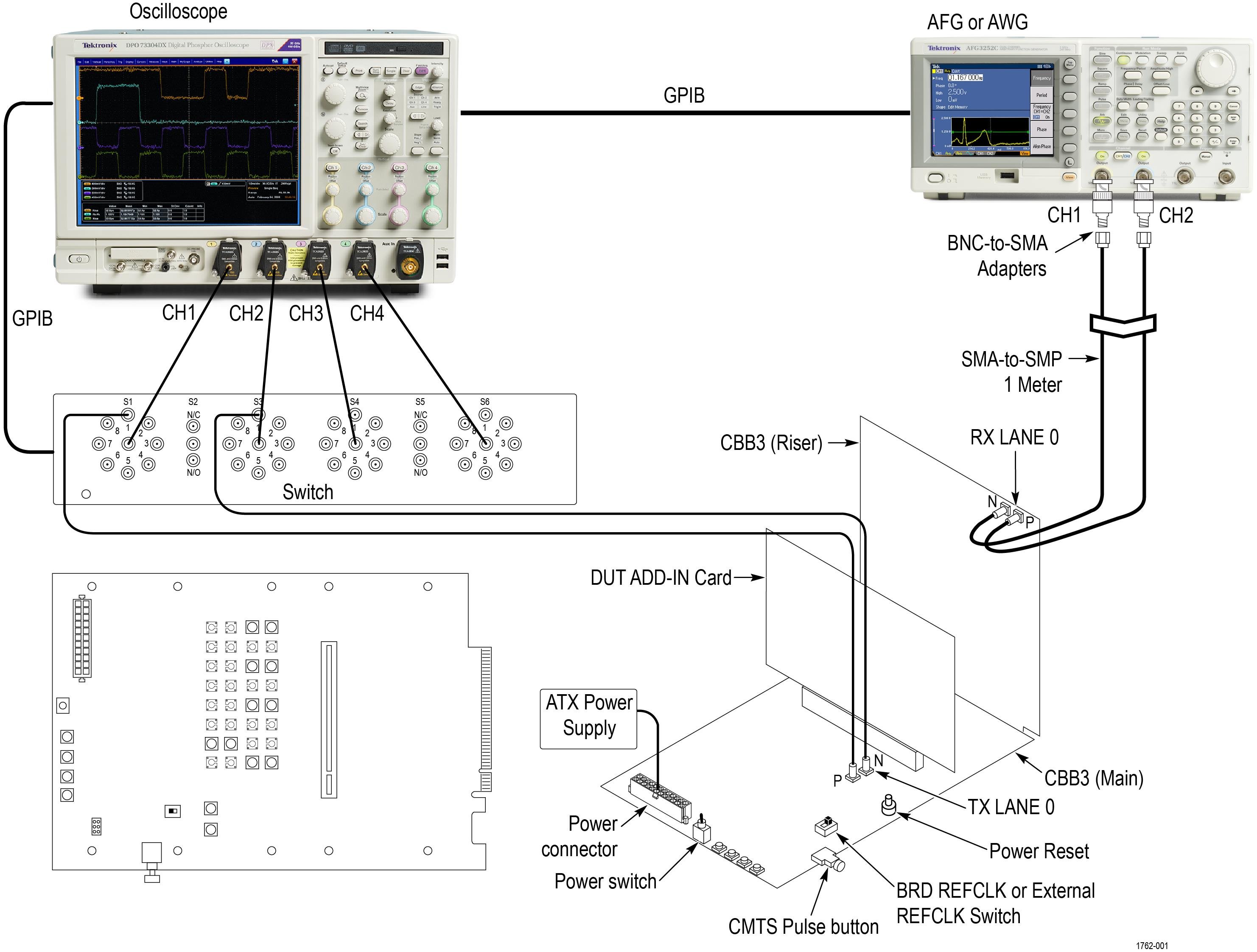
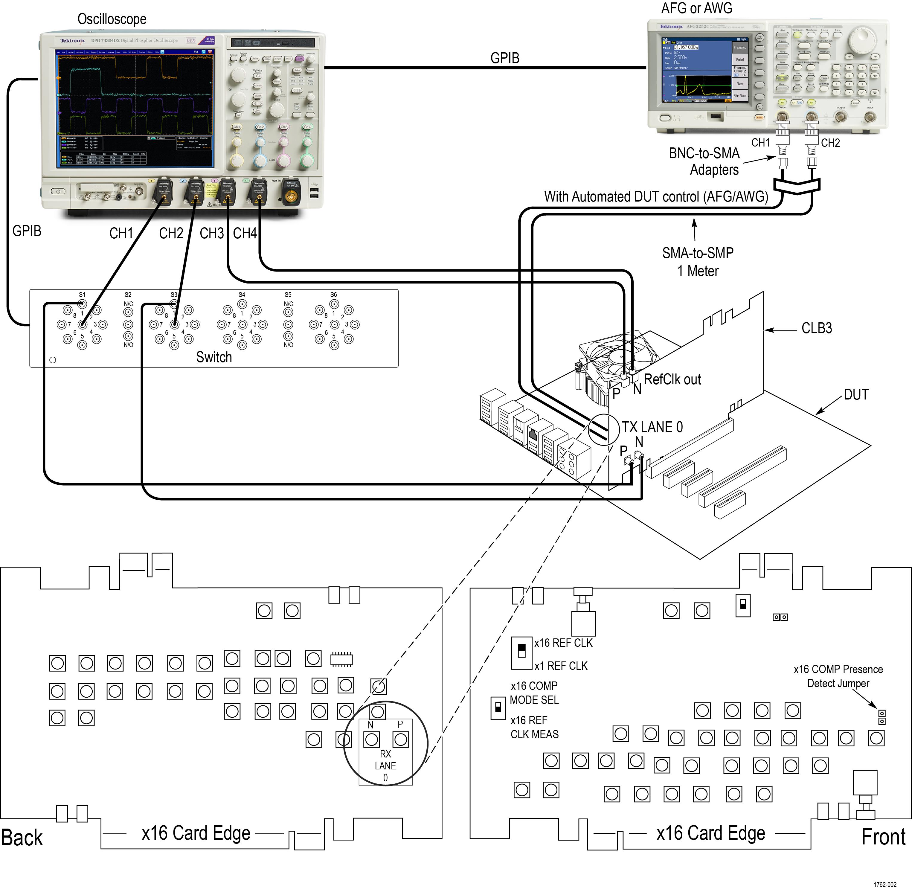
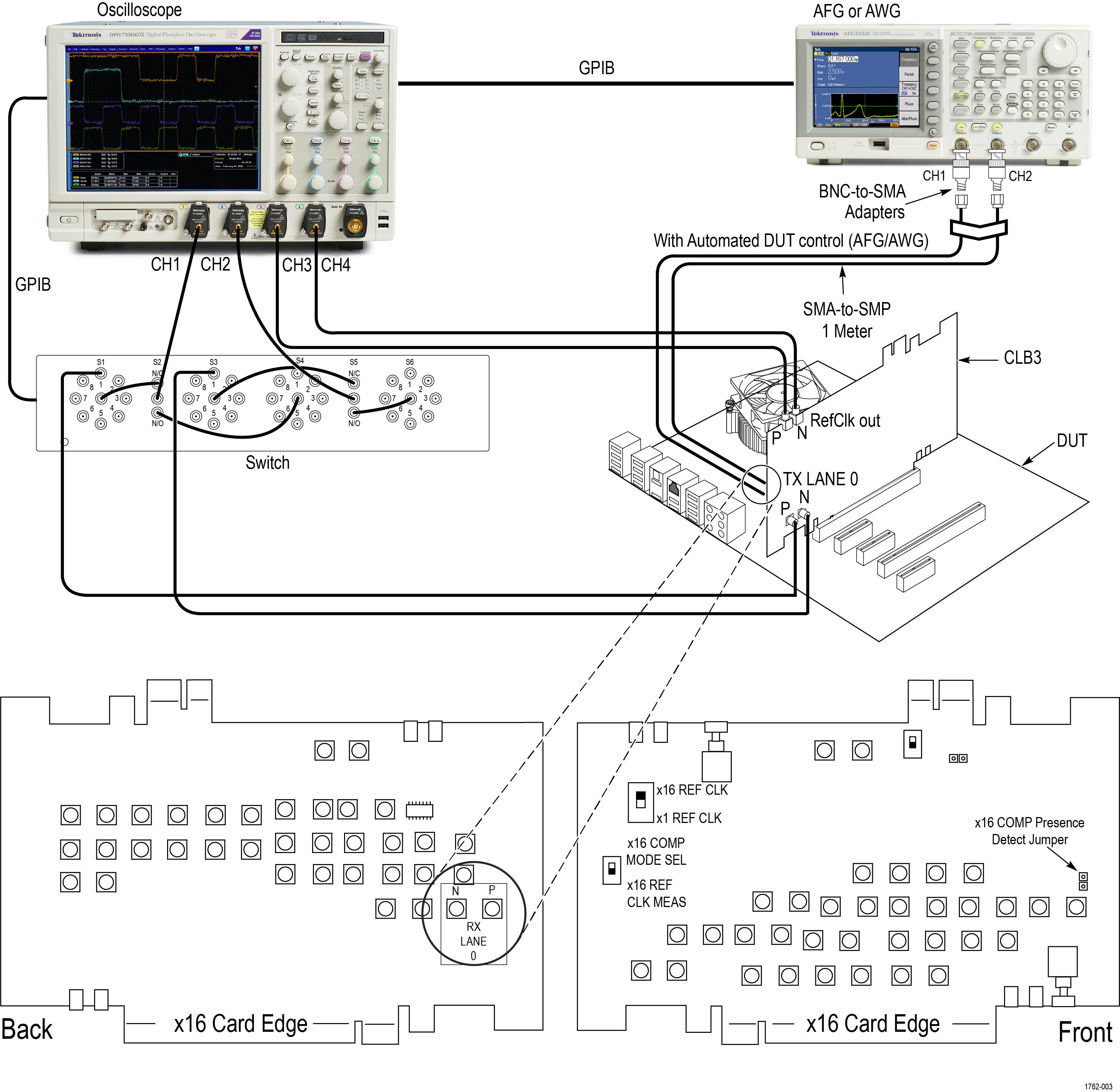
Equipment connection setup
Click the Setup > Test Selection > Schematic button to open a PDF file that shows the compliance test setup diagrams (instrument, DUT, and cabling) for supported testing configurations.
See also
Equipment connection setup through switch system
| Switch: DUT Lane to Signal connection mapping | |||
|---|---|---|---|
|
TX LANE 0 P | S1 (relay) > Signal 1 |
TX LANE 0 N | S3 > Signal 1 |
|
TX LANE 1 P | S1 > Signal 2 |
TX LANE 1 N | S3 > Signal 2 |
|
TX LANE 2 P | S1 > Signal 3 |
TX LANE 2 N | S3 > Signal 3 |
|
TX LANE 3 P | S1 > Signal 4 |
TX LANE 3 N | S3 > Signal 4 |
|
TX LANE 4 P | S1 > Signal 5 |
TX LANE 4 N | S3 > Signal 5 |
|
TX LANE 5 P | S1 > Signal 6 |
TX LANE 5 N | S3 > Signal 6 |
|
TX LANE 6 P | S1 > Signal 7 |
TX LANE 6 N | S3 > Signal 7 |
|
TX LANE 7 P | S1 > Signal 8 |
TX LANE 7 N | S3 > Signal 8 |
|
TX LANE 8 P | S4 > Signal 1 |
TX LANE 8 N | S6 > Signal 1 |
|
TX LANE 9 P | S4 > Signal 2 |
TX LANE 9 N | S6 > Signal 2 |
|
TX LANE 10 P | S4 > Signal 3 |
TX LANE 10 N | S6 > Signal 3 |
|
TX LANE 11 P | S4 > Signal 4 |
TX LANE 11 N | S6 > Signal 4 |
|
TX LANE 12 P | S4 > Signal 5 |
TX LANE 12 N | S6 > Signal 5 |
|
TX LANE 13 P | S4 > Signal 6 |
TX LANE 13 N | S6 > Signal 6 |
|
TX LANE 14 P | S4 > Signal 7 |
TX LANE 14 N | S6 > Signal 7 |
|
TX LANE 15 P | S4 > Signal 8 |
TX LANE 15 N | S6 > Signal 8 |
| Switch: DUT Lane to Signal connection mapping | |||
|---|---|---|---|
|
TX LANE 0 P | S1 (relay) > Signal 1 |
TX LANE 0 N | S3 > Signal 1 |
|
TX LANE 1 P | S1 > Signal 2 |
TX LANE 1 N | S3 > Signal 2 |
|
TX LANE 2 P | S1 > Signal 3 |
TX LANE 2 N | S3 > Signal 3 |
|
TX LANE 3 P | S1 > Signal 4 |
TX LANE 3 N | S3 > Signal 4 |
|
TX LANE 4 P | S1 > Signal 5 |
TX LANE 4 N | S3 > Signal 5 |
|
TX LANE 5 P | S1 > Signal 6 |
TX LANE 5 N | S3 > Signal 6 |
|
TX LANE 6 P | S1 > Signal 7 |
TX LANE 6 N | S3 > Signal 7 |
|
TX LANE 7 P | S1 > Signal 8 |
TX LANE 7 N | S3 > Signal 8 |
|
TX LANE 8 P | S4 > Signal 1 |
TX LANE 8 N | S6 > Signal 1 |
|
TX LANE 9 P | S4 > Signal 2 |
TX LANE 9 N | S6 > Signal 2 |
|
TX LANE 10 P | S4 > Signal 3 |
TX LANE 10 N | S6 > Signal 3 |
|
TX LANE 11 P | S4 > Signal 4 |
TX LANE 11 N | S6 > Signal 4 |
|
TX LANE 12 P | S4 > Signal 5 |
TX LANE 12 N | S6 > Signal 5 |
|
TX LANE 13 P | S4 > Signal 6 |
TX LANE 13 N | S6 > Signal 6 |
|
TX LANE 14 P | S4 > Signal 7 |
TX LANE 14 N | S6 > Signal 7 |
|
TX LANE 15 P | S4 > Signal 8 |
TX LANE 15 N | S6 > Signal 8 |
| Note:GPIB is the recommended interface to execute the switch matrix commands.
|
Test setup overview
Test setup includes acquisition and configuration parameters. You can also select report options when setting up tests. Use the options in the Setup panel and Reports panel to select and configure tests.
- Set up equipment.
- Do the prerun checklist.
- Set DUT parameters.
- Select one or more tests.
- Select acquisitions.
- Configuration test parameters.
- Set test measurement notification options.
- Select report options.
See also
Prerequisite
Compensate the signal path
- Power on and wait for the instrument to complete its warm up period before continuing with this procedure.
- Disconnect any probes you have connected to the input channels.
- Set the instrument to Menu mode.
- Select Instrument Calibration from the Utilities menu.
- Note any instructions that appear in the resulting control window.
- Click Run SPC to begin the procedure. The procedure may take several minutes to complete.
- Verify that the Status changes to Compensated after the procedure is complete. If the Calibration Status field indicates anything other than Compensated, see Signal Path Compensation Status for information on the readout and recommended action.
| Note:When making measurements at vertical scale settings less than or equal to 5 mV, you should perform the signal path compensation at least once a week. Failure to do so may result in the instrument not meeting warranted performance levels at those volts/div settings.
|
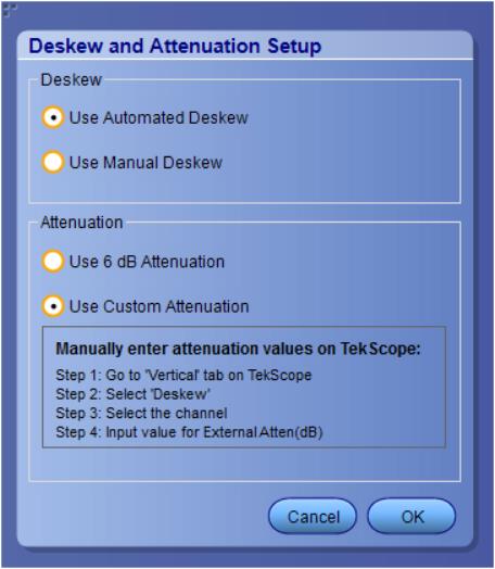
Deskew and Attenuation
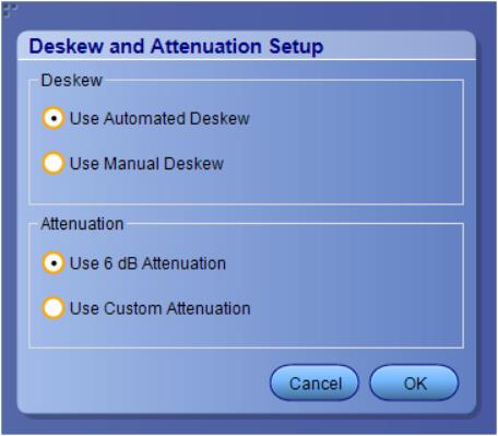
Deskew:
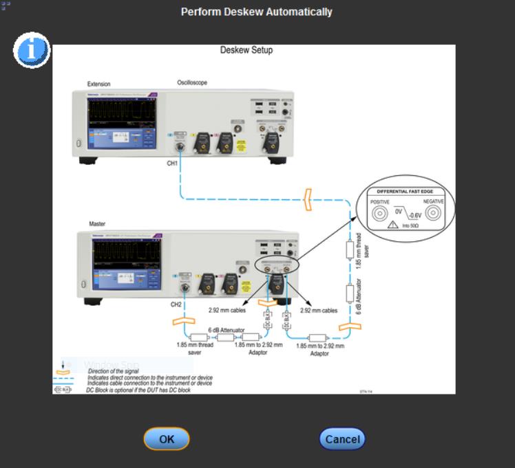
- Use Automated Deskew (Which is selected by default) automated deskew works in the following way:
- By selecting the automated deskew, the application runs the deskew operation before acquiring the DUT signal.
- Deskew will be performed to remove the skew of the setup which is primarily the cable set and oscilloscope channel. Deskew requires a low-frequency signal with a small rise/fall time. Both these requirements are fulfilled by the fast edge on the oscilloscope.
- During deskew the other end of the cable connected to the fixture/ISI board is connected to the fast edge. Fast edge has a skew of less than 1 ps. If the +ve and -ve channels of fast edge are phase-matched, the user can ensure that the setup (cable+oscilloscope channel) has a skew of less than 1 ps.
Figure 1. Deskew popup window
- Use Manual Deskew Manual
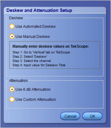
- Use 6 dB Attenuation (Which is selected by default).
- Use Custom Attenuation.
Running tests
After selecting and configuring tests, review the Prerun checklist and then click Start to run the tests. While tests are running, you cannot access the Setup or Reports panels. To monitor the test progress, switch back and forth between the Status panel and the Results panel.
The application displays a report when the tests are complete. While the tests are running, other applications may display windows in the background. The TekScope application takes precedence over other applications, but you can switch to other applications by using the Alt + Tab key combination. To keep the TekExpress PCIe application on top, select Keep On Top from the TekExpress Options menu.
See also
Prerun checklist
Do the following before you click Start to run a test. If this is the first time you are running a test on a setup, refer to the information in Before you click start.
- Make sure that all the required instruments are properly warmed up (approximately 20 minutes).
- Perform Signal Path Compensation (SPC):
- On the oscilloscope main menu, select the Utilities menu.
- Select Instrument Calibration.
- Verify that the application is able to find the DUT. If it cannot, perform a search for connected instruments:
- In PCIe, select the Setup panel and then click the Test Selection tab.
- Select any test and then click Configure.
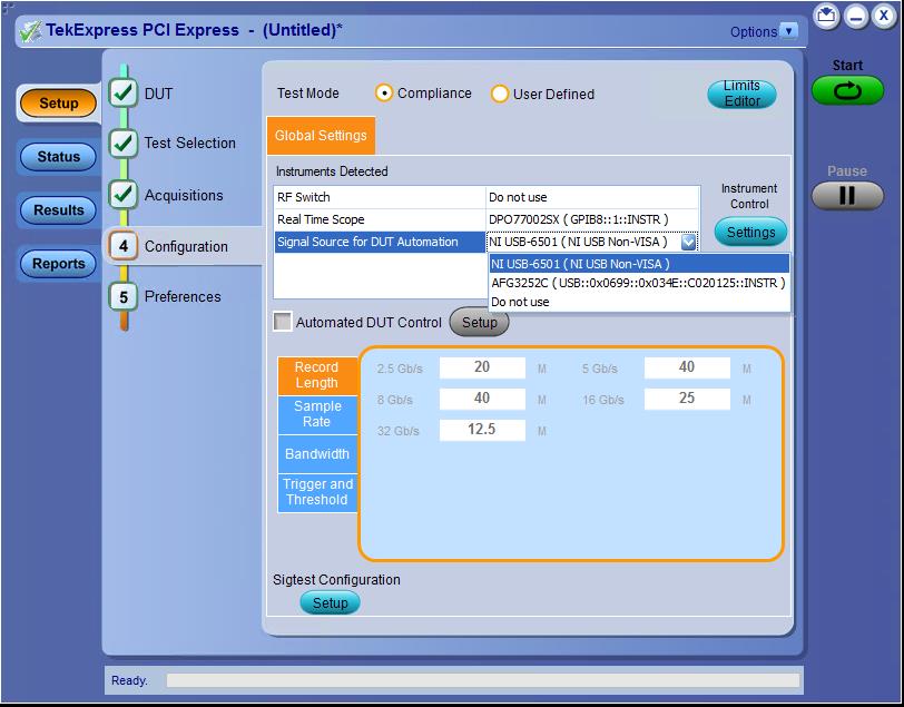
- In the Configuration section, click Global Settings.
- In the Instruments Detected section, click the drop-down arrow to the right of Real Time Scope and make sure that the oscilloscope with the (GPIB8::1::INSTR) designation is in the list.
See also
Search instruments connected to the application
| Note:The instruments required for the test setup must be connected and detected by the application, before running the test. |
- Select .
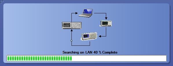
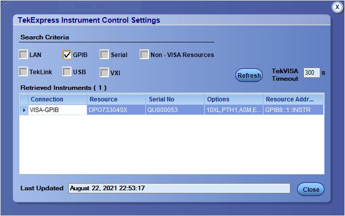
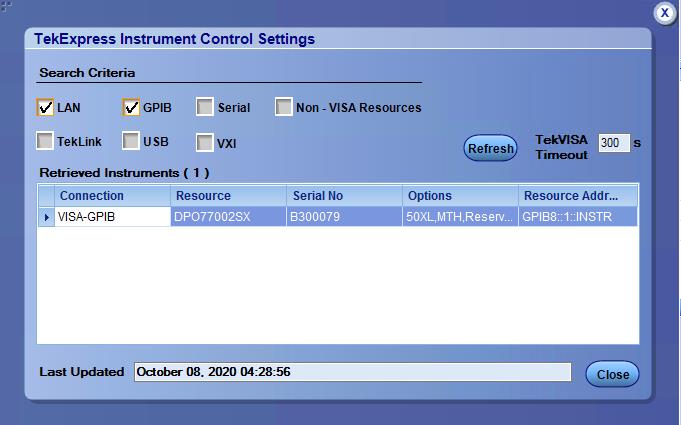
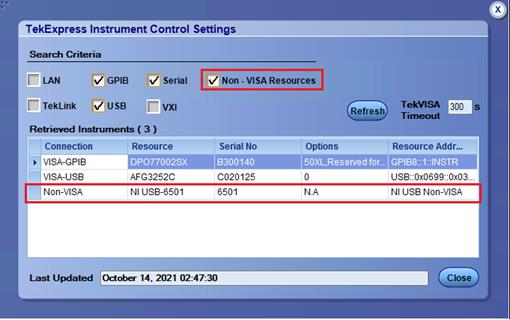
- In the Search Criteria section of the Instrument Control Settings dialog box, select the connection types of the instruments to search. Instrument search is based on the VISA layer, but different connections determine the resource type, such as LAN, GPIB, and USB. For example, if you choose LAN, the search will include all the instruments supported by the TekExpress that are communicating over the LAN.
- Click Refresh. The TekExpress application searches for the connected instruments. Search status of the instruments connected to LAN
- When the search is complete, a dialog box lists the instrument-related details based on the search criteria. For example, for the Search Criteria as GPIB, the application displays all the GPIB instruments connected to the application. TekExpress Instrument Control Settings window.
The details of the instruments are displayed in the Retrieved Instruments table. The time and date of instrument refresh is displayed in the Last Updated field.
Starting the application
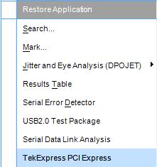
To start the TekExpress PCI Express, select from the oscilloscope menu bar. Applications > TekExpress PCI Express
During start, a "My TekExpress" folder is created in the Documents folder of the current user and gets mapped to "X" drive. When the application is closed properly, the "X" drive gets unmapped. Session files are then stored inside the X:\PCI Express folder. If this file is not found, the application runs an instrument discovery program to detect connected instruments before starting TekExpress PCI Express.
To keep the TekExpress PCI Express application on top of any application, select Keep On Top from the options menu. If the application goes behind the oscilloscope application, select Applications >TekExpress PCI Express to bring the application to the front.
Application controls
| Item | Description | ||
|---|---|---|---|
Options menu | Menu to display global application controls. | ||
Test panel | Controls that open tabs for configuring test settings and options. | ||
Start / Stop button  | Use the Start button to start the test run of the measurements in the selected order. If prior acquired measurements are not cleared, then new measurements are added to the existing set. The button toggles to the Stop mode while tests are running. Use the Stop button to abort the test. | ||
Pause / Continue button | Use the Pause button to pause the acquisition. When a test is paused, this button changes as Continue. | ||
| Clear button | Use the Clear button to clear all existing measurement results. Adding or deleting a measurement, or changing a configuration parameter of an existing measurement, also clears measurements. This is to prevent the accumulation of measurement statistics or sets of statistics that are not coherent. This button is available only on Results panel.
| ||
Application window move icon | Place the cursor over the top of the application window to move the application window to the desired location | ||
Minimize icon | Minimizes the application. | ||
Close icon | Close the application. | ||
Mini view / Normal view  | Mini view displays the run messages with
the time stamp, progress bar, Start / Stop button, and Pause /
Continue button. The application moves to mini view when you click
the Start button.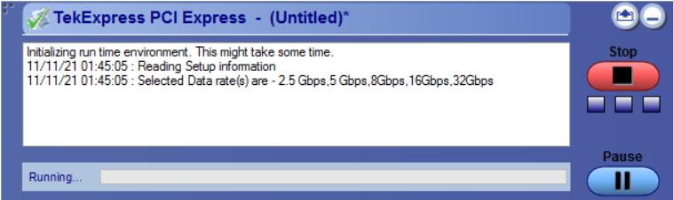 |
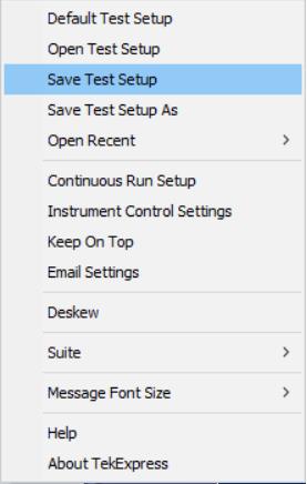
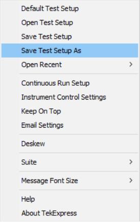
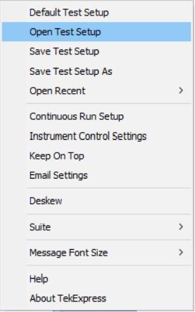
Options menu functions
To access the Options menu, click 
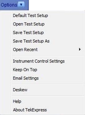
| Menu | Function |
|---|---|
| Default Test Setup | Opens a new test setup with default configurations. |
| Open Test Setup | Opens a previously saved test setup. Displays the list of previously saved test setup file names. Make the selection and click OK to open the test setup. |
| Save Test Setup | Saves the current test configurations with the specified file name. |
| Save Test Setup As | Saves the current test setup with a different file name or file type. |
| Open Recent | Displays the recently opened test setup file names. Make the selection and click OK to open the test setup. |
| Instrument Control Settings |
Detects, lists, and refreshes the connected instruments found on the specified connections (LAN, GPIB, USB, Serial, Non-VISA Resources, TekLink, and VXI). |
| Keep On Top |
Always keeps the TekExpress PCI Express application on top of all the applications. |
| Email Settings | Configures email options for test run and result notifications. |
| Deskew | Loads oscilloscope channel deskew settings into the application. |
| Help | Displays the TekExpress PCI Express help. |
| About TekExpress |
Displays the application name, version, and hyperlink to end the user license agreement. |
TekExpress instrument control settings
Use the TekExpress Instrument Control Settings dialog box to search the instruments (resources) connected to the application. You can use the Search Criteria options to search the connected instruments depending on the connection type. The details of the connected instrument is displayed in the Retrieved Instruments window.
To access, click Options > Instrument Control Settings. Select USB and LAN as search criteria for TekExpress application and click Refresh. The connected instruments displayed in the Retrieved Instruments window and can be selected for use under Global Settings in the test configuration section.
See also
Configure email settings
Use the Email Settings utility to get notified by email when a measurement completes or produces any error condition. Follow the steps to configure email settings:
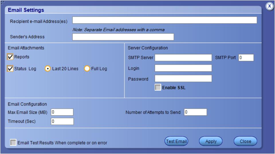
-
Select Options > Email Settings to open the Email Settings dialog box.
-
(Required) For Recipient email Address(es), enter one or more recipient email addresses. To include multiple addresses, separate the addresses with commas.
-
(Required) For Sender’s Address, enter the email address used by the instrument. This address consists of the instrument name, followed by an underscore, followed by the instrument serial number, then the @ symbol, and the email server ID. For example: [email protected].
-
(Required) In the Server Configuration section, type the SMTP Server address of the Mail server configured at the client location, and the SMTP Port number, in the corresponding fields.
If this server requires password authentication, enter a valid login name, password, and host name in the corresponding fields.
Note:If any of the above required fields are left blank, the settings will not be saved, and email notifications will not be sent. -
In the Email Attachments section, select from the following options:
-
Reports: Select to receive the test report with the notification email.
-
Status Log: Select to receive the test status log with the notification email. If you select this option, then also select whether you want to receive the full log or just the last 20 lines.
-
-
In the Email Configuration section:
-
Enter a maximum file size for the email message. Messages with attachments larger than this limit will not be sent. The default is 0 MB.
-
Enter the number in the Number of Attempts to Send field, to limit the number of attempts that the system makes to send a notification. The default is 1. You can also specify a timeout period.
-
-
Select the Email Test Results When complete or on error check box. Use this check box to quickly enable or disable email notifications.
-
To test your email settings, click Test Email.
-
To apply your settings, click Apply.
-
Click Close when finished.
Setup panel: Configure the test setup
The Setup panel contains sequentially ordered tabs that help you guide through the test setup and execution process.
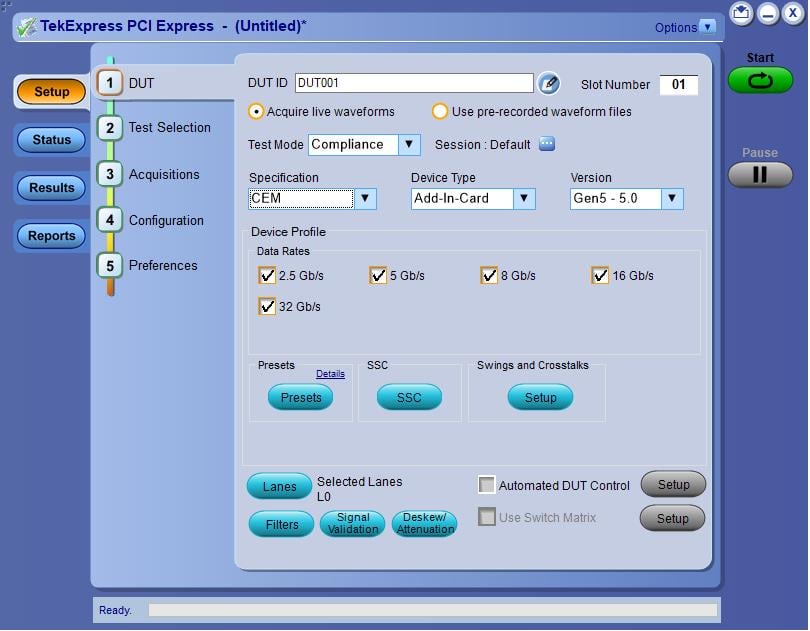
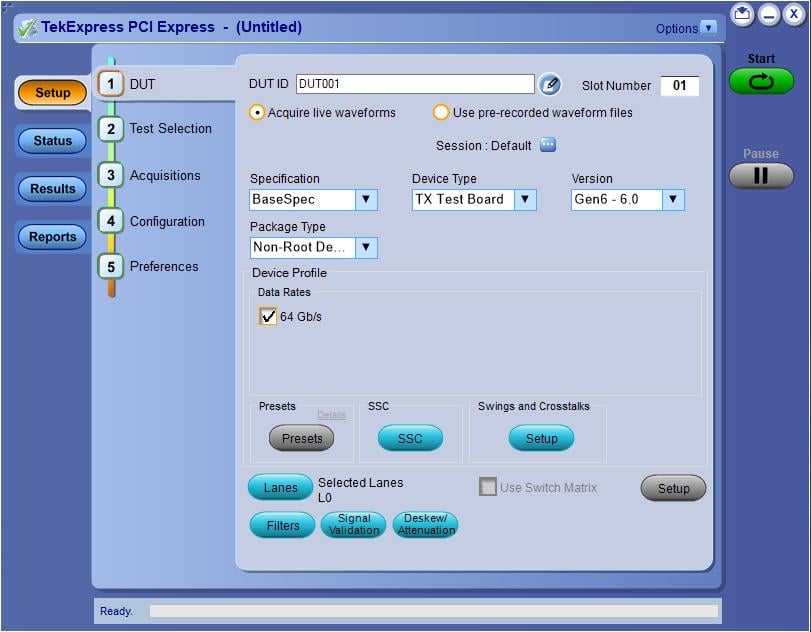
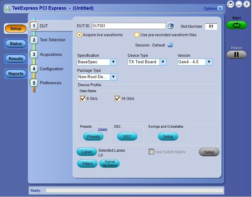
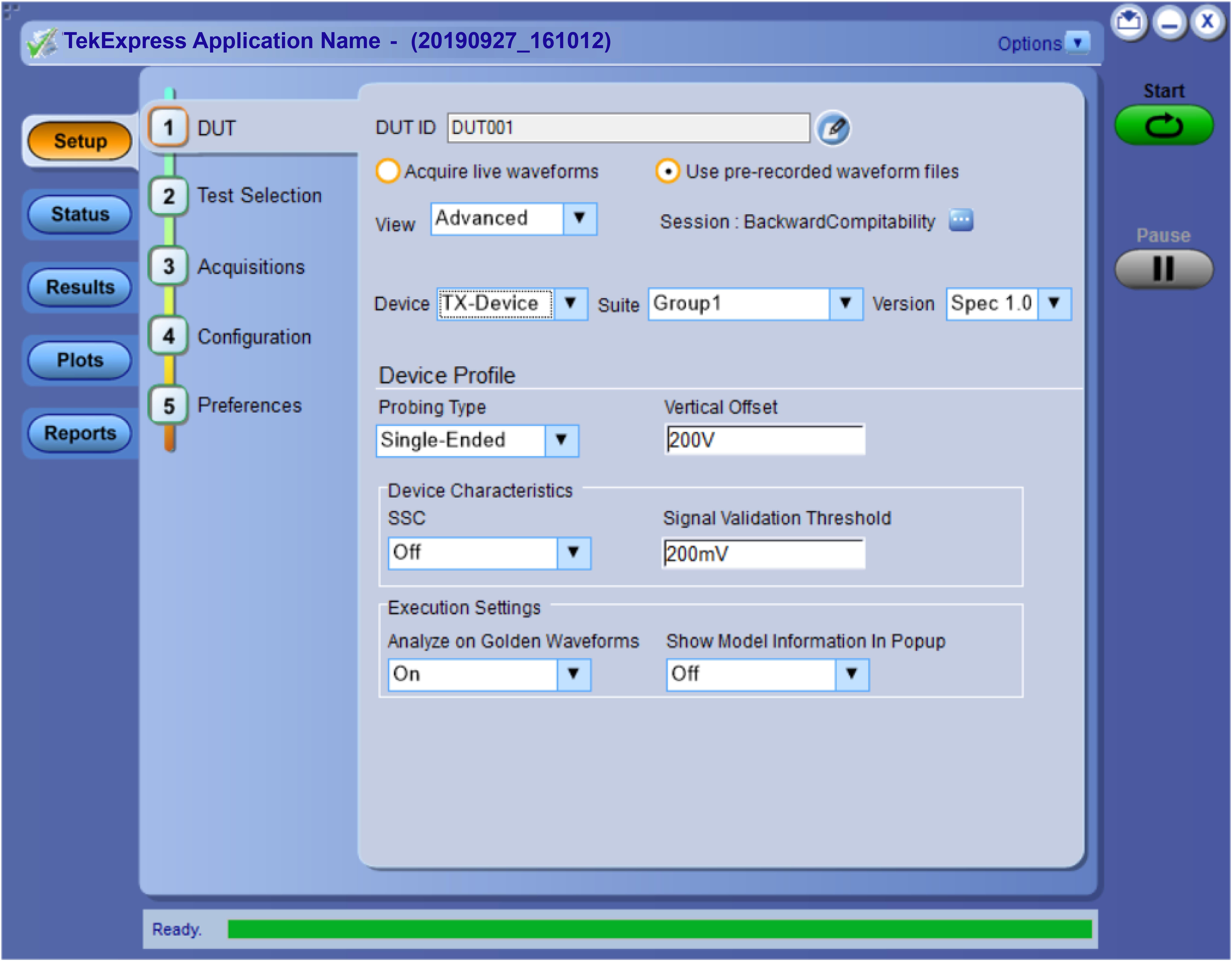
DUT: Set DUT settings
Use the DUT tab to select parameters for the device under test. These settings are global and apply to all tests of current session. DUT settings also affect the list of available tests in the Test Selection tab.
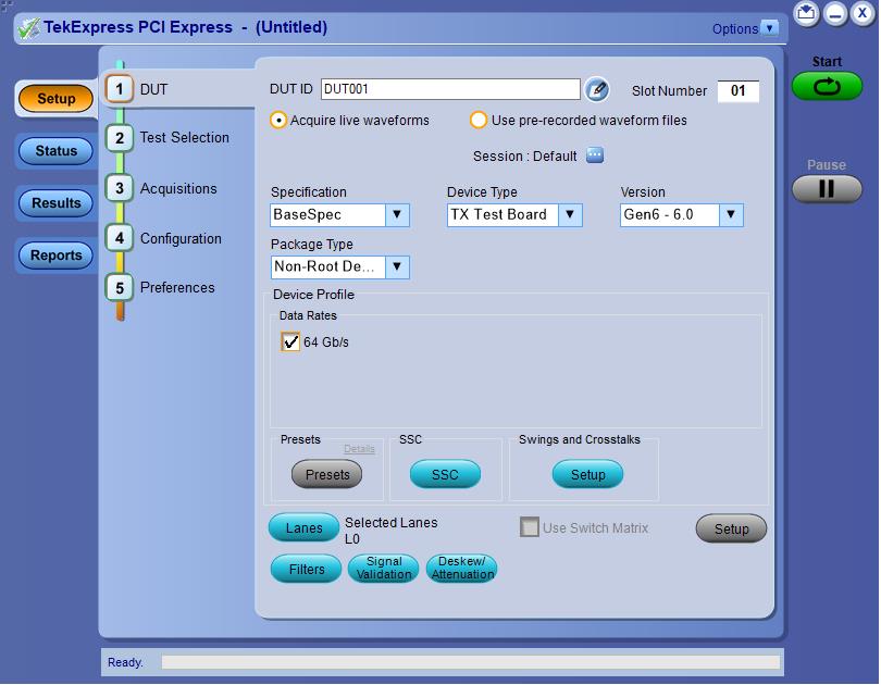
Click Setup > DUT to access the DUT parameters:
|
Setting |
Description | |||
|---|---|---|---|---|
| DUT ID | Adds an optional text label for the DUT to reports. The default value is DUT001. | |||
| Slot Number | The slot parameter (1, 2, 4, 8,16, or 32) of the DUT. | |||
 | Opens a Comments dialog box in which to enter optional text to add to a report. The maximum number of characters is 256. To enable or disable comments appearing on the test report, refer View a generated report. | |||
| Acquire live waveforms | Acquire active signals from the DUT for testing. | |||
| Use prerecorded waveform files | Run tests on a saved waveform. Load a saved test setup | |||
| Test Mode |
Sets the overall testing mode. Select Compliance or User Defined:
| |||
| Session | Allows you to save multiple config sessions and run multiple config/run sessions together. | |||
| Specification | PCIe supports the CEM, BaseSpec, RefClockSpec, U.2 (SFF-8639), and M.2 specification. | |||
| Device Type |
Sets the DUT device type. The device type available depends on the selected specification. Following are the device types for each specifications
| |||
| Version |
Sets the DUT generation version. Available versions are:
| |||
| Device Profile | ||||
| Data Rates | Sets the data rates to test (2.5 Gb/s, 5 Gb/s, 8 Gb/s, 16 Gb/s, 32 Gb/s, and 64 Gb/s). The data rates available depend on the selected DUT version. | |||
| Filters | Opens the Filter Setup dialog box to select custom filter files with which to perform link analysis on the source waveforms. | |||
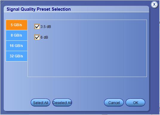
| Presets |
Opens the Presets dialog box. User can select Gen2 preemphasis and Gen3 to Gen5 presets(P0 to P10) for signal quality tests in respective tabs. All preemphasis and presets are selected by default. At least one preemphasis level/preset must be selected for each generation.
  | |||
| Swings and Crosstalks | Voltage Swing Limits |
Sets the lane/link transmitter p-p voltage swing. This affects the limits applied to certain measurements based on the settings and does not change anything on the DUT tab. | ||
| Crosstalk Limits |
Sets specific eye test limits depending on if the DUT design uses interleaved or non interleaved routing. This affects the limits applied to certain measurements based on the settings and does not change anything on the DUT tab. This is applicable for Gen2.
| |||
| SSC (Spread Spectrum Clocking) |
Enables or disables SSC clocking. This affects the limits applied to certain measurements based on the settings and does not change anything on the DUT tab. | |||
| Lanes |
Opens the Test Lane Setup dialog box to select the lanes to test. Lanes required for compliance testing are colored orange. At least one lane must be selected. The Link Width setting determines the number of lanes that can be tested. | |||
| Automated DUT Control |
Enables automatic toggling of the DUT into different test modes (generation/equalization). Requires the use of an AFG or AWG or NI USB toggle tool. Click Setup to access the Automated DUT control setup | |||
| Use Switch Matrix |
Select to use the switch matrix. This solution allows you to map each of the several transmitter signals and forward the selected input either to another relay or to the oscilloscope channel. Click Setup to configure the switch matrix. Refer Switch Matrix application for more details on configurations.
| |||
| Signal validation | Signal validation | Sets the application to validate acquisition signals and perform the specified action to take when acquired signals do not meet requirements. Select the action from the list. | ||
| Perform Pattern Decoding | Select to validate the pattern according to the respective lane and preset for Gen3. | |||
| Deskew/Attenuation |
Provides the option of setting deskew and attenuation values on the scope either in an automated way or manual way. Refer Deskew and Attenuation for more details. | |||
| Test Type |
Use this procedure to choose between CEM or Base type of Ref Clock testing.

| |||
Filter setup dialog box
The filter setup dialog box lets you select custom filter files for performing link analysis on the source waveforms. The options available depends on the Specification selected.
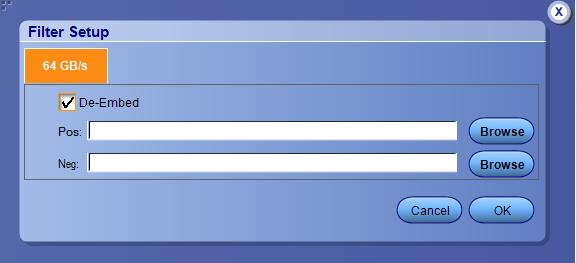
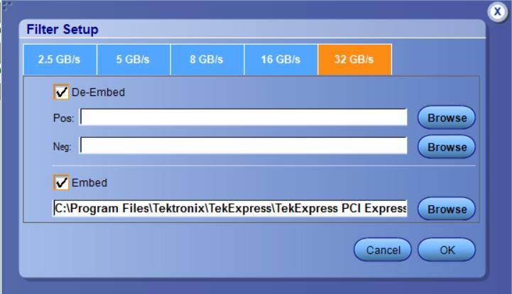
De-Embed
Select de-embed for the data rate; click Browse and select the de-embed filter file.
| Note:
|
Embed
Select Embed for the data rate; click Browse and select the embed filter file.
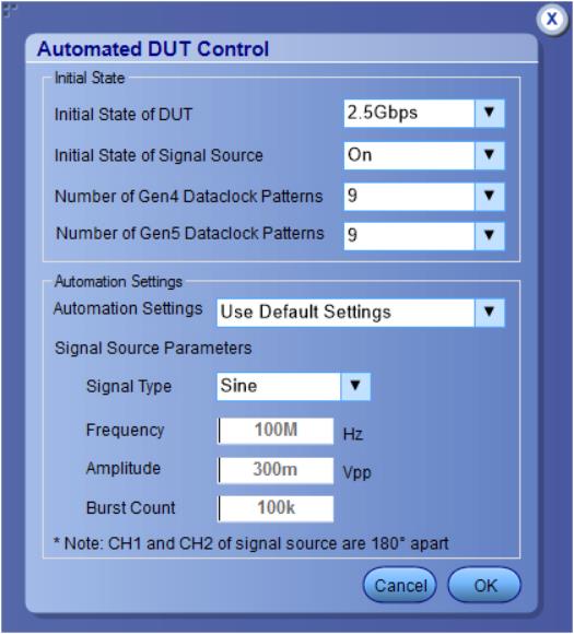
Automated DUT control setup
The Automated DUT Control dialog box sets the parameters needed for automatic toggling of the DUT into different test modes (generation/equalization). DUT automation requires the use of a signal source AFG or AWG or NI USB toggle.
| Parameter | Description | ||||
|---|---|---|---|---|---|
| Initial State | |||||
| Initial State of DUT | Sets the starting state of the DUT. | ||||
| Initial State of Signal Source | Sets the AFG/AWG state to On (default) or Off. The On state enables the AFG/AWG output before the application starts signal acquisition. Some DUTs will toggle to the next signal state when the AFG/AWG initial state is On. Set the initial state to Off for these types of DUTs before running automated tests. | ||||
| Number of Gen4 Dataclock patterns | Allows to select the number of Gen4 dataclock patterns the DUT supports, between 0 to 15.
| ||||
| Number of Gen5 Dataclock patterns | Allows to select the number of Gen5 dataclock patterns the DUT supports, between 0 to 15.
| ||||
| Automation Settings | |||||
| Automation Settings (for AFG only) | The Automation Settings values are as follows :
| ||||
| Signal Source Parameters | |||||
| Signal Type | Valid signal types are Sine and Square. | ||||
| Frequency | Sets the AFG to output the specified frequency and amplitude values. | ||||
| Amplitude | |||||
| Burst Count | Sets the AFG to output the specified signal burst count.
| ||||
NI USB 6501 DUT Controller Support
- TekExpress PCIe TX application added support for National Instrument USB-6501 CBB controller device in TekExpress PCIE Express TX application. This device can be used to toggle the DUT.
- In order to detect the hardware and access it, the user will have to install the NI-DAQMX v20.7.1 software package in the Tekscope.
- Go to Configuration Panel.
- Click on the Instrument Control Settings button.
- In the TekExpress Instrument Control Settings pop-up window, check Non-VISA Resources and then click the Refresh button.
- If the NI device is connected to the scope, it will be shown in the Retrieved Instruments.
- Close the pop-up window.
- The device now can be selected under Signal Source for DUT Automation.
Multiple-session run
Multiple-sessions run feature allows you to save multiple config sessions and run multiple config/run sessions together.

- Config session – Session saved by user manually from Run/Config Sessions window.
- Run session – Session created automatically after the test is executed.
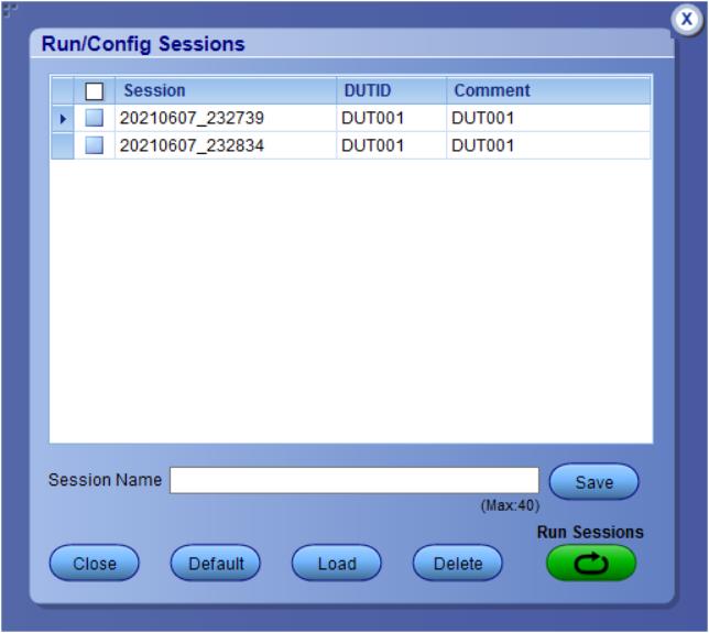
- Session Name: Enter the name to save the config session. The maximum number of character supported is 40 and special characters (.,..,...,\,/:?”<>|*) are not supported.
- Save: Save current configuration as a session with the given session name.
- Close: Close the Run/Config Session window.
- Default: Sets the application configurations to default values.
- Load: Load the selected config/run session.
- Delete: Delete the selected config/run session.
- Run Sessions: Run the selected config/run session.
Enable/ Disable the Multi Run session
By default the Multi Run Session is enabled in the application. Set the IsMultiSessionRunEnabled value to false to disable the Multi Run Session feature in the TekExpress.exe.Config file, which is downloaded along the application.
Test Selection: Select the tests
Use the Test Selection tab to select the tests. The test measurements available depends on the settings selected in the DUT tab.
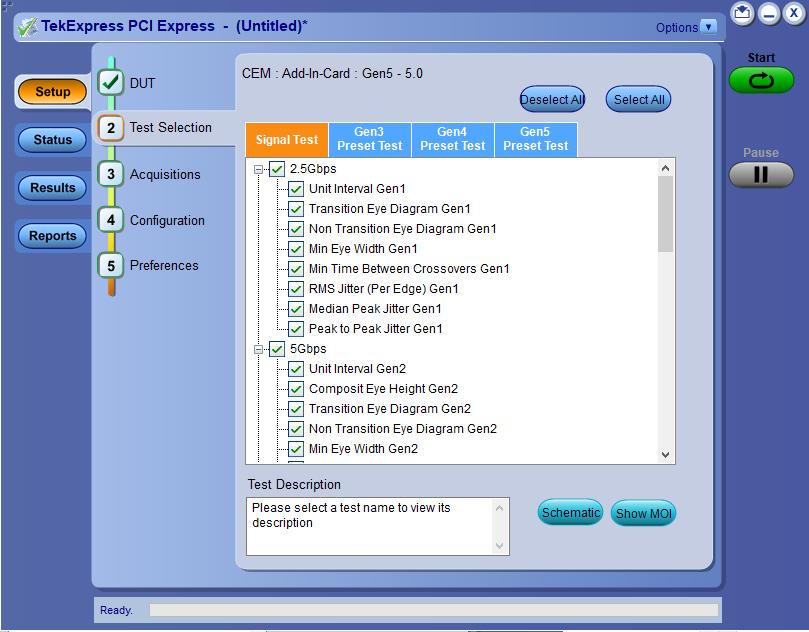
| Setting | Description |
|---|---|
| Signal Tests | Click + to expand a group of commands. Click the check box adjacent to a test group to select all tests in that group. Click check boxes adjacent to individual tests to select those tests. |
| Deselect All | Click Deselect All button to deselect all tests. |
| Select All | Click Select All button to select all tests. |
| Show MOI | Click Show MOI button to open the MOI (Methods of Implementation) document for all measurements. |
| Schematic | Click Schematic button to view a diagram that shows the correct DUT and equipment setup for the selected test. Use to verify your test equipment setup before running the test. |
| Gen3, Gen4, and Gen5 testing |
Click the required Preset Test tab and select the presets tests. |
| Lanes | Click the Lanes button in the Preset Test tab to view and select which lanes to use for preset testing. At least one lane must be selected. |
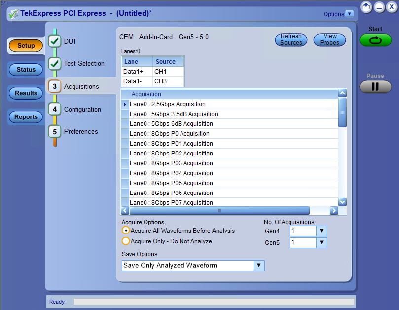
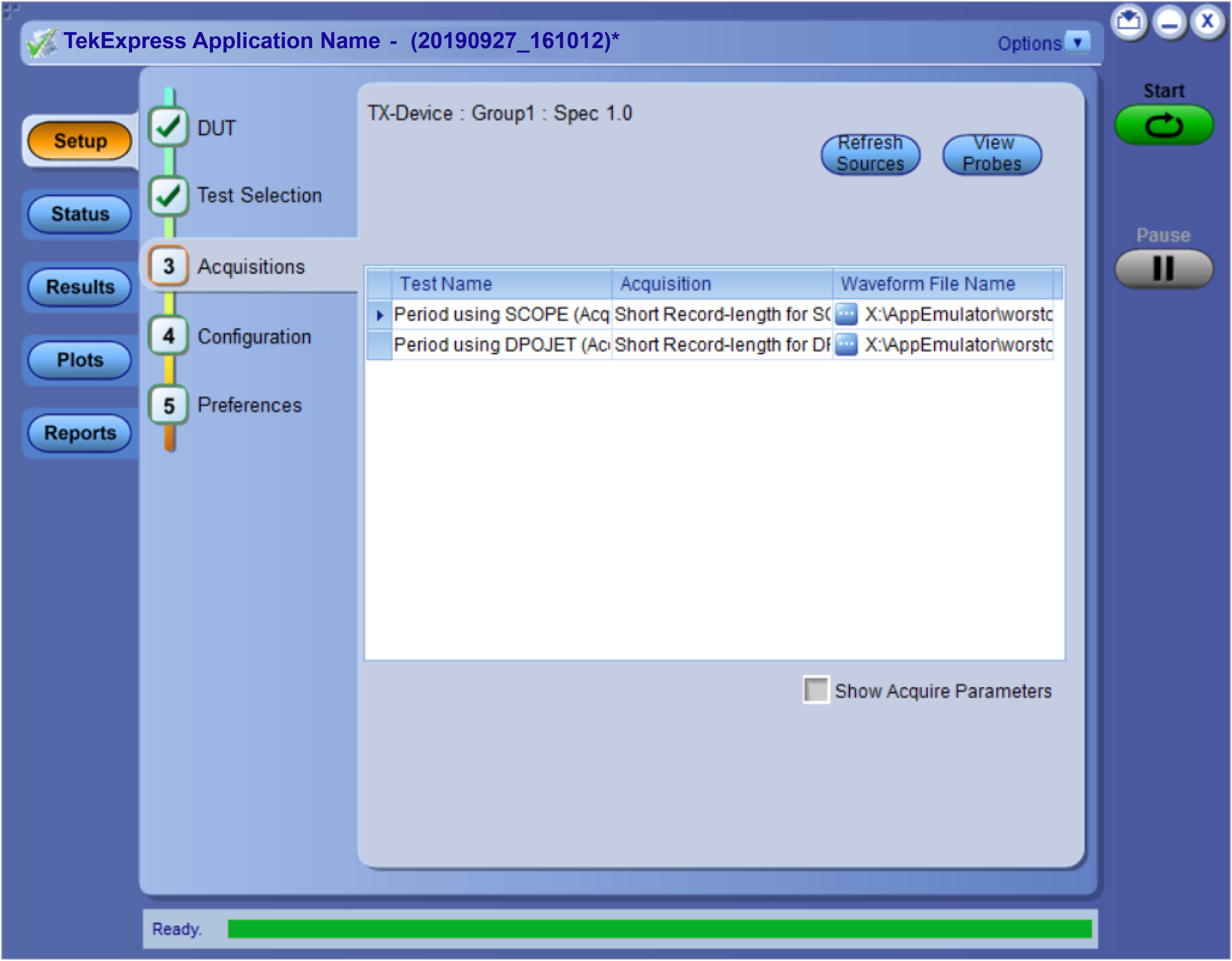
Acquisitions: Set waveform acquisition settings
Use the Acquisition tab in the Setup panel to view and select test acquisition parameters, including the signal source channels, acquisition options, and waveform save options. This panel also shows the signal inputs required for the selected DUT parameters.
Contents displayed on this tab depend on whether you acquire active waveforms or use prerecorded waveform files (as set in the DUT tab. Contents displayed on this tab also depend on detected probes and the specified DUT type.
Active waveforms
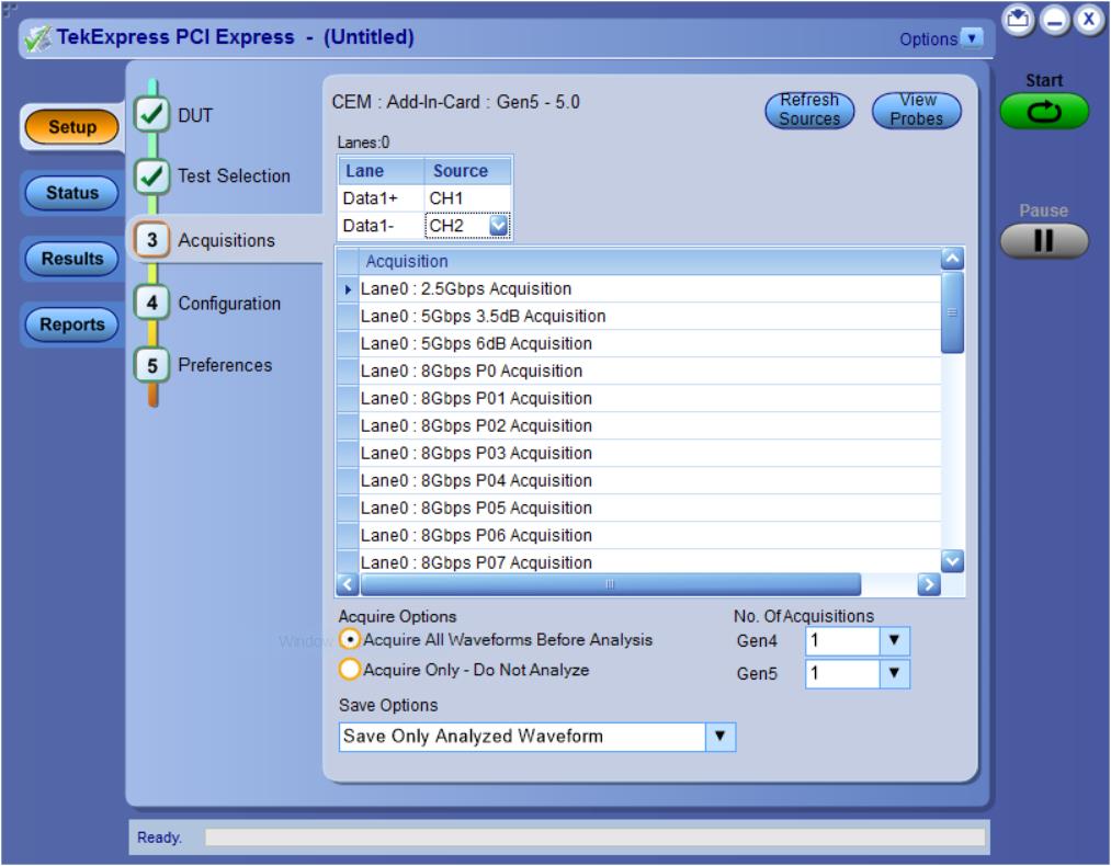
| Setting | Description | ||
|---|---|---|---|
| Source Selection | Click the Source fields to select signal sources for the listed lanes. The number of lanes shown depends on the parameters set in the DUT tab. | ||
| Refresh Sources | Click Refresh Sources to refresh the probe configuration after changing any probes. (This button performs the same function as the Refresh button in the Probe Configuration dialog box.) | ||
| View Probes | Click View Probes to view the detected probe configuration. Use the View Probes dialog box to enable or disable probe signal source access in the application.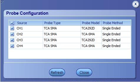
| ||
| Acquire Options | Click the Acquire Options controls to set how the application acquires and analyzes signals. | ||
| Save Options | Click the Save Options field to set how the application saves acquired waveforms (save all waveforms, save all waveforms after applying filters, or discard all waveforms after running analysis). | ||
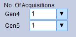
| No. of Acquisitions | Select the No. of acquisition for Gen4 from the drop-down. |
Prerecorded waveforms
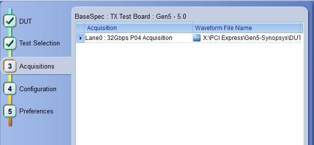
When using prerecorded waveform files, this panel lists available prerecorded waveform files. You can only select the source of the prerecorded waveform file for each test. See Set acquisition waveform source for prerecorded waveform files.
Set acquisition options
Select an Acquire Option to set the order in which waveforms are acquired and analyzed:
- Acquire All Waveforms Before Analysis: Acquire all waveforms required by tests before performing analysis. All required user interventions (such as connecting to different lanes) are completed, and waveforms acquired, before the analysis is run. You can turn off the DUT after the acquisitions are completed.
- Acquire Only – Do Not Analyze: Acquire all waveforms required by tests, and then stop (do not use waveforms to perform test analysis). Use this setting for testing multiple DUTs once the test and application settings are correct. Acquire all required waveforms and save the session for each DUT, and then recall the waveforms at a later point to analyze in Prerecorded mode.
See also
Set acquisition waveform save options
Select a Save Option to set how to save acquired test waveforms:
- Save All the Waveforms: Save all waveforms that were acquired for tests.
- Save Only Analyzed Wfms: Save waveforms that was used for analysis.
- No Waveforms Saved – Discard after analysis: Delete all acquired waveform data after analysis is complete.
Waveforms are saved to a folder that is unique to each session (a session starts when you click the Start button). The folder path is
X:\PCI Express\Untitled Session\<DUT ID>\<date>_<time>. Images created for each analysis, CSV files with result values, reports, and other information specific to that particular execution are also saved in this folder. When the session is saved, content is moved to that session folder and the “Untitled Session” gets replaced by the session name.
Waveform file names
This application uses file name conventions to access the waveforms. It is recommended to save the waveforms with following file names.
-
Differential data waveform: Tek_PCIe_Slot_DataRate_LaneNumber_PresetNumber_Data_Differential.wfm
Example: Tek_PCIe_01_8Gbps_Ln00_P0_d_Diff.wfm
-
Differential clock waveform: Tek_PCIe_Slot_DataRate_LaneNumberClk_PresetNumber_Data_Differential.wfm
Example: Tek_PCIe_01_8Gbps_Ln00Clk_P0_d_Diff.wfm
-
Single ended data positive waveform: Tek_PCIe_Slot_DataRate_LaneNumber_PresetNumber_Data_Pos.wfm
Example: Tek_PCIe_01_8Gbps_Ln00_P0_d_Pos.wfm
-
Single ended data negative waveform: Tek_PCIe_Slot_DataRate_LaneNumber_PresetNumber_Data_Neg.wfm
Example: Tek_PCIe_01_8Gbps_Ln00_P0_d_Neg.wfm
See also
Set acquisitions signal source
Set acquisition waveform source for prerecorded waveform files
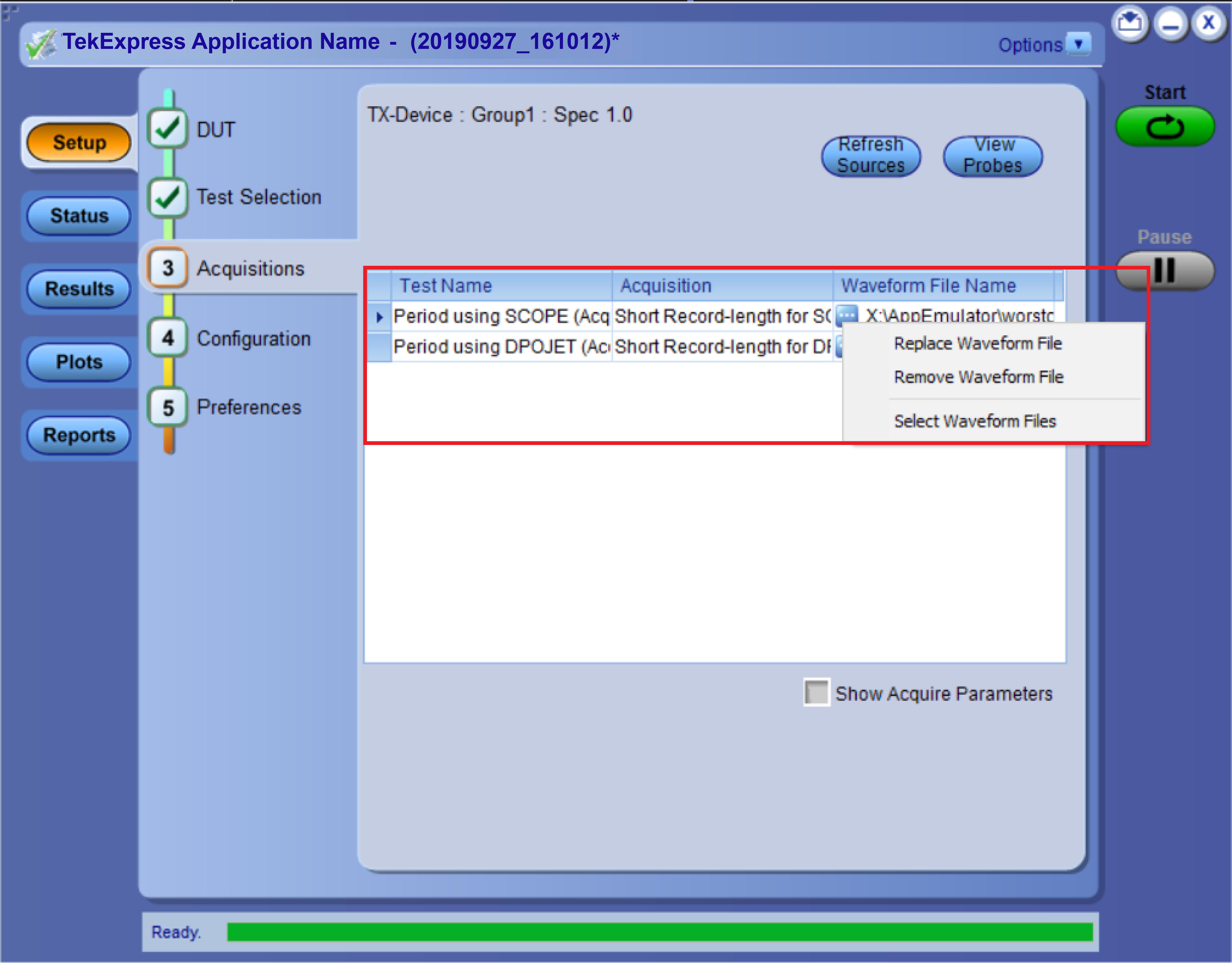
Set acquisition waveform source for prerecorded waveform files
When using prerecorded waveform files, there are no acquisition source selections to make. You can only select the source of the prerecorded waveform files for each test.
If you selected to use a prerecorded waveform file (in the DUT tab), the lane and source fields are not applicable and are not shown. The Acquisition tab instead shows a table of the waveforms used for the required test acquisitions.
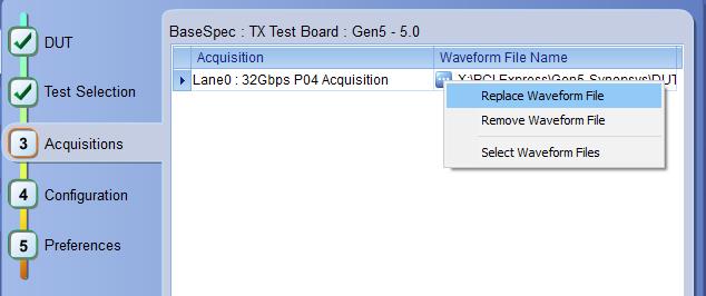
You can load a different waveform file for each table item. To load a different waveform file:
- Click the ellipsis button (
- Select the waveform task to perform (replace, remove, or select the waveform file).
- Use the dialog box to navigate to and select the waveform file with which to replace the current file. You need to select all required differential waveforms for analysis. For example, select one data waveform and one clock waveform for each acquisition (except 2.5 Gbps) for testing a system board.

| Note:Clock signals are not required for Gen1 (2.5 Gbps data rate) testing.
|
See also
Set acquisition signal source
Use this procedure to set the channel sources for live waveform acquisitions. The number of Lane and Source fields shown depends on the number of lanes selected for testing in the DUT tab.
- Click Setup > Acquisitions.
- Click in the Source column of the field to change.
- Click the arrow button to list available sources from which to select.
See also
Set acquisition waveform save options
Set acquisition waveform source for prerecorded waveform files
No. of Acquisitions
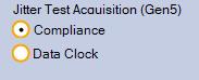
Jitter Test Acquisition
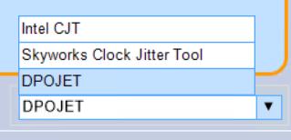
Analysis Tool
Use this procedure to choose the analysis tool to be used for the Ref Clock testing.
- Intel CJT
- Skyworks Clock Jitter Tool
- DPOJET
Configuration: Set measurement limits for tests
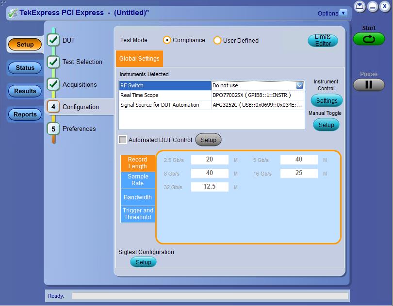
Use Configuration tab to view and configure the Global Settings and the measurement configurations. The measurement specific configurations available in this tab depends on the selections made in the DUT panel and Test Selection panel.
| Settings | Description |
|---|---|
| Mode |
Determines whether test parameters are in compliance or can be edited.
|
| Limit Editor |
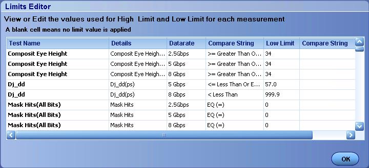
Displays the upper and lower limits for the applicable measurement using different types of comparisons. In the Compliance Mode, you can view the measurement high and low limits used for the tests displayed in the tree view of the Measurements tab. When running tests in User Defined Mode, you can edit the limit settings in the Limits Editor. The second table shows the tests with the limits calculated dynamically as per the specification.
|
| Setting | Description | ||
|---|---|---|---|
| Test Mode | Determines whether test parameters are in compliance or can be edited (User Defined Mode).
| ||
| Instruments Detected | Displays a list of the connected instruments found during the instrument discovery. Instrument types include equipment such as oscilloscopes and signal generators. | ||
| Instrument Control | Click Settings to search for connected instruments and view instrument connection details. Connected instruments displayed in TekExpress instrument control settings and can be selected for use under Global Settings in the test configuration section. | ||
| Manual Toggle |
Click Setup to manually toggle AWG or AFG. This is enabled when the Signal Source for DUT Automation in Instruments Detected is selected. | ||
| Automated DUT Control | Enables automatic toggling of test patterns for DUT tests. Requires an AWG or AFG as part of the test setup. Click Setup to configure the DUT automation settings. | ||
| Record Length, Sample Rate, Bandwidth |
These settings apply to all tests selected for the indicated data rate.
| ||
| Sig Validation Threshold | Sets the threshold voltage to use for signal validation. | ||
| Trigger Type (Gen3/Gen4/Gen5) |
| ||
| CTLE | This configuration setting allows the user to configure for CTLE optimization for Gen6 jitter measurements. Refer CTLE optimization feature for more details. | ||
| Scope Noise | This configuration setting allows the user to apply scope noise compensation for CTLE optimization and measurement analysis for Gen6 data rate test. Refer Scope Noise Characterization for more details. | ||
| SigTest Configuration |
Click Setup; select the executable (.exe) for Gen1, 2, 3, 4, and 5 and template configuration for signal quality and preset tests for the data rates selected. Check/Un-check Silent mode to run sigtest in Silent mode/non-silent mode. | ||
| Analysis tool (For RfClockSpec Only) |
|
CTLE optimization feature
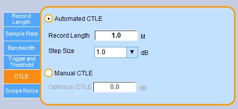
- Record Length:
- The Record Length of the waveform to be acquired for CTLE optimization.
- Range 1M to 20M. Default value is 1M
- Step Size:
- Sets up the step size for the CTLE optimization iteration.
- Values: 1, 0.5, 0.25
- Optimum CTLE:
- User defined CTLE value.
- Default value 0.0 dB
Scope Noise Characterization
Automated Scope Noise calculates the Scope Noise for various Vertical settings, Filter files, and CTLE. During execution it will select the Scope Noise which is closest in Vertical Scale to the Vertical Scale decided. Manual Mode will use the same Noise Compensation irrespective of Vertical Scale and CTLE applied. Use the radio buttons to switch between these modes. It will calculate the scope noise value for the selected scales and for different Filter combinations. For example: Live_BT, Live_BT_CTLE0, Live_BT_CTLE1…. Live_BT_CTLE15, and store them in a csv file. The file path is C:\Program Files\Tektronix\TekExpress\TekExpress PCI Express\ScopeNoiseData.
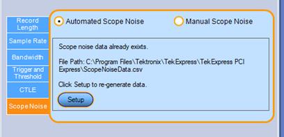
Automated Scope Noise
Manual Scope Noise
Preferences: Set the test run preferences
Use Preferences tab to set the application action on completion of a measurement. The Preferences tab has the feature to enable or disable certain options related to the measurement execution.
Refer the below table for the options available in the Preferences tab:
| Setting | Description |
|---|---|
| Execution Options | |
| Show alert when new deskew values are configured on TekScope | |
| Actions on Test Measurement Failure | |
| On Test Failure, pause the test and let me investigate | Select to pause the test run and allow you to investigate when the test execution is failed. |
| On Test Failure, stop and notify me of the failure |
Select to stop the test run on Test Failure, and to get notified via email. By default, it is unselected. Click Email Settings to configure the email settings to receive notifications. |
| Popup Settings | |
| Auto close Warnings and informations during Sequencing Auto close after <no> seconds | Select to close the warnings and information window automatically after the specified amount of time. Specify the time in seconds using the edit box. |
| Auto close Error Messages during Sequencing. Show in Reports Auto close after <no> seconds | Select to close the error message window automatically after the specified amount of time. Specify the time in seconds using the edit box. |
Status panel: View the test execution status
The Status panel contains the Test Status and Log View tabs, which provides status on the test acquisition and analysis (Test Status) and listing of test tasks performed (Log View tab). The application opens the Test Status tab when you start to execute the test. Select the Test Status or the Log View tab to view these items while the test execution is in progress.
View test execution status
The tests are grouped and displayed based on the Clock and Data lane. It displays the tests along with the acquisition type, acquire, and analysis status of the tests. In pre-recorded mode, Acquire Status is not valid.
The Test Status tab presents a collapsible table with information about each test as it is running. Use the symbols to expand (

| Control | Description |
|---|---|
| Test Name | Displays the measurement name. |
| Acquisition | Describes the type of data being acquired. |
| Acquire Status | Displays the progress state of the acquisition:
|
| Analysis Status | Displays the progress state of the analysis:
|
View test execution logs
The Test Status tab displays the detailed execution status of the tests. Also, displays each and every execution step in detail with its timestamp information. The log details can be used to troubleshoot and resolve any issue/bug which is blocking the test execution process.
| Control | Description |
|---|---|
| Message History | Lists all the executed test operations and timestamp information. |
| Auto Scroll |
Enables automatic scrolling of the log view as information is added to the log during the test execution. |
| Clear Log | Clears all the messages from the log view. |
| Save |
Saves the log file into a text file format. Use the standard Save File window to navigate to and specify the folder and file name to save the log text. |
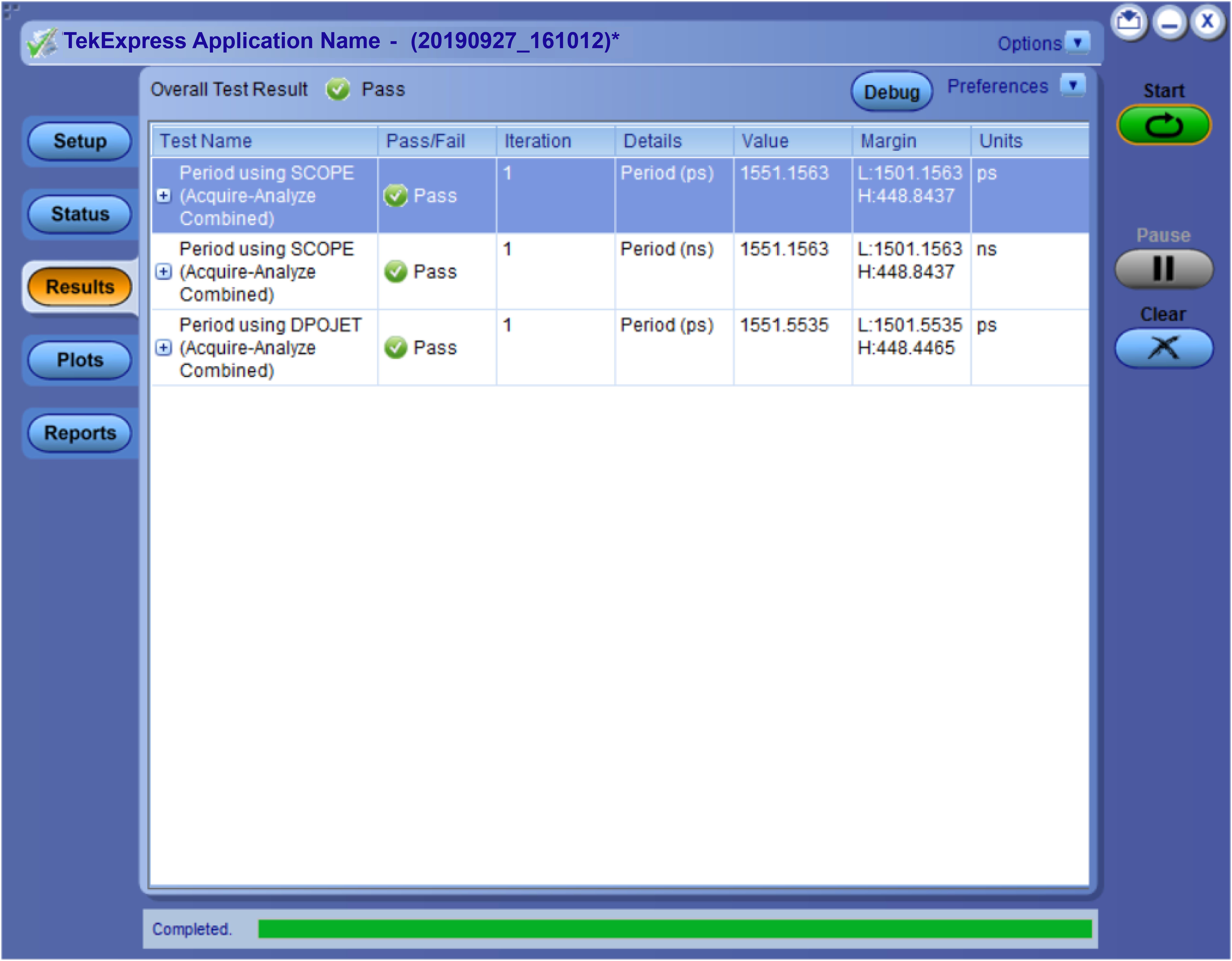
Results panel: View summary of test results
When a test execution is complete, the application automatically opens the Results panel to display a summary of test results.
In the Results table, each test result occupies a row. By default, results are displayed in summary format with the measurement details collapsed and with the Pass/Fail column visible.
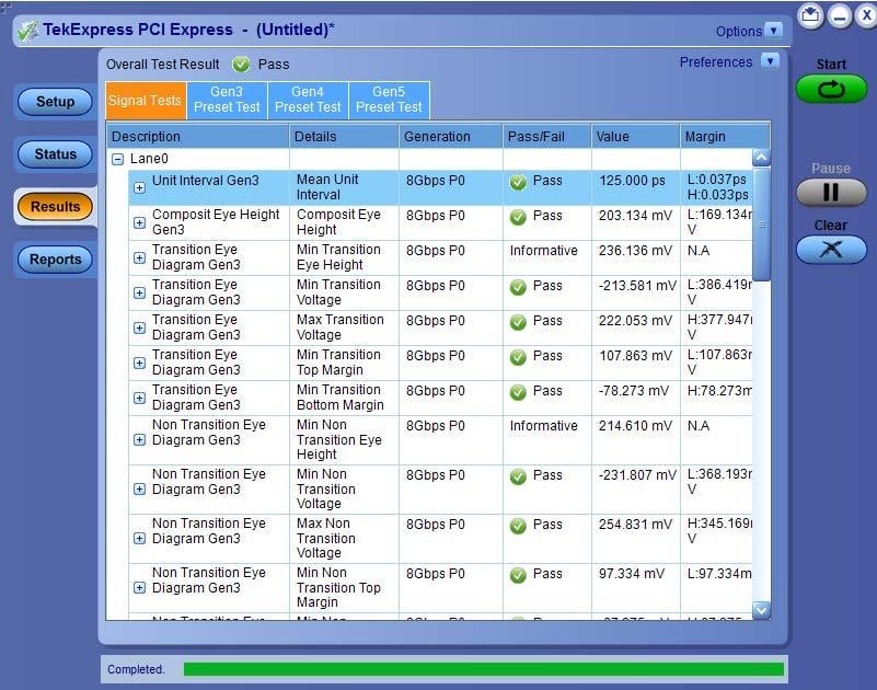
Click ![]() icon on each measurement in the row to expand and to display the minimum and maximum parameter values of the measurement.
icon on each measurement in the row to expand and to display the minimum and maximum parameter values of the measurement.
Filter the test results
- To remove or restore the Pass/Fail column, select .
- To collapse all expanded tests, select .
- To expand all the listed tests, select View Results Details from the Preferences menu in the upper right corner.
- To enable or disable the wordwrap feature, select .
- To view the results grouped by lane or test, select the corresponding item from the Preferences menu.
- To expand the width of a column, place the cursor over the vertical line that separates the column from the column to the right. When the cursor changes to a double-ended arrow, hold down the mouse button and drag the column to the desired width.
- To clear all test results displayed, click Clear.
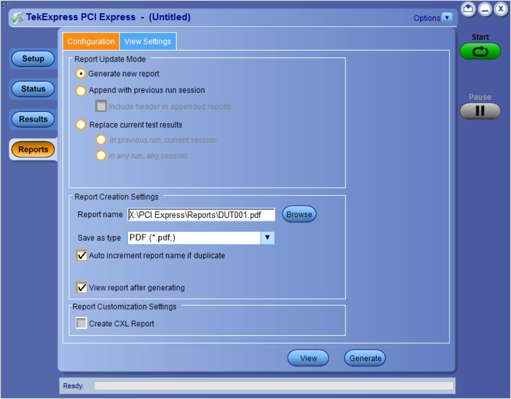
Reports panel: Configure report generation settings
Click Reports panel to configure the report generation settings and select the test result information to include in the report. You can use the Reports panel to configure report generation settings, select test content to include in reports, generate the report, view the report, browse for reports, name and save reports, and select report viewing options.
Report configuration settings
The Configuration tab describes the report generation settings to configure the Reports panel. Select report settings before running a test or when creating and saving test setups. Report settings configured are included in saved test setups.
| Control | Description | ||
|---|---|---|---|
| View | Click to view the most current report. | ||
| Generate | Generates a new report based on the current analysis results. | ||
| Report Update Mode Settings | |||
| Generate new report | Each time when you click Run and when the test execution is complete, it will create a new report. The report can be in either .mht, .pdf, or .csv file formats. | ||
| Append with previous run session | Appends the latest test results to the end of the current test results report. Each time when you click this option and run the tests, it will run the previously failed tests and replace the failed test result with the new pass test result in the same report. | ||
| Include header in appended reports | Select to include header in appended reports. | ||
| Replace current test results | Replaces the previous test results with the latest test results. Results from newly added tests are appended to the end of the report. | ||
| In previous run, current session |
Select to replace current test results in the report with the test result(s) of previous run in the current session. | ||
| In any run, any session | Select to replace current test results in the report with the test result(s) in the selected run session’s report. Click and select test result of any other run session. | ||
| Report Creation Settings | |||
| Report name |
Displays the name and path of the <Application Name> report. The default location is at To change the report name or location, do one of the following:
Be sure to include the entire folder path, the file name, and the file extension. For example:
Open an existing report Click Browse, locate and select the report file and then click View at the bottom of the panel. | ||
| Save as type |
Saves a report in the specified file type, selected from the drop-down list. The report is saved in .csv, .pdf, or .mht.
| ||
| Auto increment report name if duplicate |
Sets the application to automatically increment the name of the report file if the application finds a file with the same name as the one being generated. For example: DUT001, DUT002, DUT003. This option is enabled by default. | ||
| View report after generating |
Automatically opens the report in a Web browser when the test execution is complete. This option is selected by default. | ||
| Report Customization Settings | |||
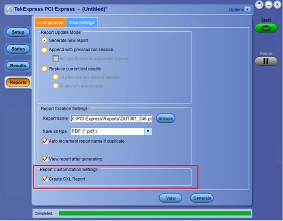
| Create CXL Report |
Creates CXL device type for AIC/SYB of CEM Spec and Tx Test Board/SRIS Test Board of BaseSpec.
| ||
CXL Support
| Note:CXL device type support is newly added to the TekExpress PCIe TX application. |
- Supported Device Type and Data Rates:
Device Types Data Rates CXL Add-In Card - 8 GB/s
- 16 GB/s
- 32 GB/s
CXL System Board - 8 GB/s
- 16 GB/s
- 32 GB/s
CXL TX Test Board - 8 GB/s
- 16 GB/s
- 32 GB/s
CXL SRIS TX Test Board - 16 GB/s
- 32 GB/s
- Specification Reference: PCI Express Card Electromechanical Specification Revision 4.0 v1.0 and PCI Express Base Specification Revision 4.0 v1.0
- Test Setup: The test setup for CXL is same as CEM or Base specification device types. Additionally, user needs to select Create CXL Report checkbox in the report panel to run the test in CXL mode.
Configure report view settings
The View Settings tab describes the report view settings to configure the Reports panel. Select report view settings before running a test or when creating and saving test setups. Report settings configured are included in saved test setups.
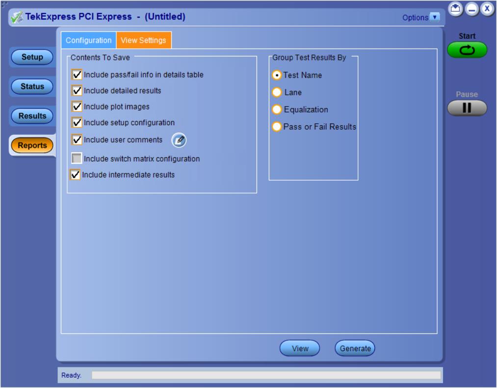
| Control | Description |
|---|---|
| Contents To Save Settings | |
| Include pass/fail info in details table | Select to include pass/fail information in the details table of the report. |
| Include detailed results | Select to include detailed results in the report. |
| Include plot images | Select to include the plot images in the report. |
| Include setup configuration | Sets the application to include hardware and software information in the summary box at the top of the report. Information includes: the oscilloscope model and serial number, the oscilloscope firmware version, and software versions for applications used in the measurements. |
| Include user comments | Select to include any comments about the test that you or another user have added in the DUT tab of the Setup panel. Comments appear in the Comments section, below the summary box at the beginning of each report. |
| Include switch matrix configuration | Select to include the switch matrix configuration in the report. |
| Include Intermediate Results | Select to include intermediate test results for Gen4 and Gen5. |
| Group Test Result By | |
| Test Name | Select to group the test results based on the test name in the report.. |
| Lane | Select to display the test results by lane. |
| Equalization | Select to display the test results by equalization. |
| Pass/Fail Results | Select to display the test results by pass or fail results. |
View a generated report
Sample report and its contents
A report shows detailed results and plots, as set in the Reports panel.
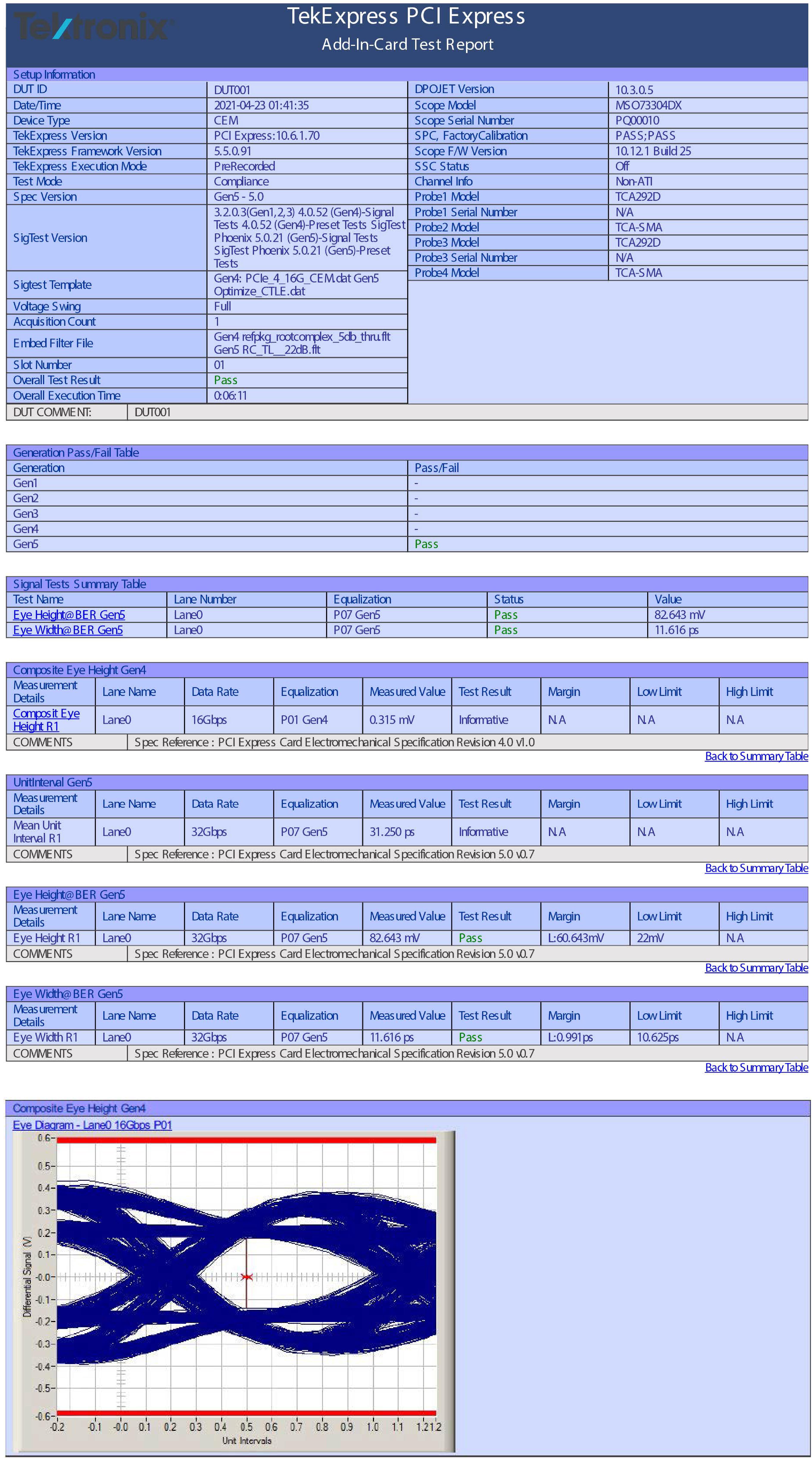
- Setup Information
- The summary box at the beginning of the report lists setup configuration information. This information includes the oscilloscope model and serial number, optical module model and serial number, and software version numbers of all associated applications.
- Test Name Summary Table
- The test summary table lists all the tests which are executed with its result status.
- Measurement
- The measurement table displays the measurement related details with its parameter value.
- User comments
-
If you had selected to include comments in the test report, any comments you added in the DUT tab are shown at the top of the report.
- Generation Pass/Fail Table
- The Generation Pass/Fail Table shows the pass/fail result of each individual generation. This table is shown only when the results are grouped by Test Name.
Saving and recalling test setup
Overview
You can save the test setup and recall it later for further analysis. Saved setup includes the selected oscilloscope, general parameters, acquisition parameters, measurement limits, waveforms (if applicable), and other configuration settings. The setup files are saved under the setup name at X:\TekExpress PCI Express
- Recall a saved configuration.
- Run a new session or acquire live waveforms.
- Create a new test setup using an existing one.
- View all the information associated with a saved test, including the log file, the history of the test status as it executed, and the results summary.
- Run a saved test using saved waveforms.
| Note:Images that are shown in this Saving and recalling test setup chapter are for illustration purpose only and it may vary depending on the TekExpress application. |
Save the configured test setup
You can save a test setup before or after running a test. You can create a test setup from already created test setup or using a default test setup. When you save a setup, all the parameters, measurement limits, waveform files (if applicable), test selections, and other configuration settings are saved under the setup name. When you select the default test setup, the parameters are set to the application’s default value.
- Select Options > Save Test Setup to save the opened setup.
- Select Options
> Save Test Setup As to save the setup with different name.
Load a saved test setup
To open (load) a saved test setup, do the following:
- Select Options
> Open Test Setup.
- From the File Open menu, select the setup file name from the list and click Open.
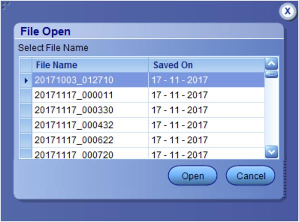
| Note:Parameters that are set for the respective test setup will enable after opening the file. |
Perform a test using pre-run session files
- Select Options
> Open Test Setup.
- From the File Open menu, select a setup from the list and then click Open.Note:Parameters that are set for the respective test setup will enable after opening the file.
- Switch the mode to Use Pre-recorded waveform files in the DUT panel.
- Select the required waveforms from the selected setup in the Acquisitions tab and click Start.
- The selected waveform file can be removed/replaced by clicking on the (
- After successful completion of the test, the waveform report files are stored at
X:\<Application Name>\Reports. - The overall test result status after completion of the test execution is displayed in the Results Panel.


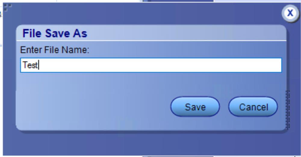
Save the test setup with a different name
- Select Options
> Save Test Setup As.
- Enter the new test setup name and click Save.
Switch Matrix application
Product description
Switch Matrix application allows to configure and setup automated multi-lane testing using RF switch. The solution allows you to map each of the several transmitter signals and forward the selected input either to another relay or to the oscilloscope channel.
Application overview
This section describes the Switch Matrix application settings.
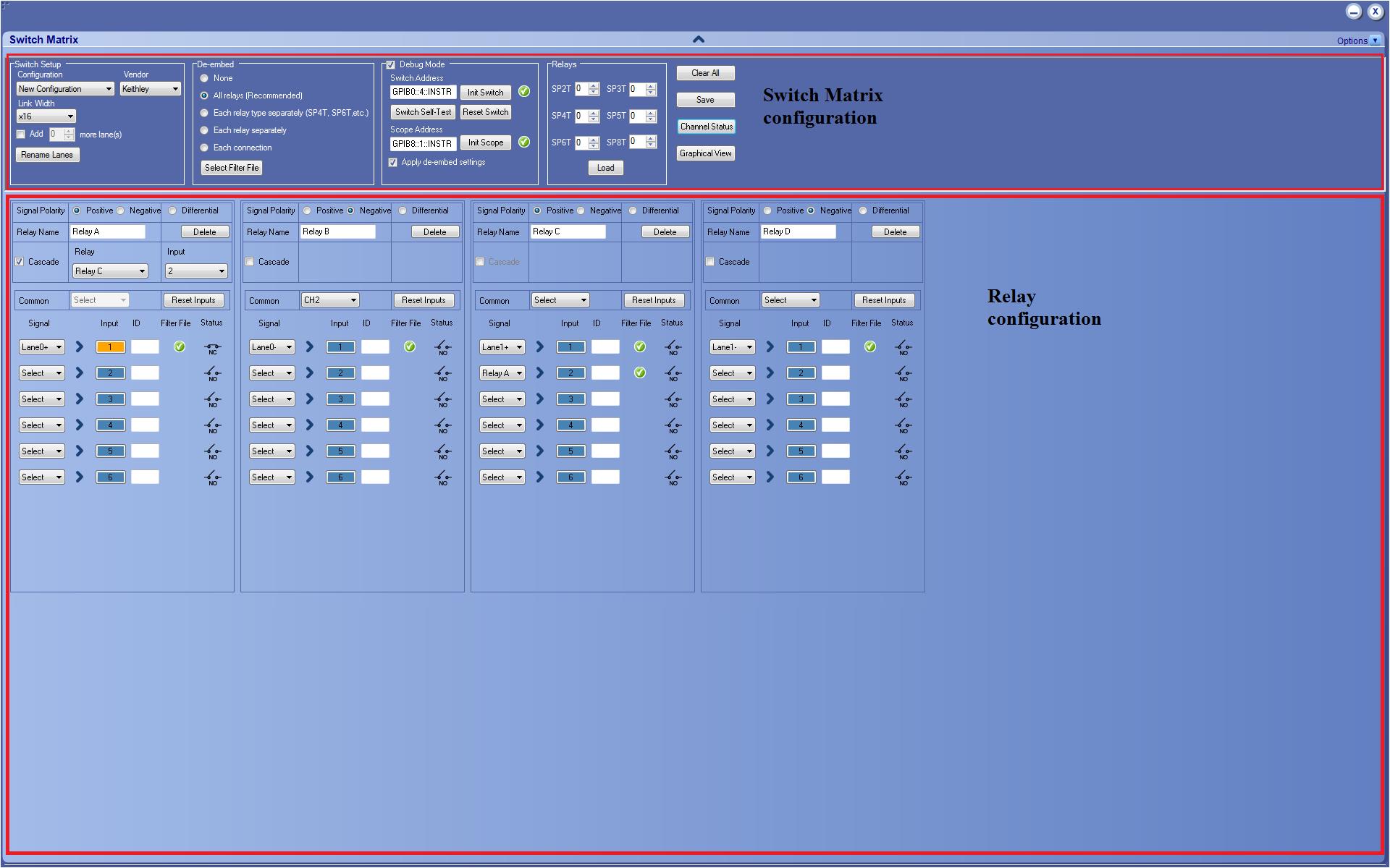
| Item | Description | ||||
|---|---|---|---|---|---|
 | Click to expand/collapse the switch matrix configuration. | ||||
|
Options 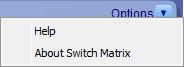 | Click Help to view the software help document and About Switch Matrix for software version. | ||||
| Switch Matrix configuration | |||||
|
Configuration 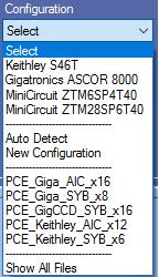 |
Select the configuration option:
| ||||
|
Vendor 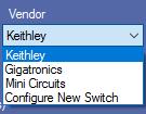 |
Select the vendor from the drop-down list. This field is displayed:
| ||||
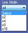 | Select the Link Width from the drop-down list. This determines the maximum number of lanes supported by the DUT. | ||||
|
Add <X> more lane(s)  |
Select to add extra lanes (Additional1, Additional2,....) to the lanes list. The extra lanes added are displayed in the relay signals. You can add a maximum of 10 lanes. | ||||
|
Rename Lanes  |
Click to rename the lanes. Enter the LanePrefix and select the increment label type to suffix by either number or alphabet. The number of lanes depends on the Link Width selected. Clear the Auto rename lane check box to set unique names for the lanes. 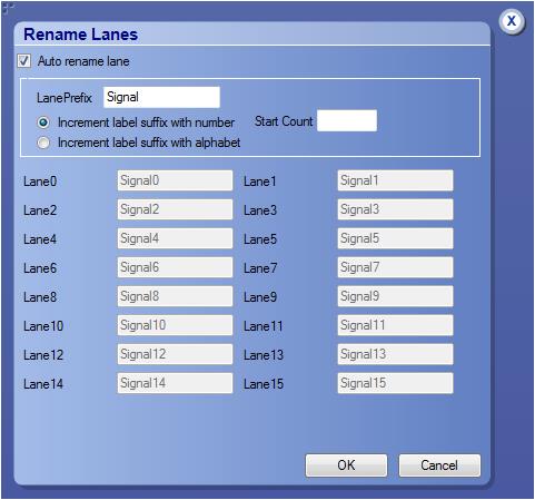 | ||||
| De-embed | |||||
|
De-embed 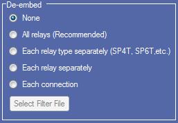 |
Select the De-embed option:
Select the de-embed option and click Select Filter File to browse and select the filter file(s). | ||||
| Debug Mode | |||||
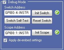 |
Select Debug Mode to manually configure the switch. Switch Address Enter the Switch Address in the GPIB or TCPIP format. GPIB format: TCPIP format: Init Switch This will synchronize the configuration of relay(s) in the application with the relay(s) in the switch. Synchronization will be successful only for the relays whose configuration matches with the physical switch. Pass/Fail status is displayed next to the button.
Switch Self-Test This will close and open all switch channels one-by-one and displays the pass/fail status of the channel next to the ID. A self-test report (CSV) is generated at the end of the process. You cannot abort this process.
Reset Switch Click Reset Switch to reset the switch. This will open all channels. Scope Address Enter the oscilloscope address in the GPIB or TCPIP format. GPIB format: TCPIP format: Init Scope Enter the oscilloscope address in the Scope Address field and click Init Scope to initialize the oscilloscope. This will establish the connection with the oscilloscope. The pass/fail status is displayed next to the button. Apply De-embed settings Select to apply de-embed settings to the channels. When the oscilloscope is initialized and de-embed settings are configured, closing a connection will apply the de-embed settings and then close the connection. | ||||
| Relays | |||||
|
Relays 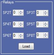 |
Select the relay(s). In SPnT, n represents the number of connection signals for the relay. For example, SP4T is a four signal connection relay. This field displays only for a new configuration. By default, zero relays are selected. Enter the total number of relays to be loaded in their respective input box and click Load. You can also click
| ||||
|
Save  |
Click to save the configuration at C:\ProgramData\Tektronix\Switch Matrix Configurations\*.xml. This operation checks whether all the required configurations are done. If any of the required configurations are not selected, then error popup is displayed, which prompts you to complete the configuration(s). | ||||
|
Clear All  |
Click to clear all configurations. The application will be loaded with Configuration drop-down (default). | ||||
|
Channel Status  |
Click to view the relays and status of channels of Keithley or Gigatronics switch. This updates the channel status dynamically. In Switch Channel Status Viewer, select the Vendor type, enter the Switch Address and click Init to initialize the switch. This will establish the connection with the switch. Click Query Status to get the details of the relays of the switch and the status of the channels. Click Reset to reset the status viewer. 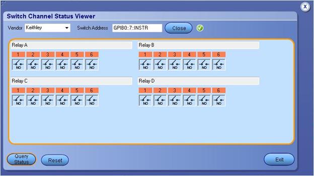 | ||||
|
Graphical View  |
Click to view the graphical representation of the configured relays. If the relays are cascaded, then they are also displayed in the graphical representation. | ||||
| Relay configuration | |||||
|
Signal Polarity  |
Select the signal polarity of DUT:
| ||||
|
Relay Name
 | Enter the relay name. This name should match the relay name of the connected switch. | ||||
|
Delete  | Click to delete the relay. This configuration is only available for the configured (loaded) relays, when Configuration > New Configuration is selected. | ||||
|
Cascade 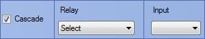 |
Select to cascade the relay by connecting the common channel as the input signal for another relay. Select the Relay and the Input of the relay. Check that the selected relay signal displays the appropriate relay name. The cascade settings is also displayed in the graphical view. Click here to get details about Cascade.
| ||||
|
Common
 |
Select the oscilloscope channel for Common. If cascaded, it displays the name of the relay. Click Reset Inputs to clear all connection signal settings.
| ||||
 |
Signal Select the DUT connection signal. This drop-down list shows the lanes based on Link Width and Signal Polarity settings. If the link width is x8 and signal polarity is Positive, then the Signal drop-down list will have Lane0+ to Lane7+ options. Input This button is enabled only in debug mode and if a valid signal is configured for the channel. Click to close or open the channel. ID Enter the three character alias name for the channel. This is shown in the graphical view of switch matrix configuration. Filter File This column shows
Status This column displays the status of the channel. Channel closed (normally closed) :
Channel opened (normally opened) :
| ||||


File name extensions
This application uses the following file name extensions:
| File name extension | Description |
|---|---|
| .html | Saved configuration and Graphical view file formats |
| .xml | Switch Matrix configuration files |
Status indicators
| Status indicators | Description |
|---|---|
 |
Success indicator |
 |
Failure indicator |
 |
Closed channel indicator (NC = Normally Closed) |
 |
Opened channel indicator (NO = Normally Opened) |
Saved configurations
Click to view the list of all saved files.
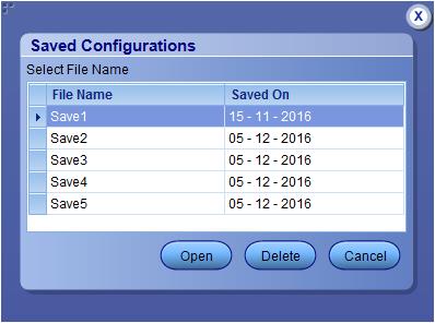
| Item | Description |
|---|---|
| Open | Opens the selected file. |
| Delete | Deletes the selected file. |
| Cancel | Closes the Saved Configurations window. |
De-embed settings
De-embed allows you to apply filter file(s) for relay(s). Select the De-embed option and click Select Filter File to browse and select the filter file(s).
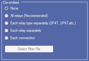
Graphical view of switch matrix configuration
The Graphical view displays the pictorial representation of the switch configuration.
The following figure displays the graphical view of a Keithley switch configuration.
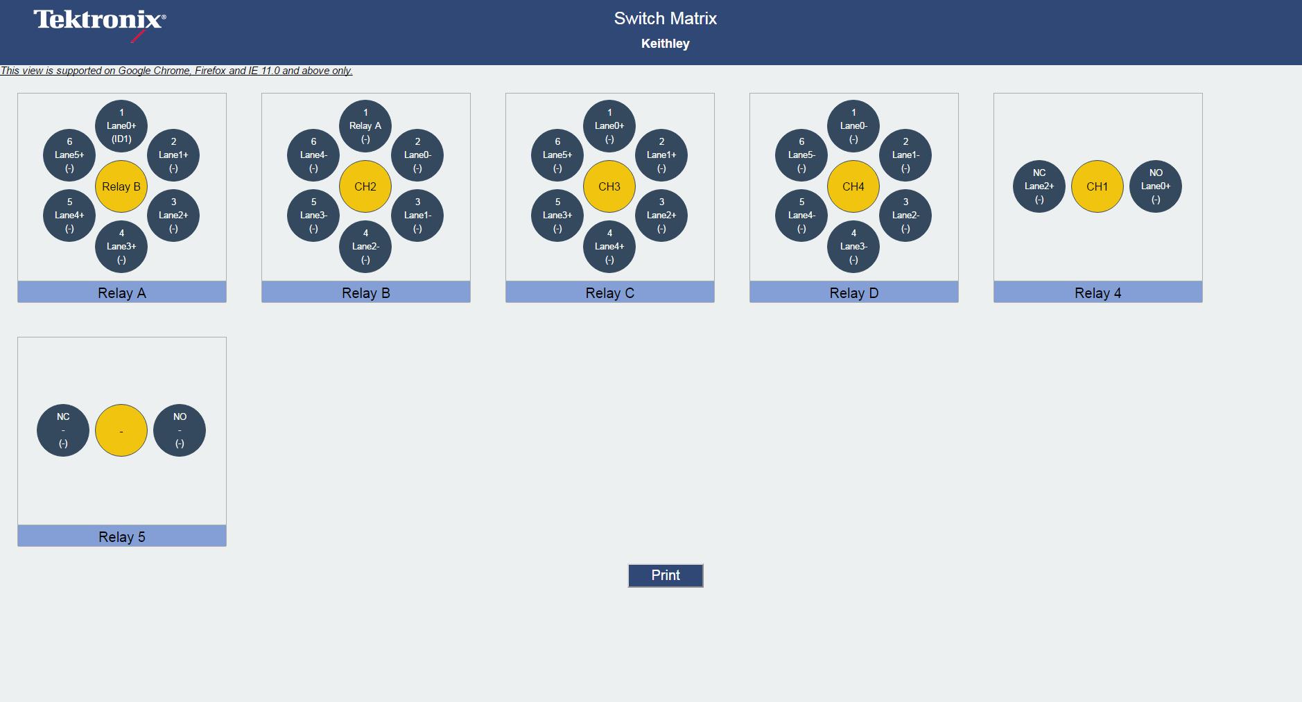
Saving the configuration
Click Save in the configuration panel; in the Configuration Save dialog box, enter the file name and click Save. The default save path is C:\ProgramData\Tektronix\Switch Matrix Configurations\.
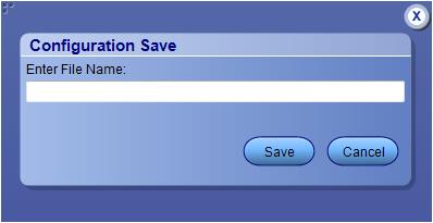
| Note:Save configuration checks whether all the required configurations are done. If any of the required configurations are not selected, then error message is displayed, which prompts you to complete the configuration(s).
|
Feature description
Error messages
| Error message | Possible solution |
|---|---|
|
"A filename cannot be empty and it cannot contain any of the following characters:\n\t. .. \\ / : ? \" < > | * ! @ # $ % ^ & * ( ) - + ., / \\ \' < > Also, the file name cannot be \"Keithley S46T\",\"Gigatronics ASCOR 8000\",\"MiniCircuit ZTM6SP4T40\",\"MiniCircuit ZTM28SP6T40\", \"Select\", \"New Configuration\", \"Custom\" , \"Auto Detect\" or \"Show All Files\"" | |
| Configure appropriate signals before the de-embed settings. | Select at least one signal for a relay before configuring the de-embed settings. |
| Either the instrument address is invalid or instrument is not connected. | Check the GPIB connection from oscilloscope to switch and verify the instrument address. |
|
Error occurred while trying to recall the configuration settings. Try re-creating configuration or recalling a different configuration file. | Re-create the configuration file or recall a different configuration file. |
| Error occurred while trying to access the connection for open/close operation. | |
| Filter file <FilterFileName> not found. | Reselect the de-embed filter file and try again. |
| Graphical view is not generated or does not exist. | |
| Initialize the switch | Initialize the switch and then perform the switch operations. |
| Instrument address doesn't belong to any supported switch. | Verify the switch address. |
| Instrument address is empty. | Instrument address cannot be empty. Enter a valid instrument address in the GPIB (GPIB0:X:INSTR) or TCPIP (TCPIP::IPADDR::INSTR) format. |
| No switch detected. Connect a Keithley or Mini Circuit switch and try auto detection by selecting Configuration > Auto Detect. | Check the GPIB connection from the oscilloscope to switch and whether the instrument is detected in TekVisa. |
| Number of relays cannot be more than 26 | |
| Please ensure that the name(s) of the configured relay(s) match the ones present on the physical switch. | |
| Relay name cannot be empty | |
| Scope initialization failed. Check if the address is valid and ensure that the instrument is switched on and try again. | Validate the oscilloscope address try again. |
| Switch communication failed... | Ensure that the switch is on. Reset the switch and try again. |
| Switch initialization failed. Check if the address is valid and ensure that the instrument is switched on and try again. | Validate the switch address and ensure that the instrument is switched on. Try again. |
| The start count cannot be more than 74 | |
| Timeout Error. Either the command is invalid or instrument is not active. | Check the command syntax and the connection of the instrument by SWITCH:*IDN command. |
| Two or more lanes have same name. The lane names should be unique. | |
| Two or more relays have same name. |
SCPI Commands
About SCPI command
| Note:If you are using an external PC to execute the remote interface commands, then install TekVISA in the PC to make the configurations. |
Socket configuration for SCPI commands
This section describes the steps to configure the TCPIP socket configuration in your script execution device and the steps to configure the TekVISA configuration in the oscilloscope to execute the SCPI commands.
TCPIP socket configuration
- Click .
-
In Windows Firewall with Advanced Security menu, select and click New Rule…
- In New Inbound Rule Wizard menu
- Select Port and click Next.
- Select TCP as rule apply, enter 5000 for Specific local ports and click Next.
- Select Allow the connection and click Next.
- Select Domain, Private, Public checkbox and click Next.
- Enter Name, Description (optional), and click Finish.
- Select Port and click Next.
- Check whether the Rule name is displayed in .
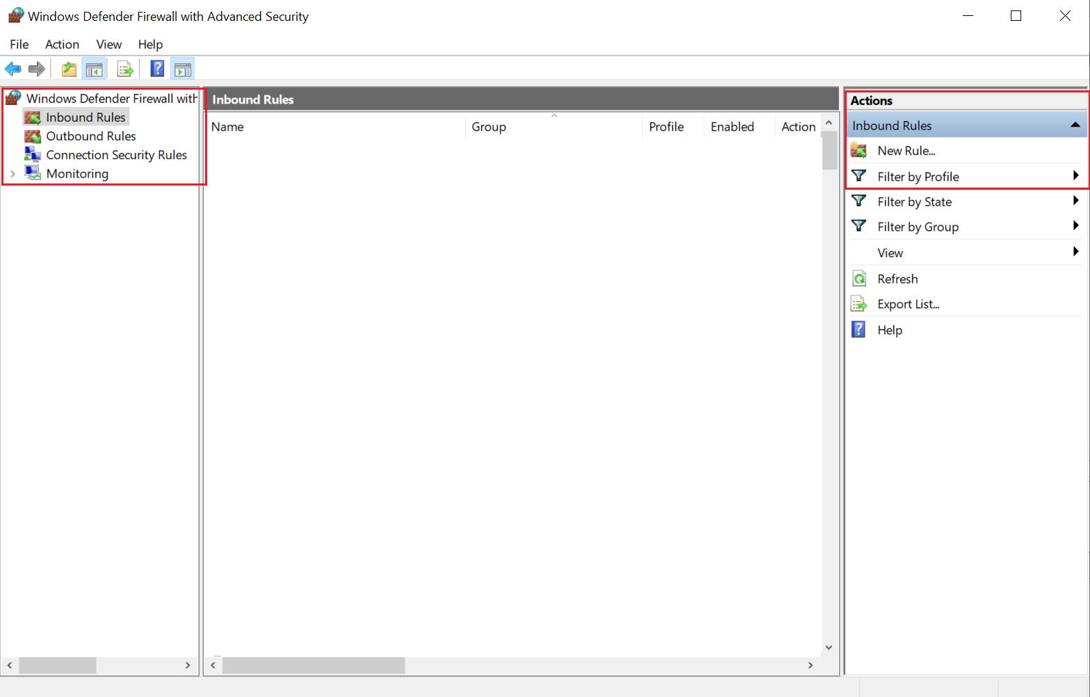
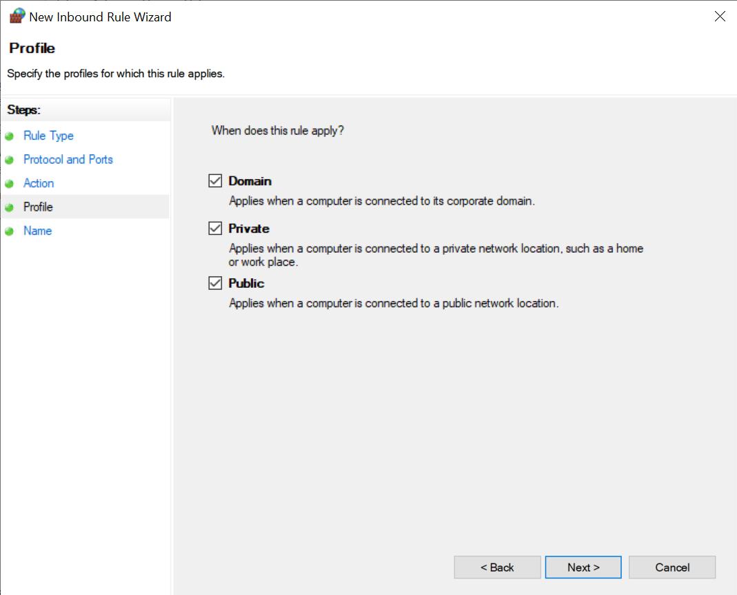
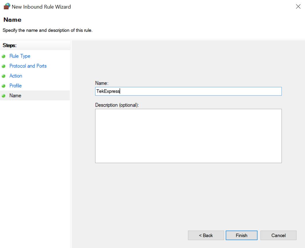
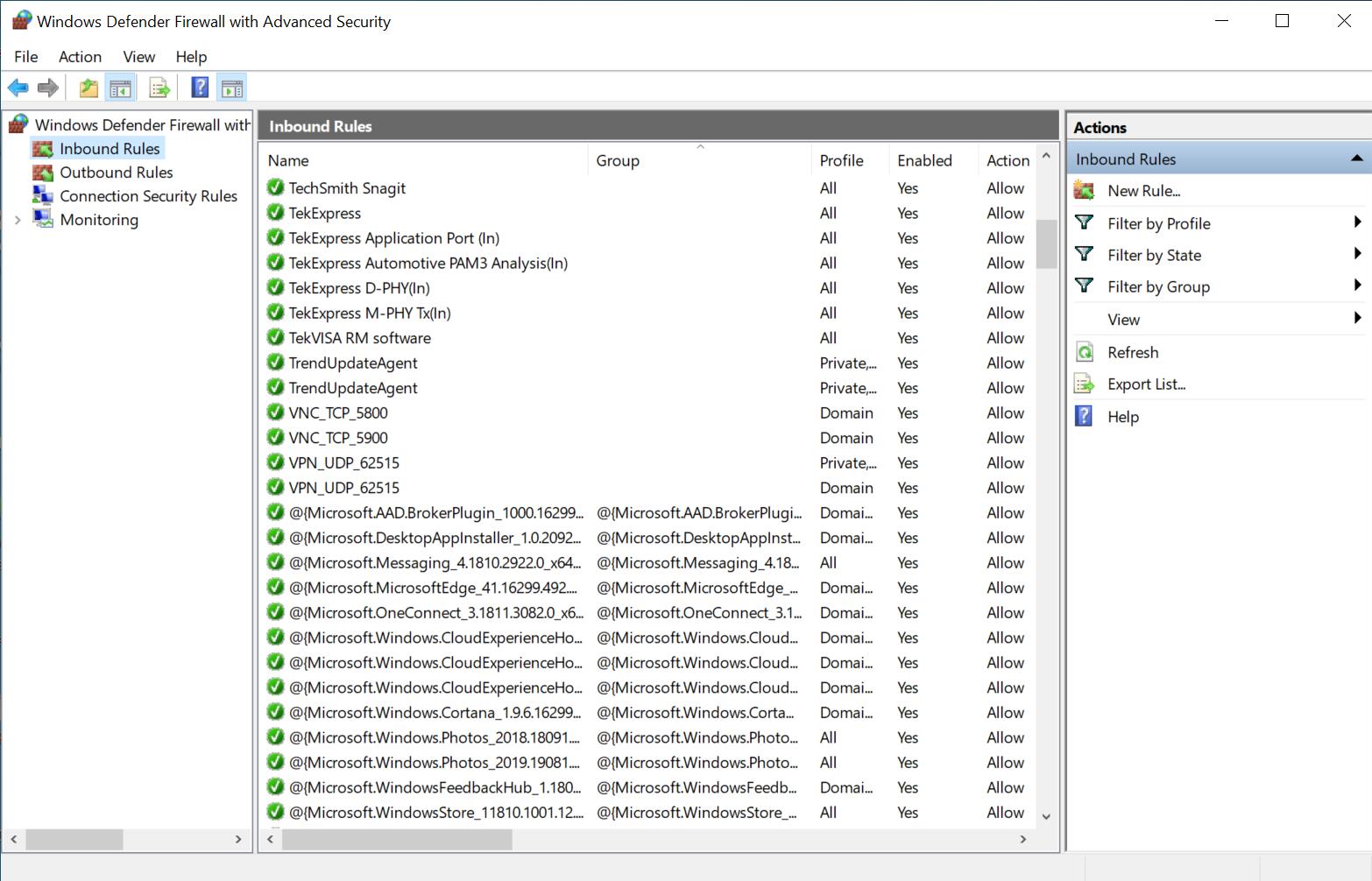
TekVISA configuration
- Click .
- Click Search Criteria. In Search Criteria menu, click LAN to Turn-on. Select Socket from the drop-down list, enter the IP address of the TekExpress device in Hostname and type Port as 5000. Click
Enter the Hostname as 127.0.0.1 if the TekVISA and TekExpress application are in the same system, else enter the IP address of the oscilloscope where the TekExpress application is running.
- Click Search to setup the TCPIP connection with the host. Check whether the TCPIP host name is displayed in .
- Double-click OpenChoice Talker Listener and enter the Command *IDN? in command entry field and click Query. Check that the Operation is successful and Talker Listener Readout displays the Command / Data.
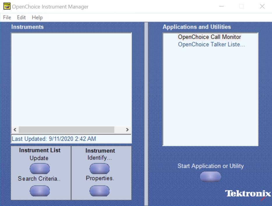

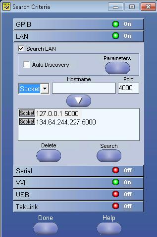
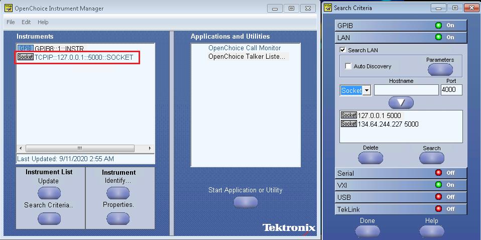
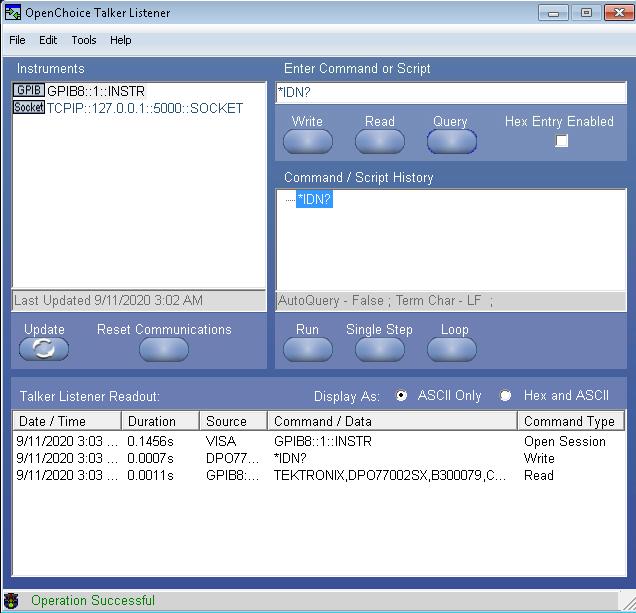
Set or query the device name of application
This command sets or queries the device name of the application.
Syntax
TEKEXP:SELECT DEVICE,"<DeviceName>" (Set)
TEKEXP:SELECT? DEVICE (Query)
Command arguments
| Argument Name | Argument Type |
|---|---|
|
<DeviceName> |
<String> |
Returns
<String>
Examples
TEKEXP:SELECT DEVICE,"<DeviceName>" command sets the device name of the application.
TEKEXP:SELECT? DEVICE command returns the selected device name of the application.
Set or query the suite name of the application
This command sets or queries the suite name of the application.
Syntax
TEKEXP:SELECT SUITE,"<SuiteName>" (Set)
TEKEXP:SELECT? SUITE (Query)
Command arguments
| SuiteName |
|---|
|
Returns
<String>
Examples
TEKEXP:SELECT SUITE,"<SuiteName>" command sets the suite name of the application.
TEKEXP:SELECT? SUITE command returns the selected suite of the application.
Set or query the test name of the application
This command selects or deselects the specified test name of the application.
Syntax
TEKEXP:SELECT TEST,"<TestName>",<Value> (Set)
TEKEXP:SELECT TEST,"<ALL>" (Set)
TEKEXP:SELECT? TEST (Query)
Command arguments
| TestName | Value |
|---|---|
Tests for CEM
| {True | False} or {1 | 0} It represents selected or unselected. Where, True or 1 - Selected False or 0 - Unselected |
| {True | False} or {1 | 0} It represents selected or unselected. Where, True or 1 - Selected False or 0 - Unselected |
|
Tests for BaseSpec
| {True | False} or {1 | 0} It represents selected or unselected. Where, True or 1 - Selected False or 0 - Unselected |
Tests for U.2
| {True | False} or {1 | 0} It represents selected or unselected. Where, True or 1 - Selected False or 0 - Unselected |
Tests for M.2
| {True | False} or {1 | 0} It represents selected or unselected. Where, True or 1 - Selected False or 0 - Unselected |
Test for RefClockSpec
| {True | False} or {1 | 0} It represents selected or unselected. Where, True or 1 - Selected False or 0 - Unselected |
Returns
{True | False} or {1 | 0}
Examples
TEKEXP:SELECT TEST,"<TestName>",1 command selects the specified test in the Test Panel.
TEKEXP:SELECT TEST,"<ALL>" command select all the tests in the Test Panel.
TEKEXP:SELECT? TEST command returns the list of selected tests.
Set or query the version name of the application
This command sets or queries the version name of the application.
Syntax
TEKEXP:SELECT VERSION,”<VersionName>” (Set)
TEKEXP:SELECT? VERSION (Query)
Command arguments
| Argument Name | Argument Type | Valid Values |
|---|---|---|
| <VersionName> | <String> | It is the name of the version on the DUT panel of the application. |
| VersionName | ||
|
Returns
<String>
Examples
TEKEXP:SELECT VERSION,”<VersionName>” command sets the version name of application.
TEKEXP:SELECT? VERSION command returns the version name of application.
Set or query the general parameter values
This command sets or queries the general parameter values of the application.
Syntax
TEKEXP:VALUE GENERAL,"<ParameterName>","<Value>" (Set)
TEKEXP:VALUE? GENERAL,"<ParameterName>" (Query)
Command arguments
| ParameterName | Value |
|---|---|
| Value |
Specifies the value parameters.
|
| InstrumentType |
Specifies the instrument type. Valid values are:
|
| DataRate2Gb |
|
| DataRate5Gb |
|
| DataRate8Gb |
|
| DataRate16Gb |
|
| DataRate32Gb |
|
| DataRate64Gb |
|
| PreEmphasis3dB |
|
| PreEmphasis6dB |
|
| SSC |
|
| VoltageSwing |
|
| Link Widths |
|
| SignalPreset8Gb |
Signal quality preset selection values are P0, P1, P2, P3, P4, P5, P6, P7, P8, P9, P10. To select multiple signal quality preset, specify as P0_P1_P2 |
| SignalPreset16Gb | |
| SignalPreset32Gb | |
| Preset8Gb |
Preset selection values are P0_, P1_, P2_, P3_, P4_, P5_, P6_, P7_, P8_, P9_, P10_. To select multiple signal quality preset, specify as P0_P1_P2 |
| Preset16Gb | |
| Preset32Gb | |
| Preset64Gb |
Preset selection values are Q0_, Q1_, Q2_, Q3_, Q4_, Q5_, Q6_,Q7_, Q8_, Q9_, Q10_. To select multiple signal quality preset, specify as Q0_Q1_Q2 |
| Acquisition |
|
| AcquisitionCountGen4 | 1 to 10 |
| AcquisitionCountGen5 | |
| SaveOptions |
|
| DeEmbed2Gb |
|
| DeEmbed5Gb |
|
| DeEmbed8Gb |
|
| DeEmbed16Gb |
|
| DeEmbed32Gb |
|
| DeEmbed64Gb |
|
| Embed8Gb |
|
| Embed16Gb |
|
| Embed32Gb |
|
| Filterfile2Gb | Filterfile2Gb.flt |
| Filterfile5Gb | Filterfile5Gb.flt |
| FilterfileDeEmbed8Gb | FilterfileDeEmbed8Gb.flt |
| FilterfileEmbed8Gb | FilterfileEmbed8Gb.flt |
| FilterfileDeEmbed16Gb | FilterfileDeEmbed16Gb.flt |
| FilterfileEmbed16Gb | FilterfileEmbed16Gb.flt |
| FilterfileDeEmbed32GbPos | FilterfileDeEmbed32GbPos.flt |
| FilterfileDeEmbed32GbNeg | FilterfileDeEmbed32GbNeg.flt |
| FilterfileDeEmbed64GbPos | FilterfileDeEmbed64GbPos.flt |
| FilterfileDeEmbed64GbNeg | FilterfileDeEmbed64GbNeg.flt |
| FilterfileEmbed32Gb | FilterfileEmbed32Gb.flt |
| FilterfileDeEmbed32Gb | FilterfileDeEmbed32Gb.flt |
| EnableDUTAutomation |
|
| DeskewAutomation |
|
| Automation Settings |
|
| Signal Type |
|
| Gen4DataClockPatternCount | 0 to 9 |
| Gen5DataClockPatternCount | 0 to 9 |
| RecordLength2Gb | 2.5e6 |
| RecordLength5Gb | 10e6 |
| RecordLength8Gb | 10e6 |
| RecordLength16Gb | 20e6 |
| RecordLength32Gb | 12.5e6 |
| RecordLength64Gb | 12.5e6 |
| SampleRate2Gb | 50e9 |
| SampleRate5Gb | 50e9 |
| SampleRate8Gb | 50e9 |
| SampleRate16Gb | 100e9 |
| SampleRate32Gb | 200e6 |
| SampleRate64Gb | 200e6 |
| Bandwidth2Gb | 6e9 |
| Bandwidth5Gb | 12.5e9 |
| Bandwidth8Gb | 13e9 |
| Bandwidth16Gb | 16e9 |
| Bandwidth32Gb |
|
| Bandwidth64Gb | 50e9 |
| Signal Validation |
|
| SqSigtestPathGen3 |
Sigtest file path. Example: C:\Program Files (x86)\SigTest 4.0.51\SigTest.exe |
| PresetSigtestPathGen3 | |
| SqtestPathGen4 | |
| PresetSigtestPathGen4 | |
| SqtestPathGen5 | |
| PresetSigtestPathGen5 | |
| PHYSigtestPathGen5 | |
| SigtestTemplate2Gbps | |
| SigtestTemplate5Gbps3Db | |
| SigtestTemplate5Gbps6Db | |
| SigtestTemplate8Gbps | |
| SigtestTemplate16Gbps | |
| SigtestTemplate32GbpsJitterMeas | |
| SigtestTemplate32GbpsVoltageMeas | |
| SigtestTemplate16GbpsPwjTest | |
| SigtestTemplate32GbpsPHYTest | |
| SigtestTemplate32GbpsSignalTest | |
| Include Intermediate Results |
|
| Awg Clock Setup |
|
| SRIS SSC |
|
| SlotNumber | 05 |
| Scope Noise Auto Mode |
|
| CTLE Auto Mode |
|
| CTLERecordLength | Value: 1.0 to 20.0 |
| OptimalCTLEValue | Value: 0.0 to 15.0 |
| CTLEStepSize |
|
| Scope Noise Compensation (SNDR) | Value: 0.0 to 20.0 |
| Scope Noise Compensation (TIE Jitter) | Value: 0.0 to 20.0 |
| Scope Noise Compensation (PWJ) | Value: 0.0 to 20.0 |
| Signal Validation Threshold(mV) | 200 |
| Report Update Mode |
|
| Trigger Type |
|
| DUTID Comment |
User comment |
| Timer Warning Info Message Popup |
|
| Timer Warning Info Message Popup Duration | 0 to 20 |
| Timer Error Message Popup |
|
| Timer Error Message Popup Duration | 0 to 20 |
| On Failure Stop and Notify | True or False |
| Automate with Switch | True or False |
| DeskewAlertEnabled | True or False |
| On Failure Stop and Notify | True or False |
| On Failure Pause | True or False |
| JitterTestAcquireType (For Basespec Only) |
|
| SigtestSilentMode | True or False |
| Gen5RefClockData (For RefClockSpecOnly) | True or False |
| SiliconLabTool (For RefClockSpecOnly) | True or False |
| Probing Type (For All) |
|
| RecordLengthRefGen5 (For RefClockSpec Only) | 80e6 |
| SampleRateRefGen5 (For RefClockSpec Only) | 50e9 |
| BandwidthRefGen5 (For RefClockSpec Only) | 5e9 |
| ParameterName | Value |
|---|---|
| Report Update Mode |
|
| Report Path |
X:\<application name>\Reports\DUT001.mht |
| Save As Type |
|
| Auto increment report name if duplicate | {True | False} or {1 | 0} It represents selected or unselected. Where,
|
| Create report at the end | {True | False} or {1 | 0} It represents selected or unselected. Where,
|
| Include Pass/Fail Results Summary | {True | False} or {1 | 0} It represents selected or unselected. Where,
|
| Include Detailed Results | {True | False} or {1 | 0} It represents selected or unselected. Where,
|
| Include Plot Images | {True | False} or {1 | 0} It represents selected or unselected. Where,
|
| Include Setup Configuration | {True | False} or {1 | 0} It represents selected or unselected. Where,
|
| CXL Report Selection |
|
| Include Complete Application Configuration | {True | False} or {1 | 0} It represents selected or unselected. Where,
|
| Include User Comments | {True | False} or {1 | 0} It represents selected or unselected. Where,
|
Returns
<NRf> or <String>
Examples
TEKEXP:VALUE GENERAL,"<ParameterName>","<Value>" command set the value for the specified general parameter.
TEKEXP:VALUE? GENERAL,"<ParameterName>" command returns the value for the specified general parameter.
Query the available devices in the DUT panel of the application
This command queries the list of available devices on the DUT panel as comma separated values.
Syntax
TEKEXP:LIST? DEVICE (Query)
Command arguments
| Device | Device Type and value | Description |
|---|---|---|
| <Device> |
| It is the name of the device on the DUT panel of the application. |
Returns
<String>
Examples
TEKEXP:LIST? DEVICE command returns the list of available devices.
Query the available suites for the selected device
This command queries the list of available suites for the selected device as comma separated values.
Syntax
TEKEXP:LIST? SUITE (Query)
Returns
<String>
Examples
TEKEXP:LIST? SUITE command returns the list of available suites for the selected device.
Query the list of available tests of the application
This command queries the list of available tests of the application for the selected device as comma separated values.
Syntax
TEKEXP:LIST? TEST (Query)
Command arguments
| TestName | String |
|---|---|
| Tests for CEM |
|
| Tests for BaseSpec |
|
| Tests for U.2 |
|
| Tests for M.2 |
|
| Test for RefClockSpec |
|
Returns
<String>
Examples
TEKEXP:LIST? TEST command returns the list of available tests for the selected device.
Query the available version names of the application
This command queries the list of available version names of the application for the selected device as comma separated values.
Syntax
TEKEXP:LIST? VERSION (Query)
Returns
<String>
Examples
TEKEXP:LIST? VERSION command returns the list of version names for the selected device.
Query the list of available instruments based on the specified instrument type
This command queries the list of available instruments based on the specified instrument type.
Syntax
TEKEXP:LIST? INSTRUMENT,"<InstrumentType>" (Query)
Command argument
| Argument Name | Argument value |
|---|---|
| <InstrumentType> | <String> |
Returns
<String>
Examples
TEKEXP:LIST? INSTRUMENT,"Real Time Scope" command returns the list of available instruments based on the real time scope type.
Set or query the IP address of the instrument based on the specified instrument type
This command sets or queries the IP address of the instrument based on the specified instrument type.
Syntax
TEKEXP:INSTRUMENT? "<InstrumentType>" (Query)
TEKEXP:INSTRUMENT, "<InstrumentType>","<Value>" (Set)
Command argument
| Argument Name | Argument Type |
|---|---|
| <InstrumentType> | <String> |
| <Value> | <String> TCPIP::XXX.XX.XXX.XXX::INSTR |
Returns
<String>
Examples
TEKEXP:INSTRUMENT? "<InstrumentType>" command returns the IP address of the oscilloscope.
TEKEXP:INSTRUMENT, "<InstrumentType>","<value>" command sets the oscilloscope to the specified IP address.
Query the information of the generated report file
This command queries the information of the generated report file in the format "<FileSize>","<FileName>".
Pre‐requisite
A session should be run earlier and the report should be generated to get the information of the report.
Syntax
TEKEXP:INFO? REPORT (Query)
Returns
<FileSize>:: <String>
<FileName>:: <String>
Examples
TEKEXP:INFO? REPORT command returns the information of the generated report in the format ("1215”,"DUT001.mht”).
Query the information of the generated waveform files
This command queries the information of the generated waveform files in the format.
<File1Size,"File1Name”>.
If there are more than one waveform, the waveform file names are displayed with the comma separated values in the format
<File1Size,"File1Name">,<File2Size,"File2Name">.
Syntax
TEKEXP:INFO? WFM (Query)
Returns
<FileSize>:: <String>
<FileName>:: <String>
Examples
TEKEXP:INFO? WFM command returns the information of the generated waveform in the format (20000858,"X:\PCI Express\Untitled Session\DUT001\20200916_041609\Iter1_Short Record‐length for SCOPE Period_NoSSC_DIFF.wfm”).
Query the information of the generated image files
This command queries the information of the generated image files in the format.
<File1Size,"File1Name”>.
If there are more than one image, the image file names are displayed with the comma separated values in the format
<File1Size,"File1Name">,<File2Size,"File2Name">.
Syntax
TEKEXP:INFO? IMAGE (Query)
Returns
<FileSize>:: <String>
<FileName>:: <String>
Examples
TEKEXP:INFO? IMAGE command returns the information of the generated image in the format (109058, "X:\PCI Express\Untitled Session\DUT001\20200916_041609\Iter1_Short Record‐length for SCOPE Period_NoSSC_DIFF.png";22794,"X:\PCI Express\UntitledSession\DUT001\20 200916_041609\ScopePeriodPlot_Iteration1WithCursor.png").
Query the active TekExpress application name
This command queries the active TekExpress application name running on the oscilloscope.
Syntax
TEKEXP:*IDN? (Query)
Returns
<String>
Examples
TEKEXP:*IDN? command returns the active TekExpress application name running on the oscilloscope.
Set or query the DUTID of application
This command sets or queries the DUTID of the application.
Syntax
TEKEXP:VALUE DUTID,"<Value>" (Set)
TEKEXP:VALUE? DUTID (Query)
Command arguments
| Argument Name | Argument Type |
|---|---|
| <Value> | <String> |
Returns
<String>
Examples
TEKEXP:VALUE DUTID,"DUT001" command sets the DUTID of the application to DUT001.
TEKEXP:VALUE? DUTID command returns the DUTID of the application.
Sets or query the acquire mode status
This command sets or queries the acquire mode status.
Syntax
TEKEXP:ACQUIRE_MODE <Mode> (Set)
TEKEXP:ACQUIRE_MODE? (Query)
Command arguments
| Argument Name | Argument value |
|---|---|
| <Mode> |
|
Returns
LIVE | PRE‐RECORDED
Examples
TEKEXP:ACQUIRE_MODE LIVE command sets the acquire mode to the Live mode.
TEKEXP:ACQUIRE_MODE? command returns the current acquire mode.
Set or query the execution mode status
This command sets or queries the execution mode status.
Syntax
TEKEXP:MODE <Mode> (Set)
TEKEXP:MODE? (Query)
Command arguments
| Argument Name | Argument value |
|---|---|
| <Mode> |
|
Returns
COMPLIANCE | USER‐DEFINED
Examples
TEKEXP:MODE COMPLIANCE command sets the execution mode to the compliance mode.
TEKEXP:MODE? command returns the current execution mode.
Generate the report for the current session
This command generates the report for the current session.
Syntax
TEKEXP:REPORT GENERATE(Set)
Arguments
N/A
Examples
TEKEXP:REPORT GENERATE command generates the report for the current session.Query the value of specified report header field in the report
This command queries the value of specified report header field in the report.
Syntax
TEKEXP:REPORT? ”<Device Field>” (Query)
Command arguments
| Argument Name | Argument Type |
|---|---|
| <Device Field> Device field is the header name of each field in the setup information section of the report. 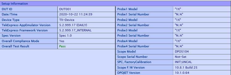 | <String> |
Returns
<String>
Examples
TEKEXP:REPORT? "DUT ID" command returns the value of DUT ID field in the report.
Query the value of specified result detail available in report summary/details table
This command queries the value of specified result detail available in report summary/details table.
Syntax
TEKEXP:RESULT? "<TestName>" (Query)
TEKEXP:RESULT? "<TestName>","<ColumnName>" (Query)
TEKEXP:RESULT? "<TestName>","<ColumnName>",<RowNumber> (Query)
Command arguments
| Argument Name | Argument Type |
|---|---|
| <TestName> It is the test name of which the details are required in the report. | <String> |
| <ColumnName> It is the column header name of which the details are required in the report. | <String> |
| <RowNumber> It is the row number of which the details are required in the report. | <String> |
Returns
<String>
Examples
TEKEXP:RESULT? "<TestName>" will return the pass fail status of test.
TEKEXP:RESULT? "<TestName>","<ColumnName>" will return all the row values of specific column for the test with comma separated values.
TEKEXP:RESULT? "<TestName>","<ColumnName>",<RowNumber> will return the column value of specified row number.
Restore the setup to default settings
This command restores the setup to default settings.
Syntax
TEKEXP:SETUP Default(Set)
Arguments
N/A
Examples
TEKEXP:SETUP Default command restores the setup to default settings.
Save the setup
This command saves the setup.
Syntax
TEKEXP:SETUP Save(Set)
Examples
TEKEXP:SETUP Save command saves the setup.
Save the settings to a specified session
This command saves the settings to a specified session.
Syntax
TEKEXP:SETUP Save,"<SessionName>"
Command arguments
| Argument Name | Argument value |
|---|---|
| <SessionName> | <String> |
Examples
TEKEXP:SETUP Save,"<SessionName>" command saves the settings to a specified session.
Open the setup from a specified session
This command opens the setup from a specified session.
Syntax
TEKEXP:SETUP Open,"<SessionName>"(Set)
Command arguments
| Argument Name | Argument value |
|---|---|
| <SessionName> | <String> |
Examples
TEKEXP:SETUP Open,"<SessionName>" command opens the setup from a specified session.
Query the current setup file name
This command queries the current setup file name.
Syntax
TEKEXP:SETUP? CURRENT (Query)
Returns
<String>
Examples
TEKEXP:SETUP? CURRENT command returns the current setup file name.
Run/stop/pause/resume the selected measurements execution in the application
This command run/stop/pause/resume the selected measurements execution in the application.
Syntax
TEKEXP:STATE <operation mode> (Set)
Command arguments
| Argument Name | Argument value |
|---|---|
| <operation mode> |
|
Returns
RUN | STOP | PAUSE | RESUME
Examples
TEKEXP:STATE RUN command runs the execution for the selected measurements.
Query the current measurement execution status
This command queries the current measurement execution status.
Syntax
TEKEXP:STATE? (Query)
Returns
RUNNING | PAUSED | WAIT | ERROR | READY
Examples
TEKEXP:STATE? command returns the current measurement execution status.
Query whether the current setup is saved or not saved
This command queries whether the current setup is saved or not saved.
Syntax
TEKEXP:STATE? SETUP (Query)
Returns
Saved or Not‐Saved
Examples
TEKEXP:STATE? SETUP command returns whether the current setup is saved or not saved.
Query the status of the previous command execution
This command queries whether the previous command execution is completed successfully.
Syntax
TEKEXP:*OPC? (Query)
Returns
{0 | 1} or {True | False}
1 or True indicates that command execution is successful.
0 or False indicates that command execution is failed.
Examples
TEKEXP:*OPC? command returns whether the previous command operation is completed successfully.
Query the last error occurred
This command queries the last error occurred.
Syntax
TEKEXP:LASTERROR? (Query)
Returns
<String>
Examples
TEKEXP:LASTERROR? command returns the last error occurred.
Set or query the popup details
This command sets or queries the popup details.
Syntax
TEKEXP:POPUP? (Query)
TEKEXP:POPUP "<PopupResponse>" (Set)
Command arguments
| Argument Name | Argument value |
|---|---|
| <PopupResponse> |
|
Returns
The pop‐up details return in the following format:
"<Tittle>","<message>","<response1>,<response2>".
Where,
<Tittle> :: <String>
<message> :: <String>
<response1>,<response2> :: <String>
Examples
TEKEXP:POPUP? command returns the popup details in following format ": "Do you really want to exit TekExpress?";Responses: "Yes, No".
TEKEXP:POPUP "Yes" command sets the popup response to Yes.
Sets or query the limit values in the limits editor window
This command sets or queries the limit values in the limits editor window.
Syntax
TEKEXP:VALUE LIMIT,<TestName>,<LimitHeader>,<Value1>,<CompareString>,<Value2>(Set)
TEKEXP:VALUE? LIMIT,<TestName>,<LimitHeader> (Query)
Returns
<String> or <NRf>
Examples
TEKEXP:VALUE LIMIT,<TestName>,<LimitHeader>,<Value1>,<CompareString>,<Value2> command sets the limits value for the specified testname and limit header.
TEKEXP:VALUE? LIMIT,<TestName>,<LimitHeader> command returns the limits value for the specified testname and limit header.
Set or query the waveform file recalled for the specified test name and acquire type
This command set or queries the waveform file recalled for the specified test name and acquire type.
If there are more than one waveform, the waveform file names are displayed with the symbol "$" separated values in the format
<WaveformFileName1$ WaveformFileName2>.
Syntax
TEKEXP:VALUE WFMFILE,<TestName>,<AcquireType>,<WaveformFileName> (Set)
TEKEXP:VALUE? WFMFILE,<TestName>,<AquireType> (Query)
Returns
<String>
Examples
TEKEXP:VALUE WFMFILE,<TestName>,<AquireType>,<WaveformFileName> command recalls the sepcified waveform file for the specified testname and acquire type.
TEKEXP:VALUE? WFMFILE,<TestName>,<AquireType> command returns the waveform file name recalled for the specified testname and acquire type.
Set or query the enable/disable status of Verbose function
This command sets or queries the enable/disable status of Verbose function.
Syntax
TEKEXP:VALUE VERBOSE,"<Value>" (Set)
TEKEXP:VALUE? VERBOSE (Query)
Arguments
| Argument Name | Argument value |
|---|---|
| <Value> | {True | False} or {1 | 0} It represents enabled or disabled. Where,
|
Returns
{True | False} or {0 | 1}
Examples
TEKEXP:VALUE VERBOSE,"<Value>" command enable or disable the Verbose function.
TEKEXP:VALUE? VERBOSE command returns the enable or disable status of Verbose function.
Set or query the View report after generating option status
This command sets or queries the enable/disable status of the View report after generating function.
Syntax
TEKEXP:VALUE? GENERAL,"View Report After Generating" (Query)
TEKEXP:VALUE GENERAL,"View Report After Generating",<value> (Set)
Arguments
| Argument Name | Argument value |
|---|---|
| <Value> | {True | False} or {1 | 0} It represents enabled or disabled. Where,
|
Returns
{True | False} or {0 | 1}
Examples
TEKEXP:VALUE? GENERAL,"View Report After Generating" command returns the enable or disable status of view report after generating option.
TEKEXP:VALUE GENERAL,"View Report After Generating",<value> command enable or disable the view report after generating option.
Returns the report as XML string
This command returns the report as XML string.
Syntax
TEKEXP:REPORTASXML? (Query)
Returns
<String>
Examples
TEKEXP:REPORTASXML? command returns the report XML string.
Copies all the images from current run session to the given destination location
This command copies all the images from current run session to the given destination location.
Syntax
TEKEXP:COPYIMAGES <DestinationPath> (Set)
Command argument
<DestinationPath> :: <String>
Returns
NA
Examples
TEKEXP:COPYIMAGES C:\Temp command copies all the images from current run session to the mentioned location.
Selects the specified test(s) and deselect all other tests
This command selects the specified test(s) and deselect all other tests.
Syntax
TEKEXP:SELECTID <”TestID”> (Set)
Command argument
| Argument Name | Argument value |
|---|---|
| TestID | String |
Returns
NA
Examples
TEKEXP:SELECTID "11101"This command select the test associated with the ID and deselects all other tests in the application.
TEKEXP:SELECTID “11101,11102”This command selects the tests associated with the IDs and other tests will be deselected.
Returns the complete information about the selected test
This command returns the complete information about the selected test.
The information includes application name, TestID, Device selected, Suite selected, version, Test name, Test description.
Syntax
TEKEXP:TESTINFO? (Query)
Returns
<String>
Examples
TEKEXP:TESTINFO? This command returns the following details:
<TekExpress> <Test Id="11101" Device="TX-Device" Suite="Group1" Version="Spec 1.0" Name="Algorithm Library Measurement" Description="This is Algorithm Library measurement test. Refer Section-B of TekExpress SampleApp Development Guide for more details.
Set the default session
Sets the application configurations to default value.
Syntax
TEKEXP:SESSION DEFAULT (set)
Examples
TEKEXP:SESSION DEFAULT, sets the application configurations to default value.
Save the run/config sessions
Enter the name to save/config the session.
Syntax
TEKEXP:SESSION SAVE,“Session Name” (set)
Command arguments
| Argument Name | Argument value |
|---|---|
| <Session Name> | <String> |
Examples
TEKEXP:SESSION SAVE,“Session Name” saves the session.
Load the run/config session
Load the selected config/run session.
Syntax
TEKEXP:SESSION LOAD, “Session Name” (set)
Command arguments
| Argument Name | Argument value |
|---|---|
| <Session Name> | <String> |
Examples
TEKEXP:SESSION LOAD, “Session Name”, load the selected config/run session.
Delete the run/config session
Deletes the selected config/run session.
Syntax
TEKEXP:SESSION DELETE, "Session1, Session2" (set)
Command arguments
| Argument Name | Argument value |
|---|---|
| <Session Name> | <String> |
Examples
TEKEXP:SESSION DELETE, "Session1, Session2", deletes the selected config/run session.
Run the run/config saved session
Run the selected config/run session.
Syntax
TEKEXP:SESSION RUN, “Session Name’s separated by comma” (set)
Command arguments
| Argument Name | Argument value |
|---|---|
| <Session Name> | <String> |
| Session Name’s separated by comma (to run the multiple run sessions) | <String> |
Examples
TEKEXP:SESSION RUN, “Session Name’s separated by comma”, runs the selected config/run session.
Query the available list in the run/config session
Returns the list of available config/run session.
Syntax
TEKEXP:SESSION? LIST
Returns
Returns the list of available config/run session.
Examples
TEKEXP:SESSION? LIST, returns the list of available config/run session.
Query the current run/config session
Returns the selected config/run session.
Syntax
TEKEXP:SESSION? CURRENT
Returns
Returns the selected config/run session.
Examples
TEKEXP:SESSION? CURRENT, returns the selected config/run session.
Override the run/config session
Overrides the selected config/run session.
Syntax
TEKEXP:SESSION SAVE,"SessionName", "True" (set)
Command arguments
| Argument Name | Argument Type | Argument Value |
|---|---|---|
| <Session Name> | <String> | {True | False} or {1 | 0} It represents enabled or disabled. Where,
|
Returns
{True | False} or {0 | 1}
Examples
TEKEXP:SESSION SAVE,"SessionName", "True", overrides the selected config/run session.
Exit or close the application
The command exits or close the application
Syntax
TEKEXP:EXIT(Set)
Examples
TEKEXP:EXIT command close the application.
Examples
import sys
from time import sleep
import platform
import os
import traceback
import socket_instrument
import csv
_dutId = 'Test DUTID'
_deviceName = "CEM"
_suiteName = "Add-In-Card"
_versionName = "Gen1 - 1.1"
[_param, _value] = ['Signal Validation', 'Turn Off Signal Check']
_measList = ['Unit Interval Gen1']
#No need to change the IP address as it is running on same machine
ipAddress = "localhost"
si = socket_instrument.SocketInstrument(ipAddress, 5000)
print si.instId
# Set DUTID
si.write('TEKEXP:VALUE DUTID,"{0!s}"'.format(_dutId))
print si.query('TEKEXP:VALUE? DUTID')
# Set device
si.write('TEKEXP:SELECT DEVICE,"{0!s}"'.format(_deviceName))
while si.query('TEKEXP:SELECT? DEVICE') != '"{}"'.format(_deviceName):
sleep(1)
print si.query('TEKEXP:SELECT? DEVICE')
# Set test suite
si.write('TEKEXP:SELECT SUITE,"{0!s}"'.format(_suiteName))
while si.query('TEKEXP:SELECT? SUITE') != '"{}"'.format(_suiteName):
sleep(1)
print si.query('TEKEXP:SELECT? SUITE')
# Set test version
si.write('TEKEXP:SELECT VERSION,"{0!s}"'.format(_versionName))
while si.query('TEKEXP:SELECT? VERSION') != '"{}"'.format(_versionName):
sleep(1)
print si.query('TEKEXP:SELECT? VERSION')
# Set Signal Validation to 'Turn Off'
si.write('TEKEXP:VALUE GENERAL,"{0!s}","{1!s}"'.format(_param, _value))
print si.query('TEKEXP:VALUE? GENERAL,"{0!s}"'.format(_param))
# Assign Test name
si.write('TEKEXP:SELECT TEST,ALL,FALSE')
sleep(2)
for _meas in _measList:
si.write('TEKEXP:SELECT TEST,"{0!s}",TRUE'.format(_meas))
sleep(2)
selectedMeasurements = si.query('TEKEXP:SELECT? TEST')
selectedMeasurements = selectedMeasurements.replace('"','').split(',')
#print 'Selected Measurements'
#for meas in selectedMeasurements:
#print meas
# if any General Parameters User want to modify can be done here
# Execution Starts
"""Execution function with popup handling"""
appStatus = si.query('TEKEXP:STATE?')
if appStatus == 'READY':
si.write('TEKEXP:STATE RUN')
while str(si.query('TEKEXP:STATE?')) != 'RUNNING':
sleep(1)
appStatus = si.query('TEKEXP:STATE?')
try:
while str(appStatus) != 'READY':
appStatus = si.query('TEKEXP:STATE?')
if appStatus in ['RUNNING']:
sleep(2)
print('Application Status: ..{}..'.format(appStatus))
if appStatus in ['WAIT','ERROR']:
print('\n----------------------------------------')
print('Application Status: {} Message'.format(appStatus))
info = str(si.query('TEKEXP:POPUP?'))
[Title, Message, Responses] = info.split(';')
ResponseOptions = str(Responses[12:-1]).strip('"')
ResponseOptions = ResponseOptions.split(',')
print('\n\n'+Title+'\n\n'+Message+'\n')
print("----------------------------------------")
for res in ResponseOptions:
print str(ResponseOptions.index(res)) + ' > ' + res
userResponse = int(input('Choose your option: '))
si.write('TEKEXP:POPUP "{0!s}"'.format(ResponseOptions[userResponse]))
print('\nResponse Sent: "{0!s}"'.format(ResponseOptions[userResponse]))
print("----------------------------------------")
print("***** EXECUTION COMPLETED *****")
except Exception:
print("Exception Occured")
# Get the Measurement Results
allDetailsList = list()
allValuesList = list()
allMarginList = list()
for meas in _measList:#selectedMeasurements:
allDetailsList = (si.query('TEKEXP:RESULT? "{0!s}","{1!s}"'.format(meas,'Details'))).replace('"','').split(',')
allValuesList = (si.query('TEKEXP:RESULT? "{0!s}","{1!s}"'.format(meas,'Value'))).replace('"','').split(',')
allMarginList = (si.query('TEKEXP:RESULT? "{0!s}","{1!s}"'.format(meas,'Margin'))).replace('"','').split(',')
results = zip(allDetailsList, allValuesList, allMarginList)
# Define local variables
testResultList = list()
details = list()
values = list()
margines = list()
# Header Info for the CSV file
header1CSV=["Detail"]
header2CSV=["Value"]
header3CSV=["Margin"]
header=zip(header1CSV,header2CSV,header3CSV)
testResultList.append(header)
# Convertion to suitable for CSV formatting
testResultList.append(results)
# Open a CSV file object
csvFilePath = "C:\\Test_PCI_Results.csv"
csvFilObj = open(csvFilePath,"wb")
# writing CSV file with the statistical values
mywritter=csv.writer(csvFilObj)
for rowVal in testResultList:
mywritter.writerows(rowVal)
# Closing the CSV file object
csvFilObj.close()
si.disconnect()
References
Application directories
You can find the application files at C:\Program Files\Tektronix\TekExpress PCI Express. The application directory and associated files are organized as follows:
| Directory names | Usage |
|---|---|
| Bin | Contains application libraries |
| Compliance Suites | Contains test suite specific files |
| Examples | Contains various support files |
| ICP | Contains instrument and application specific interface libraries |
| Images | Contains images of the application |
| Lib | Contains utility files specific to the application |
| Licenses | Contains all the license files |
| Report Generator | Contains style sheets for report generation |
| Tools | Contains instrument and application specific files |
File name extensions
The TekExpress PCIe application uses the following file name extensions:
|
File name extension |
Description |
|---|---|
|
.TekX |
Application session files (the extensions may not be displayed) |
|
.py |
Python test file. See the TekExpress PCI Express\Examples folder for a sample file |
|
.xml |
Test-specific configuration information (encrypted) file Application log file |
|
.wfm |
Test waveform file |
|
.mht |
Test result reports (default). Test reports can also be saved in HTML format |
|
.flt |
Filter files |
|
.chm, pdf |
Help manuals |
Waveform file names
This application uses file name conventions to access the waveforms. It is recommended to save the waveforms with following file names.
-
Differential data waveform: Tek_PCIe_Slot_DataRate_LaneNumber_PresetNumber_Data_Differential.wfm
Example: Tek_PCIe_01_8Gbps_Ln00_P0_d_Diff.wfm
-
Differential clock waveform: Tek_PCIe_Slot_DataRate_LaneNumberClk_PresetNumber_Data_Differential.wfm
Example: Tek_PCIe_01_8Gbps_Ln00Clk_P0_d_Diff.wfm
-
Single ended data positive waveform: Tek_PCIe_Slot_DataRate_LaneNumber_PresetNumber_Data_Pos.wfm
Example: Tek_PCIe_01_8Gbps_Ln00_P0_d_Pos.wfm
-
Single ended data negative waveform: Tek_PCIe_Slot_DataRate_LaneNumber_PresetNumber_Data_Neg.wfm
Example: Tek_PCIe_01_8Gbps_Ln00_P0_d_Neg.wfm
See also
View test-related files
Files related to tests are stored in the
My TekExpress\PCI Express folder. Each test setup in this folder has a test setup file and a test setup folder, both with the test setup name.
The test setup file is preceded by the TekExpress icon and usually has no visible file name extension.
Inside the test setup folder is another folder named for the DUT ID used in the test sessions. The default is DUT001.
Inside the DUT001 folder are the session folders and files. Each session also has a folder and file pair, both named for the test session using the naming convention (date)_(time). Each session file is stored outside its matching session folder:
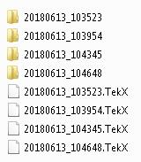
Each session folder contains image files of any plots generated from running the test session. If you selected to save all waveforms or ran tests using prerecorded waveform files, these are included here.
The first time you run a new, unsaved session, the session files are stored in the
Untitled Session folder located at
..\My TekExpress\PCI Express. When you name and save the session, the files are placed in a folder with the name that you specify. A copy of the test files stay in the Untitled Session folder until you run a new test or until you close the PCIe application.
See also
De-embed using filter files
TekExpress PCIe provides an option to de-embed the signal path using filter files. You create the filter files. The filter files are .flt files composed of de-embed filter coefficients for a particular sampling rate. A filter file created for one sampling rate might not work for other sampling rates, so it is important to understand at what sampling rate the measurements are being performed.
Also, the de-embedding filters might differ based on the type of input. For example, if a single ended input is made using a matched SMA cable pair, a filter file for de-embedding a single SMA cable must be provided, since matched SMA cables mostly have similar s-parameters. So in this case, the same filter file is used to de-embed the SMA cable pair.
The maximum sampling rate provided on any channel combination on MSO/DPO/DSA70000/C/D/DX series oscilloscopes is 50 GS/s in realtime mode. The maximum sampling rate provided on Ch1-Ch3 and Ch2-Ch4 channel combinations on MSO/DPO/DSA70000C/D/DX/SX series oscilloscopes is 100 GS/s, provided only 2 channels are on at a given time.
See also
Setup files
TekExpress PCI Express package contains setup files (*.TekX) which can be used at PCI-SIG workshop for compliance tests.
| Setup files (*.TekX) | Configuration details (exclusively used in Gen1/2/3 Gold Suite of PCI-SIG Work Shop (WS)) |
|---|---|
|
Compliance_CEM_AIC _x1 |
|
|
Compliance_CEM_AIC_x2 |
|
|
Compliance_CEM_AIC _x4 |
|
|
Compliance_CEM_AIC_x8 |
|
|
Compliance_CEM_AIC _x16 |
|
|
Compliance_CEM_SYB_x1 |
|
|
Compliance_CEM_SYB_x2 |
|
|
Compliance_CEM_SYB_x4 |
|
|
Compliance_CEM_SYB_x8 |
|
|
Compliance_CEM_SYB_x16 |
|
|
Compliance_U2_Module_x1 |
|
|
Compliance_U2_Module_x2 |
|
|
Compliance_U2_Module_x4 |
|
|
Compliance_U2_Host_x1 |
|
|
Compliance_U2_ Host _x2 |
|
|
Compliance_U2_ Host _x4 |
|
How to open a setup file
- Click
- Select the TekExpress Setup File as per your required configuration. Check Setup files configuration details table for configuration details.
- Make the configuration details and start the test execution.
- Click
Save Test Setup As and save the setup.
Note:You cannot edit the TekExpress Test Setup files as they are in Read Only mode.
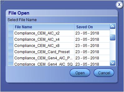
| Note:The setup files path is
C:\Program Files\Tektronix\TekExpress\TekExpress PCI Express\Setup Files
|
RF Switch configuration files
TekExpress PCI Express package contains RF Switch configuration files.
| File name | Configuration details |
|---|---|
|
PCE_Keithley_SYB_x6 |
Recall this file for Keithley S46T RF Switch and System-Board device type. The below are the configuration details:
|
|
PCE_KthCCD_SYB_x12 |
Recall this file for Keithley S46T RF Switch and System-Board device type. The below are the configuration details:
|
|
PCE_Giga_SYB_x8 |
Recall this file for Gigatronics ASCOR 8000 Series RF Switch and System-Board device type. The below are the configuration details:
|
|
PCE_GigCCD_SYB_x16 |
Recall this file for Gigatronics ASCOR 8000 Series RF Switch and System-Board device type. The below are the configuration details:
|
|
PCE_Keithley_AIC_x12 |
Recall this file for Keithley S46T RF Switch and Add-In-Card device type. The below are the configuration details:
|
|
PCE_Giga_AIC_x16 |
Recall this file for Gigatronics ASCOR 8000 Series RF Switch and Add-In-Card device type. The below are the configuration details:
|
How to run Base SRIS Tx Test Board tests
This document describes the procedure to run PCIe Base Spec Gen4/Gen5 SRIS Tx Test Board tests using TekExpress PCI Express.
Accessories required
- Gen4/Gen5 Base specification fixture
- SMA-SMP cables
- TCA-SMA 292D / TriMode probes
- AWG7002A or AWG7001A
Capture data signals at sampling rate of 100Gsps/200Gsps with 12.5 M record length. Ensure the PCIE_TX_Toggle_Patterns_v10.0.0.2.exe is installed on AWG-70K series and the recommended probes and real time oscilloscopes are used.
- In DUT panel, select Specification as BaseSpec and Device Type as SRIS Tx Test Board.
- If AWG70K is detected then the AWG Clock Setup check box will be enabled in the configuration panel. Click the Setup button next to AWG Clock Setup check box. This will bring up the SRIS configuration, with a selection to choose SSC on/Off.
- Based on the selections of the AWG Clock Setup check box, SSC on/Off selection and different combinations of AWG setup files will be loaded on the AWG. These combinations dictate if an external 100 MHz reference clock (with SSC on/Off) on Ch1 of the AWG will be transmitted. The following AWG files loaded as per configuration for Base specification (Device) and DUT Type SRIS Tx Test Board (Suite) for Gen4 and Gen5.
- Click Start and when the application prompts, power on the Gen4/Gen5 DUT. Ensure that the DUT transmits Gen4/Gen5 selected presets. Analysis will be done with SigTest.
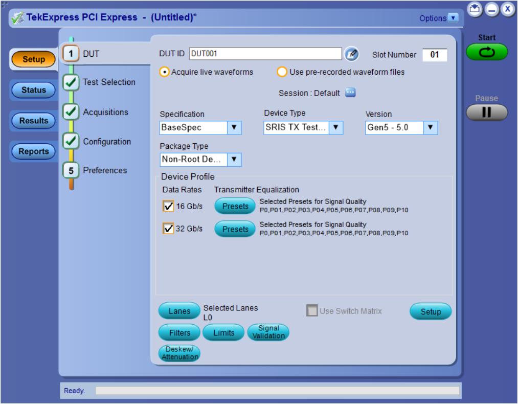
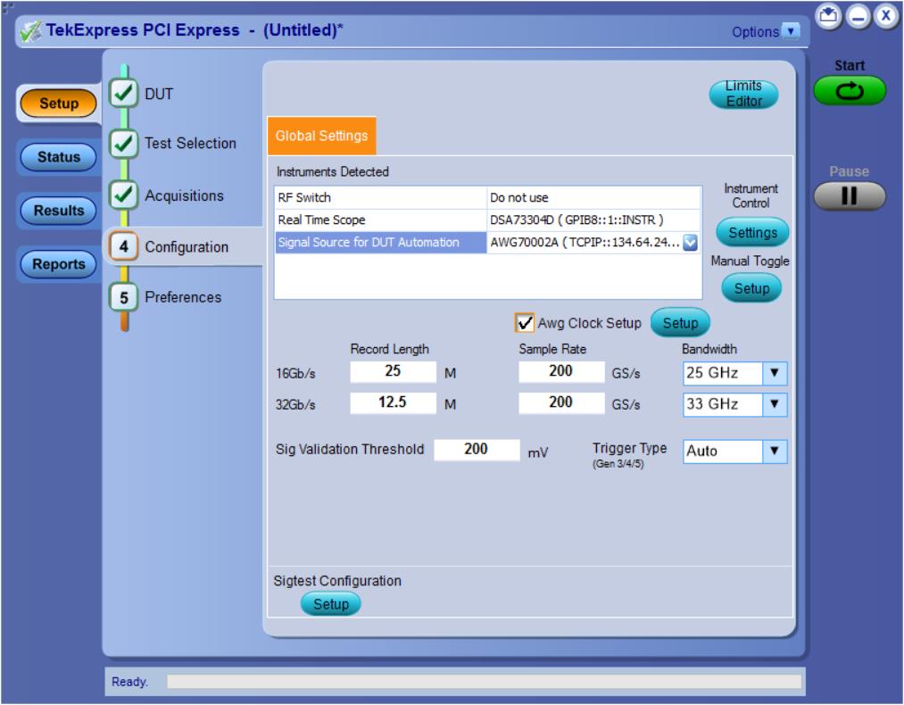
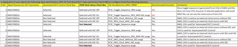
Help us improve our technical documentation. Provide feedback on our TekTalk documentation forum.