The RF pulse characteristics of a radar reveal a great deal about a its capability. Electronic Warfare (EW) and Electronic lntelligence (ELINT) experts specialize in the study of these pulsed signals. Pulse characteristics provide valuable information about the type of radar producing a signal and what its source might be; sailboat, battleship, passenger plane, bomber, missile, etc. But how do you find a radar pulse?
Steps to Finding the Radar Pulse
Before any measurements can be made, a measurement system must identify that a pulse exists and further locate some critical features of the pulse. Tektronix pulse measurement software uses several techniques to make sure a pulse never goes undetected.
- The Threshold Setting
Spectrum analyzers and other RF receivers often have dynamic range exceeding 100 dB, which gives visibility of very low-level signals, and low-level noise. The threshold setting prevents the detection algorithm from seeing the noise as pulses, as well as any overshoot, undershoot, and other pulse distortions. The threshold is usually specified in dBc relative to the pulse-top carrier amplitude. For a pulse to be detected, there must be an increase in the power level passing through the threshold level followed by a corresponding decrease in power level.
The actual detection of pulses can be complicated by variations in some of the pulse characteristics encountered in modern pulsed radars. The duty cycle may be very small, which leaves the pulse detector looking at only noise for most of the pulse interval. The pulse timing may also vary from pulse to pulse, or the frequency of each pulse may hop in an unpredictable sequence. Even the amplitude may vary between pulses.

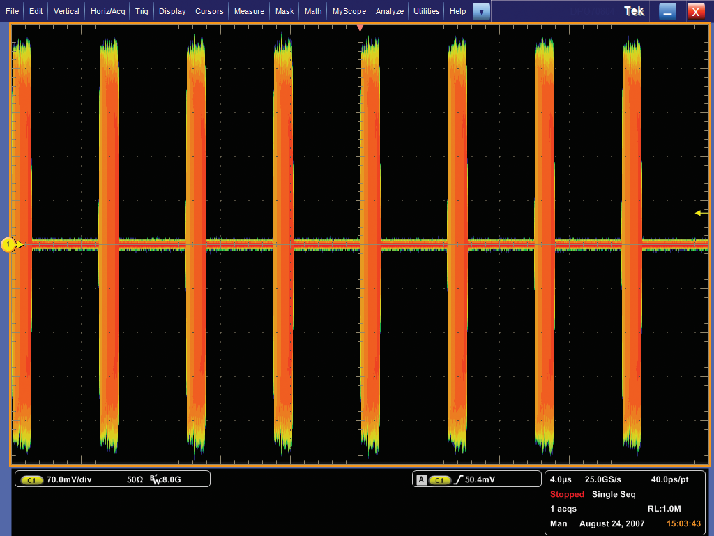
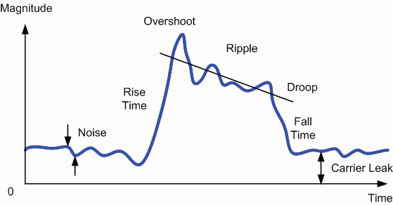
Figure 1. Real-world pulses are rarely clean.
Other pulse detection difficulties arise if the pulses exhibit real-world characteristics as shown in Figure 1. such as ringing, droop, carrier leakage, unequal rise and fall times, or amplitude variations such as a dip in the middle of a pulse.
The greatest difficulty is a poor signal-to-noise ratio (SNR). The bandwidth of a signal gets wider as a pulse width gets narrower, the rise time gets shorter, or a frequency chirp gets wider. The bandwidth of the measuring system must increase similarly. Of course, as the bandwidth increases, the overall measured noise increases and the possibility of measuring unintended spurious signals grows.
- Pulse Carrier Amplitude
The basic tradeoff in any pulse amplitude algorithm is between the reliability of the detection versus the speed of the algorithm. Even though the pulse measurements are generally an offline process (they only operate on data already stored in memory), you still want measurements to be fast.
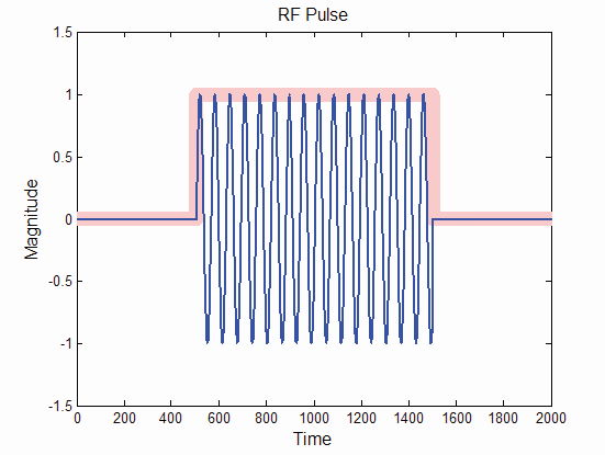
Most carrier-level detection algorithms use envelope detection. In envelope detection, a simple CW pulse is represented by a voltage waveform of a baseband pulse that modulates an RF carrier. The actual mechanism is to take the square root of the sum of the squares of the (I) and (Q) values at each digital sample of the intermediate frequency (IF) signal. In Figure 2, the blue trace illustrates an RF pulse. There are 16 complete cycles of the RF contained in this pulse. The pink trace is the complex envelope of the pulse.
Figure 2. The pink envelope is created off the blue RF signal. The envelope is then used for pulse detection.
Modern pulse analysis methods speed up the process of characterizing transmitter designs by taking advantage of the increased computing power of modern test and measurement instruments, with their ability to quickly crunch through multiple algorithms. For example, the method used by Tektronix equipment applies four separate algorithms to perform pulse detection. Each algorithm is loaded into the DSP engine of the instrument one at a time, with the simplest and fastest performed first. If a pulse is found at any step, the process ends as a pulse has been identified. This method ensures that a pulse is detected, and its amplitude is measured as quickly and accurately as possible.
- Locate the Pulse Cardinal Points
Once it has been determined that a pulse does exist, a model of the pulse will be constructed with four "cardinal points" and four lines as seen in Figure 3. These points and lines are the fundamentals from which all the measurements are referenced.
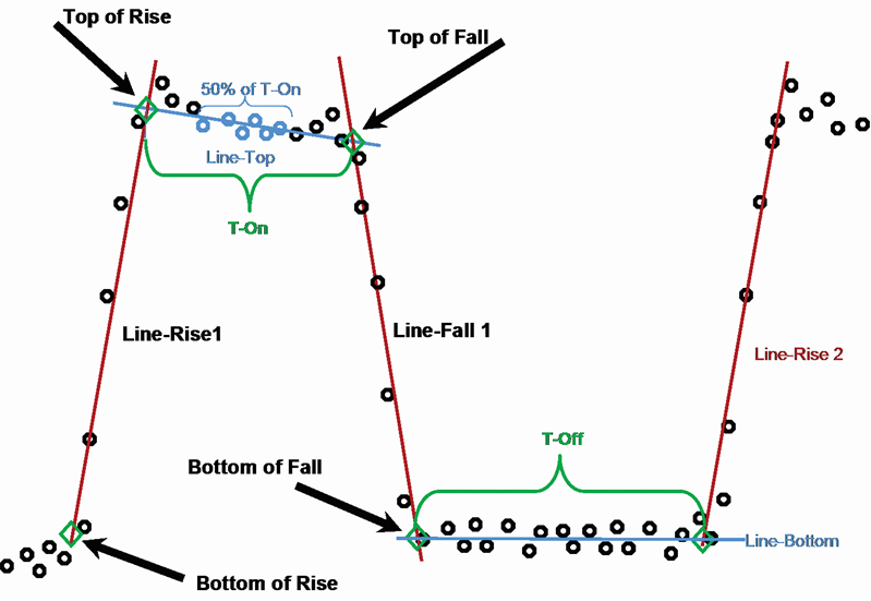
Figure 3. The cardinal points and connecting lines of the pulse model.
To construct the model, a re-iterative least-squares fit is done on the pulse points to determine the best-fit position for the lines. The process starts with the top line where a line-fit begins with only the center 50 percent of the points at the top. This is done to minimize errors from any overshoot or ringing at the transitions. This line-fit process can find the slope of the top line to analyze droop. Next, the same straight-line fit is performed on the rise time and the fall time. Then a baseline is calculated through the bottom points. Finally, the four points are located at the intersections of the lines. These points and lines describe the model of the pulse. From here, further measurement, analysis, and comparisons can take place.
As you can see, finding a radar pulse for automated measurements presents comes with a number of challenges. The transient nature of radar pulses combined with modern pulse compression schemes often demand carefully designed test setups. The particular methods discussed in this blog are used by Tektronix SignalVu-PC software’s Advanced Pulse Analysis add-in with either Spectrum Analyzers or time-domain oscilloscopes. To learn more about the methods of finding radar pulses, and the measurements you can make on them once found, download our primer on Fundamentals of Radar Measurements.