Kontaktaufnahme
Live-Chat mit Tektronix-Vertretern. Verfügbar von 9 bis 17 Uhr CET Geschäftstage.
Kontaktieren Sie uns telefonisch unter
Verfügbar von 9 bis 17 Uhr CET Geschäftstage.
Download
Laden Sie Handbücher, Datenblätter, Software und vieles mehr herunter:
Feedback
2 Series MSO Service Manual
This manual provides theory of operation, service instructions, and a list of replaceable parts for 2 Series MSO instruments.
Dieses Handbuch bezieht sich auf:
MSO22, MSO24, MSO22-EDU, MSO24-EDU
By downloading, you agree to the terms and conditions of the Manuals Download Agreement.Manuals Download Agreement
ATTENTION: please read the following terms and conditions carefully before downloading any documents from this website. By downloading manuals from Tektronix' website, you agree to the following terms and conditions:
Manuals for Products That Are Currently Supported:
Tektronix hereby grants permission and license to owners of Tektronix instruments to download and reproduce the manuals on this website for their own internal or personal use. Manuals for currently supported products may not be reproduced for distribution to others unless specifically authorized in writing by Tektronix, Inc.
A Tektronix manual may have been revised to reflect changes made to the product during its manufacturing life. Thus, different versions of a manual may exist for any given product. Care should be taken to ensure that one obtains the proper manual version for a specific product serial number.
Manuals for Products That Are No Longer Supported:
Tektronix cannot provide manuals for measurement products that are no longer eligible for long term support. Tektronix hereby grants permission and license for others to reproduce and distribute copies of any Tektronix measurement product manual, including user manuals, operator's manuals, service manuals, and the like, that (a) have a Tektronix Part Number and (b) are for a measurement product that is no longer supported by Tektronix.
A Tektronix manual may be revised to reflect changes made to the product during its manufacturing life. Thus, different versions of a manual may exist for any given product. Care should be taken to ensure that one obtains the proper manual version for a specific product serial number.
This permission and license does not apply to any manual or other publication that is still available from Tektronix, or to any manual or other publication for a video production product or a color printer product.
Disclaimer:
Tektronix does not warrant the accuracy or completeness of the information, text, graphics, schematics, parts lists, or other material contained within any measurement product manual or other publication that is not supplied by Tektronix or that is produced or distributed in accordance with the permission and license set forth above.
Tektronix may make changes to the content of this website or to its products at any time without notice.
Limitation of Liability:
TEKTRONIX SHALL NOT BE LIABLE FOR ANY DAMAGES WHATSOEVER (INCLUDING, WITHOUT LIMITATION, ANY CONSEQUENTIAL OR INCIDENTAL DAMAGES, DAMAGES FOR LOSS OF PROFITS, BUSINESS INTERRUPTION, OR FOR INFRINGEMENT OF INTELLECTUAL PROPERTY) ARISING OUT OF THE USE OF ANY MEASUREMENT PRODUCT MANUAL OR OTHER PUBLICATION PRODUCED OR DISTRIBUTED IN ACCORDANCE WITH THE PERMISSION AND LICENSE SET FORTH ABOVE.
Read Online
Important safety information
This manual contains information and warnings that must be followed by the user for safe operation and to keep the product in a safe condition.
General safety summary
Use the product only as specified. Review the following safety precautions to avoid injury and prevent damage to this product or any products connected to it. Carefully read all instructions. Retain these instructions for future reference.
This product shall be used in accordance with local and national codes.
For correct and safe operation of the product, it is essential that you follow generally accepted safety procedures in addition to the safety precautions specified in this manual.
The product is designed to be used by trained personnel only.
Only qualified personnel who are aware of the hazards involved should remove the cover for repair, maintenance, or adjustment.
Before use, always check the product with a known source to be sure it is operating correctly.
This product is not intended for detection of hazardous voltages.
Use personal protective equipment to prevent shock and arc blast injury where hazardous live conductors are exposed.
While using this product, you may need to access other parts of a larger system. Read the safety sections of the other component manuals for warnings and cautions related to operating the system.
When incorporating this equipment into a system, the safety of that system is the responsibility of the assembler of the system.
Service safety summary
The Service safety summary section contains additional information required to safely perform service on the product. Only qualified personnel should perform service procedures. Read this Service safety summary and the General safety summary before performing any service procedures.
To avoid electric shock
Do not touch exposed connections.
Do not service alone
Do not perform internal service or adjustments of this product unless another person capable of rendering first aid and resuscitation is present.
Disconnect power
To avoid electric shock, switch off the product power and disconnect the power cord from the mains power before removing any covers or panels, or opening the case for servicing.
Use care when servicing with power on
Dangerous voltages or currents may exist in this product. Disconnect power, remove battery (if applicable), and disconnect test leads before removing protective panels, soldering, or replacing components.
Verify safety after repair
Always recheck ground continuity and mains dielectric strength after performing a repair.
To avoid fire or personal injury
Use proper power cord
Use only the power cord specified for this product and certified for the country of use. Do not use the provided power cord for other products.
Ground the product
This product is grounded through the grounding conductor of the power cord. To avoid electric shock, the grounding conductor must be connected to earth ground. Before making connections to the input or output terminals of the product, ensure that the product is properly grounded. Do not disable the power cord grounding connection.
Power disconnect
The power cord disconnects the product from the power source. See instructions for the location. Do not position the equipment so that it is difficult to operate the power cord; it must remain accessible to the user at all times to allow for quick disconnection if needed.
Use proper AC adapter
Use only the AC adapter specified for this product.
Connect and disconnect properly
Do not connect or disconnect probes or test leads while they are connected to a voltage source.
Use only insulated voltage probes, test leads, and adapters supplied with the product, or indicated by Tektronix to be suitable for the product.
Observe all terminal ratings
To avoid fire or shock hazard, observe all rating and markings on the product. Consult the product manual for further ratings information before making connections to the product.
Do not exceed the Measurement Category (CAT) rating and voltage or current rating of the lowest rated individual component of a product, probe, or accessory. Use caution when using 1:1 test leads because the probe tip voltage is directly transmitted to the product.
Do not apply a potential to any terminal, including the common terminal, that exceeds the maximum rating of that terminal.
Do not float the common terminal above the rated voltage for that terminal.
The measurement terminals on this product are not rated for connection to Category III or IV circuits.
Do not connect a current probe to any wire that carries voltages above the current probe voltage rating.
Do not operate without covers
Do not operate this product with covers or panels removed, or with the case open. Hazardous voltage exposure is possible.
Avoid exposed circuitry
Do not touch exposed connections and components when power is present.
Do not operate with suspected failures
If you suspect that there is damage to this product, have it inspected by qualified service personnel.
Disable the product if it is damaged. Do not use the product if it is damaged or operates incorrectly. If in doubt about safety of the product, turn it off and disconnect the power cord. Clearly mark the product to prevent its further operation.
Before use, inspect voltage probes, test leads, and accessories for mechanical damage and replace when damaged. Do not use probes or test leads if they are damaged, if there is exposed metal, or if a wear indicator shows.
Examine the exterior of the product before you use it. Look for cracks or missing pieces.
Use only specified replacement parts.
Replace batteries properly
Replace batteries only with the specified type and rating.
Recharge batteries for the recommended charge cycle only.
Wear eye protection
Wear eye protection if exposure to high-intensity rays or laser radiation exists.
Do not operate in wet/damp conditions
Be aware that condensation may occur if a unit is moved from a cold to a warm environment.
Do not operate in an explosive atmosphere
Keep product surfaces clean and dry
Remove the input signals before you clean the product.
Provide proper ventilation
Refer to the installation instructions in the manual for details on installing the product so it has proper ventilation.
Slots and openings are provided for ventilation and should never be covered or otherwise obstructed. Do not push objects into any of the openings.
Provide a safe working environment
Always place the product in a location convenient for viewing the display and indicators.
Avoid improper or prolonged use of keyboards, pointers, and button pads. Improper or prolonged keyboard or pointer use may result in serious injury.
Be sure your work area meets applicable ergonomic standards. Consult with an ergonomics professional to avoid stress injuries.
Use only the Tektronix rackmount hardware specified for this product.
Probes and test leads
Before connecting probes or test leads, connect the power cord from the power connector to a properly grounded power outlet.
Keep fingers behind the protective barrier, protective finger guard, or tactile indicator on the probes. Remove all probes, test leads and accessories that are not in use.
Use only correct Measurement Category (CAT), voltage, temperature, altitude, and amperage rated probes, test leads, and adapters for any measurement.
Beware of high voltages
Understand the voltage ratings for the probe you are using and do not exceed those ratings. Two ratings are important to know and understand:
- The maximum measurement voltage from the probe tip to the probe reference lead.
- The maximum floating voltage from the probe reference lead to earth ground.
These two voltage ratings depend on the probe and your application. Refer to the Specifications section of the manual for more information.
 | WARNING:To prevent electrical shock, do not exceed the maximum measurement or maximum floating voltage for the oscilloscope input BNC connector, probe tip, or probe reference lead. |
Connect and disconnect properly.
Connect the probe output to the measurement product before connecting the probe to the circuit under test. Connect the probe reference lead to the circuit under test before connecting the probe input. Disconnect the probe input and the probe reference lead from the circuit under test before disconnecting the probe from the measurement product.
De-energize the circuit under test before connecting or disconnecting the current probe.
Connect the probe reference lead to earth ground only.
Ground-referenced oscilloscope use
Do not float the reference lead of the probe when using with ground-referenced oscilloscopes. The reference lead must be connected to earth potential (0 V).
Floating measurement use
Do not float the reference lead of the probe above the rated float voltage.
Terms in this manual and on the product
These terms may appear in this manual:
| WARNING:Warning statements identify conditions or practices that could result in injury or loss of life. |
| CAUTION:Caution statements identify conditions or practices that could result in damage to this product or other property. |
These terms may appear on the product:
- DANGER indicates an injury hazard immediately accessible as you read the marking.
- WARNING indicates an injury hazard not immediately accessible as you read the marking.
- CAUTION indicates a hazard to property including the product.
Symbols on the product
 | When this symbol is marked on the product, be sure to consult the manual to find out the nature of the potential hazards and any actions which have to be taken to avoid them. (This symbol may also be used to refer the user to ratings in the manual.) |
The following symbols(s) may appear on the product.
 CAUTION: Refer to Manual |  Protective Ground (Earth) Terminal |  Earth Terminal |  Chassis Ground |  WARNING: High Voltage |  Connection and disconnection to hazardous bare wire permitted. |
 Standby |  Functional Earth Terminal |  Use only on an insulated wire. |  Breakable. Do not drop. |  Do not connect to or remove from an uninsulated conductor that is HAZARDOUS LIVE. | |
Operating safely with battery power
For safe operation, the instrument chassis should always remain at earth ground potential.
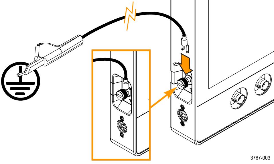
| WARNING:To avoid electric shock, always use the Tektronix-provided grounding cable when the oscilloscope is operating on battery power and not connected to the external power supply. The Tektronix-provided grounding cable is not for permanent usage. |
Without a connection between the chassis and earth ground, you may receive a shock from exposed metal on the chassis if you connect an input to a hazardous voltage (>30 VRMS, >42 Vpk). To protect yourself against possible shock, attach the Tektronix-provided grounding cable.
The grounding cable is necessary to provide protective bonding between the oscilloscope and a dedicated earthing terminal, in accordance with the NEC, CEC, and local codes. Consider having a qualified electrician to approve the installation.
The grounding cable shall be connected before powering on the oscilloscope and before attaching the probes to any circuit. Connect the grounding cable from the ground lug terminal on the side panel of the instrument to a dedicated earthing terminal. Make sure the teeth of the alligator clip makes good electrical contact and is secured against slipping.
The alligator clip on the grounding cable must be connected to a dedicated earthing terminal, an earthing terminal bar, or identified equipment grounding points (a rack cabinet for example). Make sure you have a good electrical connection to an appropriate grounding device that is identified with a Protective Earth symbol, or the word GROUND/GND, or the color green (green ground screw/conductor). If none of these are present, assume the connection is not earthed.
Always verify that the grounding cable is making good electrical contact by using an ohmmeter or continuity meter between the dedicated earthing terminal and the ground lug terminal on the side panel of the oscilloscope. Verify again anytime the oscilloscope has been left unattended.
Make sure the dedicated earthing terminal is located in close proximity to the circuit under test. Keep the grounding cable clear of heat sources and mechanical hazards such as; sharp edges, screw threads, moving parts, and closing doors/covers. Inspect the cable, insulation, and terminal ends for damage before use. Do not use a damaged grounding cable. Contact Tektronix for a replacement.
If you choose not to attach the grounding cable, you are not protected against electric shock if you connect the oscilloscope to a hazardous voltage. You can still use the oscilloscope if you do not connect a signal greater than 30 VRMS (42 Vpk) to the probe tip, the BNC connector center, or the common lead. Make sure all probe common leads are connected to the same voltage.
| WARNING:Hazardous voltages may exist in unexpected places due to faulty circuitry in the device under test. |
| CAUTION:When operating the instrument on battery power do not connect a grounded device, such as a printer or computer, to the oscilloscope unless the instrument grounding cable is connected to the earth ground. |
Preface
Information to help service your instrument.
Read the General and Service safety summaries before servicing the product.
Be sure to read the introductions to all procedures. These introductions provide important information needed to perform the service correctly, safely, and efficiently.
Supported products
This manual contains information that is necessary to service all 2 Series MSO instruments.
Check for a specific product designation in the header at the top of the page, in a heading, table or figure title, or within text. Material that does not have any specific product designation applies to all products in the manual.
Where to find operating information
For information on installing, operating, and networking the instrument, refer to the online help or user manual that was provided with your oscilloscope.
You can also find the manual at http://www.tek.com/manuals by searching for your product.
Theory of operation
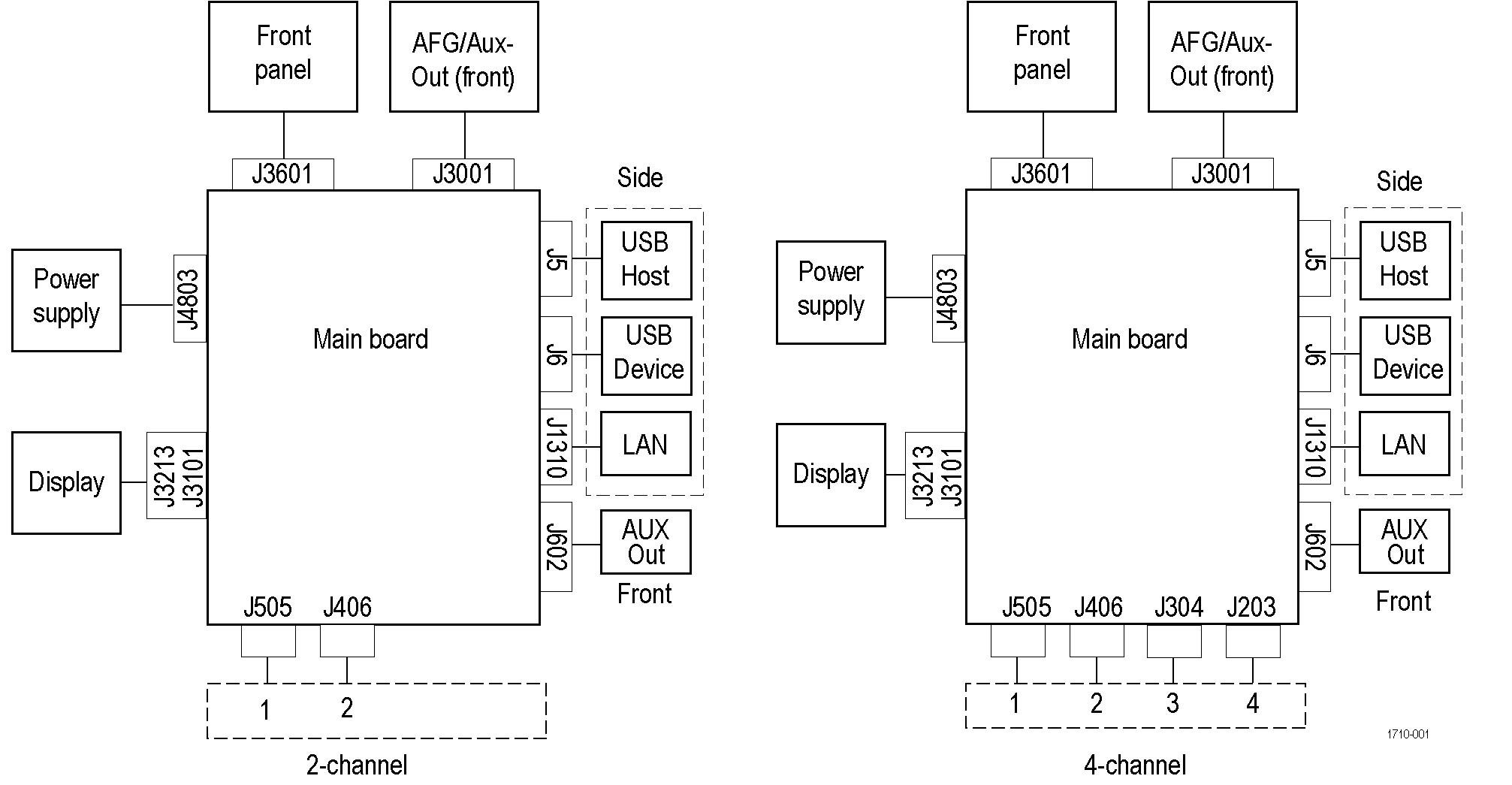
This section describes the electrical operation of the oscilloscope to the module level. The block diagram shows the oscilloscope module interconnections.
Power supply
The external AC/DC power supply converts AC line voltage to +24 VDC to power the instrument.
Main board
The Main boards contain the following functions:
Acquisition system
The acquisition system begins with the analog signal path and ends with a digitized signal in memory. The signal enters a channel input, and then passes through an attenuator and preamplifier. The analog signal from each preamplifier goes through a digitizer, and then into acquisition memory. The analog signal from each preamplifier is also distributed to a trigger circuit.
Trigger system
The trigger system digitizes the analog signals from the preamplifiers and routes the digitized signal to the trigger circuit. Advanced trigger functions are enabled only when the appropriate application modules and supporting software are installed.
Processor system
The processor system contains an ARM microprocessor that controls the entire instrument. The processor system also contains FLASH ROM, system RAM, and interfaces to USB ports and the ethernet port.
Front panel and display
The front panel circuit contains digital logic that reads the front panel buttons and sends this information to the processor system on the main board. The front panel circuit also contains indicator LEDs to represent system status to the user.
Maintenance
Preventing ESD
Before servicing this product, read the General Safety Summary and the Service Safety Summary at the front of the manual, as well as the following ESD information.
| CAUTION:Electrostatic discharge (ESD) can damage any semiconductor component in this instrument.
|
When performing any service that requires internal access to the instrument, adhere to the following precautions to avoid damaging internal modules and their components due to electrostatic discharge:
-
Minimize handling of static-sensitive circuit boards and components.
-
Transport and store static-sensitive modules in their static protected containers or on a metal rail. Label any package that contains static-sensitive boards.
-
Discharge the static voltage from your body by wearing a grounded antistatic wrist strap while handling these modules.
-
Service static-sensitive modules only at a static-free work station.
-
Do not allow any items capable of generating or holding a static charge on the work station surface.
-
Handle circuit boards by the edges when possible.
-
Do not slide the circuit boards over any surface.
-
Avoid handling circuit boards in areas that have a floor or work-surface covering capable of generating a static charge.
Inspection and cleaning
This section describes how to inspect for dirt and damage. It also describes how to clean the exterior and interior of the instrument. Inspection and cleaning are done as preventive maintenance. Preventive maintenance, when done regularly, may prevent instrument malfunction and enhance its reliability.
Preventive maintenance consists of visually inspecting and cleaning the instrument and using general care when operating it.
How often to perform maintenance depends on the severity of the environment in which the instrument is used. A proper time to perform preventive maintenance is just before instrument adjustment.
Exterior cleaning (other than display)
Clean the exterior surfaces of the chassis with a dry lint-free cloth or a soft-bristle brush. If any dirt remains, use a cloth or swab dipped in a 75% isopropyl alcohol solution. Use a swab to clean narrow spaces around controls and connectors. Do not use abrasive compounds on any part of the chassis that may damage the chassis.
Clean the On/Standby switch using a cleaning towel dampened with deionized water. Do not spray or wet the switch itself.
| CAUTION:Avoid the use of chemical cleaning agents which might damage the plastics used in this instrument. Use only deionized water when cleaning the front-panel buttons. Use a 75% isopropyl alcohol solution as a cleaner for cabinet parts. Before using any other type of cleaner, consult your Tektronix Service Center or representative.
|
Inspect the outside of the instrument for damage, wear, and missing parts. Immediately repair defects that could cause personal injury or lead to further damage to the instrument.
| Item | Inspect for | Repair action |
|---|---|---|
| Cabinet, front panel, and cover | Cracks, scratches, deformations, damaged hardware | Repair or replace defective module |
| Front-panel knobs | Missing, damaged, or loose knobs | Repair or replace missing or defective knobs |
| Connectors | Broken shells, cracked insulation, and deformed contacts. Dirt in connectors | Repair or replace defective modules. Clear or brush out dirt |
| Carrying handle and cabinet feet | Correct operation | Repair or replace defective module |
| Accessories | Missing items or parts of items, bent pins, broken or frayed cables, and damaged connectors | Repair or replace damaged or missing items, frayed cables, and defective modules |
Flat panel display cleaning
Clean the flat panel display surface by gently rubbing the display with a clean-room wipe (such as Wypall Medium Duty Wipes, #05701, available from Kimberly-Clark Corporation), or an abrasive-free cleaning cloth.
If the display is very dirty, moisten the wipe or cloth with distilled water, a 75% isopropyl alcohol solution, or standard glass cleaner, and gently rub the display surface. Use only enough liquid to dampen the cloth or wipe. Avoid using excess force or you may damage the display surface.
| CAUTION:Improper cleaning agents or methods can damage the flat panel display.
|
| CAUTION:To prevent getting moisture inside the instrument during external cleaning, do not spray any cleaning solutions directly onto the screen or instrument.
|
Remove and replace procedures
This section contains procedures for removal and installation of replaceable modules in the instrument. Refer to Replaceable parts for lists and exploded views of replaceable modules.
Any module inside of the chassis that does not have a remove and replace procedure requires that the entire instrument be returned to Tektronix Service Center for service.
| WARNING: Before performing this or any other procedure in this manual, read the safety summaries found at the beginning of this manual. Also, to prevent possible injury to service personnel or damage to the instrument components, read Preventing ESD. Before performing any procedure in this subsection, disconnect the power cord from the line voltage source. Failure to do so could cause serious injury or death. |
| Note:Read the cleaning procedure before disassembling the instrument for cleaning. |
Required equipment
Most assemblies in this instrument can be removed with a T-10 Torx® screwdriver tip.
| Item No. | Name | Description |
|---|---|---|
| 1 | Screwdriver handle | Accepts Torx-driver bits |
| 2 | T-10 Torx tip | Used for removing instrument screws. Torx-driver bit for T-10 size screw heads |
| 3 | T-8 Torx tip | Used for removing screws securing the internal power cable |
| 4 | Instrument Assembly Fixture | Used to hold the instrument in place during service |
| 5 | Metal Instrument Stand | Used to mount the instrument in a specific position |
Remove front panel knobs
Use this procedure to remove and replace front panel knob assemblies.
Before you begin
Procedure
- To remove a knob assembly, pull the knob straight out of the front panel. Finger strength is adequate to pull knobs. Do not use pliers.
- To reinstall a knob, align the knob with the shaft indent and press the knob onto the shaft. Turn the knob to make sure there is a smooth rotation.
Disassemble instrument
Use this procedure to disassemble the instrument and to replace the parts.
Before you begin
Procedure
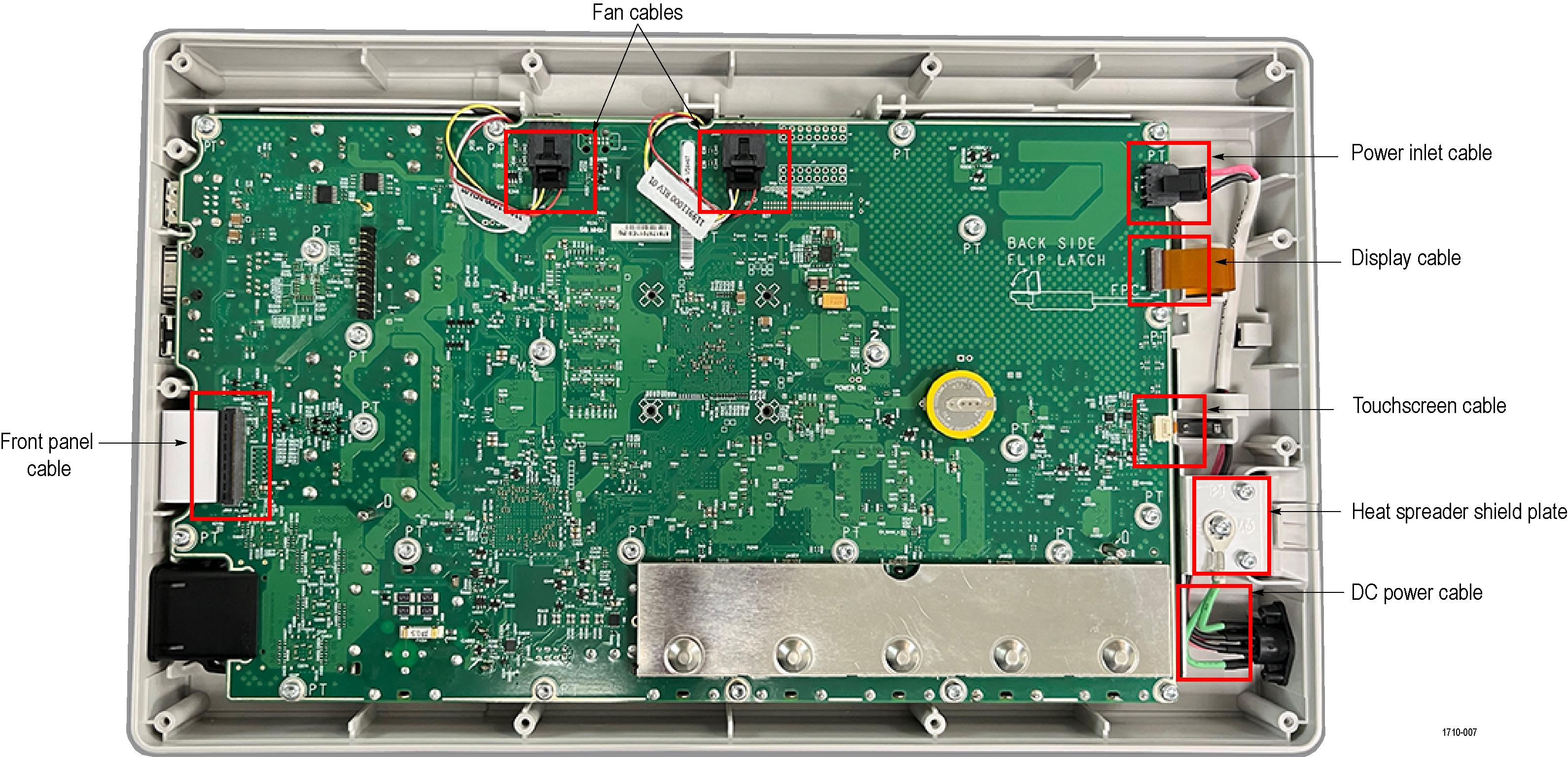
- Remove the main board.
- To remove the front panel cable, flip up the front side of the connector latch and lift the flex cable up and away from the board.
- To remove the two fan cables, depress the latch and slide the cable away from the connector.
- To remove the power inlet cable, depress the latch and slide the cable away from the connector.
- To remove the display cable, flip up the connector latch on back side (away from cable) and slide the flex cable out of the connector.
- To remove the touchscreen cable, flip up the front side of the connector latch and slide the flex cable out of the connector.
- Remove the two T-10 Torx screws near the center of the board marked "M3". These metal screws are unique, keep them separated from the rest of the removed screws.
- Remove the remaining twenty-two T-10 Torx screws from the board.
- Remove the main board.
- To reinstall, reverse the steps. Tighten all T-10 Torx screws to 0.65 N·m when reinstalling. Reconnect all the cable to the connectors.

Troubleshooting
Before performing this or any other procedure in this manual, read the General Safety Summary and Service Safety Summary found at the beginning of this manual.
To prevent possible injury to service personnel or damage to electrical components, please read information on Preventing ESD. (See Preventing ESD)
This section contains information and procedures designed to help you isolate faults to a module and requires that service personnel have the appropriate skills to work on this instrument, including PC troubleshooting and Microsoft Windows operating system skills. Details of PC and Windows operation and service are not in this manual.
For assistance, contact your local Tektronix Service Center.
Service level
This subsection contains information and procedures to help you determine if a faulty power supply is the problem with your instrument. If replacing the power supply does not fix the fault, you will need to return the instrument to a Tektronix Service Center for repair, as no other internal electronic assemblies or modules are user-replaceable.
Check for common problems
Use the following table to help isolate possible failures.
The table lists problems and possible causes. The list is not comprehensive, but it may help you eliminate a problem that is quick to fix, such as a loose power cord. For more detailed troubleshooting, see the Troubleshooting procedures.
| Symptom | Possible cause(s) |
|---|---|
| Power on, but the instrument will not boot | Power on configuration |
| Clock Tree | |
| Board ID | |
| Serial bus issues | |
| Black display | Bad display |
| Bad cable | |
| Board level connectivity | |
| Black screen detect circuit | |
| Display flicker | Bad display |
| Bad cable | |
| Board level connectivity | |
| Black screen detect circuit | |
| Cannot set time/date | RTC device |
| I2C Bus issues | |
| Touch screen not working | I2C Bus issues |
| Interrupt or Reset issues | |
| Bad cable | |
| Bad touch sensor | |
| License keys will not load | Bad encryption EEPROM |
| Instrument will not power on | Power enable |
| Power supplies | |
| Instrument will not power off properly | MFG JTAG connection |
| Processor/Power control communication | |
| Button press logic | |
| Power on momentarily then off | Power enable |
| Power supplies | |
| Instrument will not remember previous power state | Power enable |
| No battery communication | PMBus isolator |
| No ethernet | Ethernet phy |
| Power on and boots, but no serial console | Serial buffers |
| DPG not functional | Not a failure |
| Serial present detect | |
| Fan speed abnormal | Fan Tach logic |
| Fan control | |
| USB device port not functional | 26 MHz generator |
| USB receiver | |
| USB host port not functional | 26 MHz generator |
| USB phy | |
| USB hub | |
| USB power | |
| Digital calibration failure | Digital threshold circuitry |
| Digital comparator circuitry | |
| Power drops when battery attached | Main board battery circuit |
| Front panel button issues | Flex circuit |
| Shift logic | |
| Front panel LED issues | Flex circuit |
| Shift logic | |
| Encoder problem | Encoder hardware |
| Encoder control |
Troubleshooting procedures
Use the following diagrams to troubleshoot an instrument failure. Begin with the Primary troubleshooting procedure.
- Use a digital voltmeter to check power supply voltages.
- Ensure an antistatic work environment. To prevent electrostatic damage to components whenever you work on the instrument, wear properly-grounded electrostatic prevention wrist and foot straps, and work in a tested antistatic environment on an antistatic mat.
| WARNING:Before removing the rear case, disconnect the power cord from the line voltage source. Failure to do so could cause serious injury or death. |
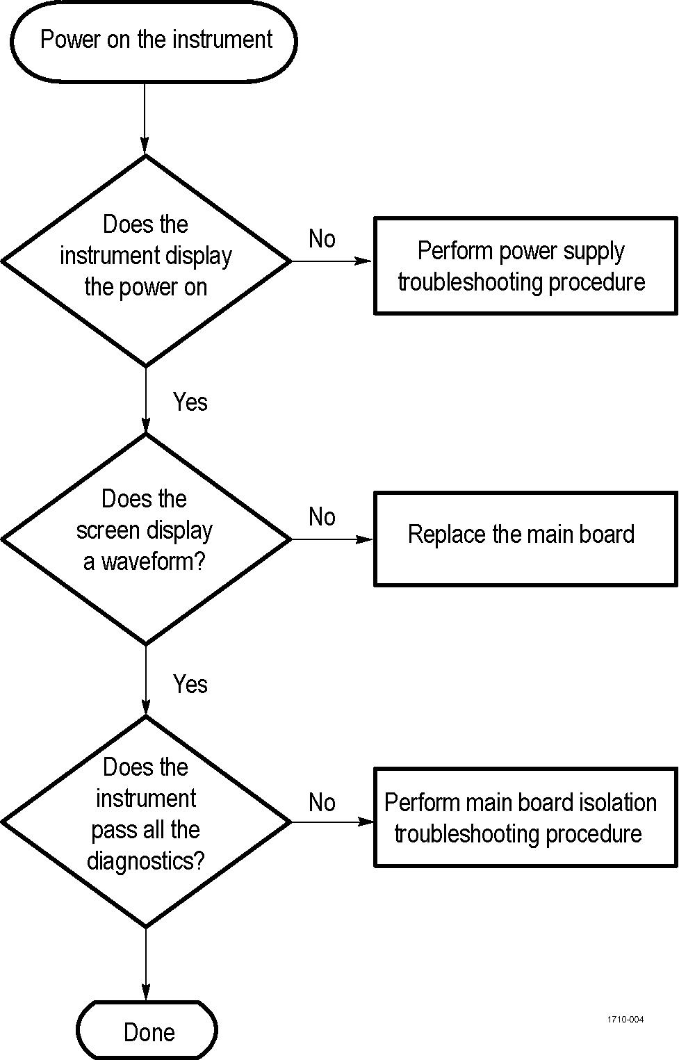
Primary troubleshooting procedure
Power supply troubleshooting procedure
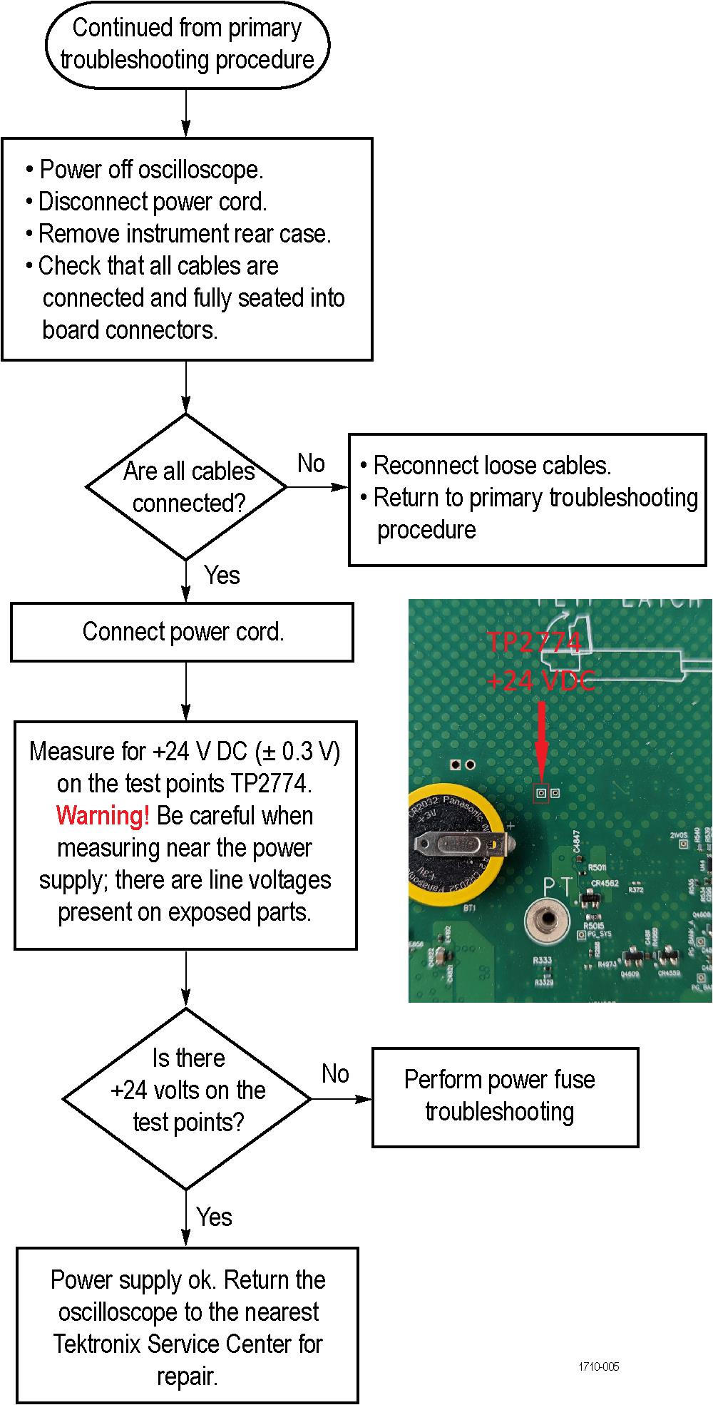
| Note:Images show the power supply cable disconnected from the main board, to better show the test point locations. The power cable from the power supply must be connected to the main board to test the +24 VDC value. |
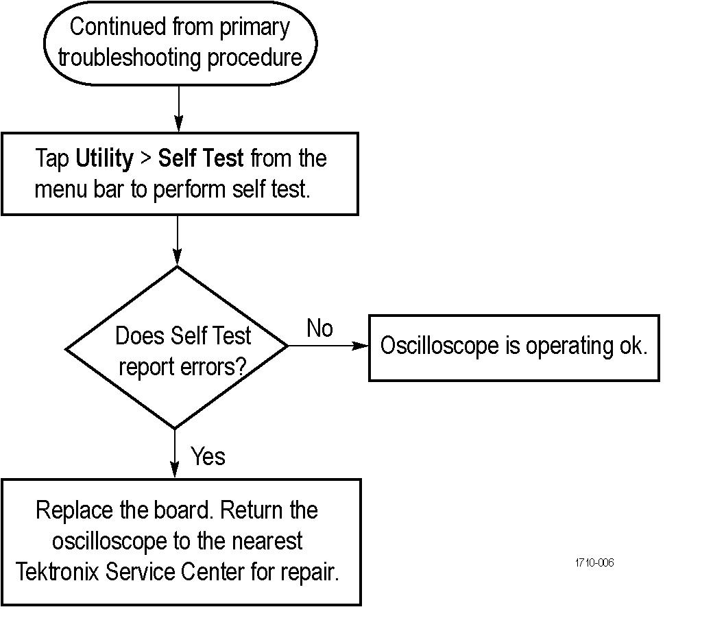
Main board isolation troubleshooting procedure
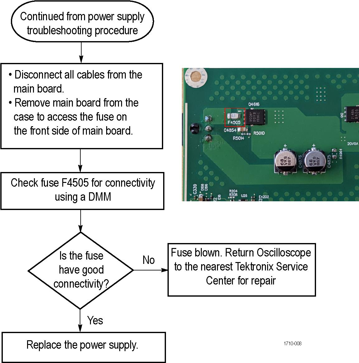
Power fuse troubleshooting procedure
Instrument self tests
The instrument runs self test diagnostics during every power on. The power on self tests ensure that the hardware and software are functionally working. The tests provide limited diagnostic information, and provide no performance information.
If the instrument detects errors during power on, a pop-up message indicates that a failure has occurred. To display the self test menu and results, select Utility > Self Test. Select a test mode and run the self tests. If you continue to get errors on one or more tests, you will need to return the instrument to your nearest Tektronix Service Center for repair.
Adjustment procedures and interval
Adjustment and calibration can be performed only by a Tektronix Service Center.
The voltage and timing references inside the instrument are very stable over time and do not need routine adjustment.
If the instrument fails the performance tests in the specifications and performance verification manual, adjustment may be required. To download the manual, go to tek.com, enter the instrument model number in the search field. The specification and performance verification document is listed under manuals.
If periodic calibration is required, a general rule is to verify performance and make adjustments (only if needed) every 2000 hours of operation or once a year if the instrument is used infrequently.
Adjustment after repair
After removal and replacement of any module, you must complete the performance verification procedures, found in the specifications and performance verification manual.
Replacement of the 2 Series MSO main board, front panel assembly or chassis requires adjustment and completion of the performance verification procedures.
Replaceable parts
Use the replaceable parts diagram and table to identify replaceable parts for your product.
You cannot order internal parts for the 2 Series MSO. For more information about replacing parts, contact your local Tektronix Service Center. Include the following information when contacting Tektronix.
- Part number
- Instrument type or model number
- Instrument serial number
- Instrument modification number, if applicable
Abbreviations conform to the American National Standard ANSI Y1.1-1972.
Returning instrument for service
Use the following instructions for returning your instrument for service.
When repacking the instrument for shipment, use the original packaging. If the packaging is not available or unfit for use, contact your local Tektronix representative to obtain new packaging.
If you need to return your instrument for repair or calibration, call 1-800-438-8165 or complete the form at tek.com/services/repair/rma-request. When you request service, have the serial number, firmware, and software version of the instrument.
If you want to see the warranty or service agreements on your products, or if you want to create your own service price estimate, visit our quick service quote site at tek.com/service-quote.
Full assembly parts list
Use the parts list table to identify mechanical and electrical components.
| Column name | Description |
|---|---|
| Index number | Items in this section are referenced by figure and index numbers to the exploded view illustrations that follow. |
| Tektronix part number | Use this part number when referencing parts from Tektronix. |
| Qty | This indicates the quantity of parts used. |
| Name and description | An item name is separated from the description by a colon (:). Because of space limitations, an item name may sometimes appear as incomplete. Use the US Federal Catalog handbook H6-1 for further item name identification. |
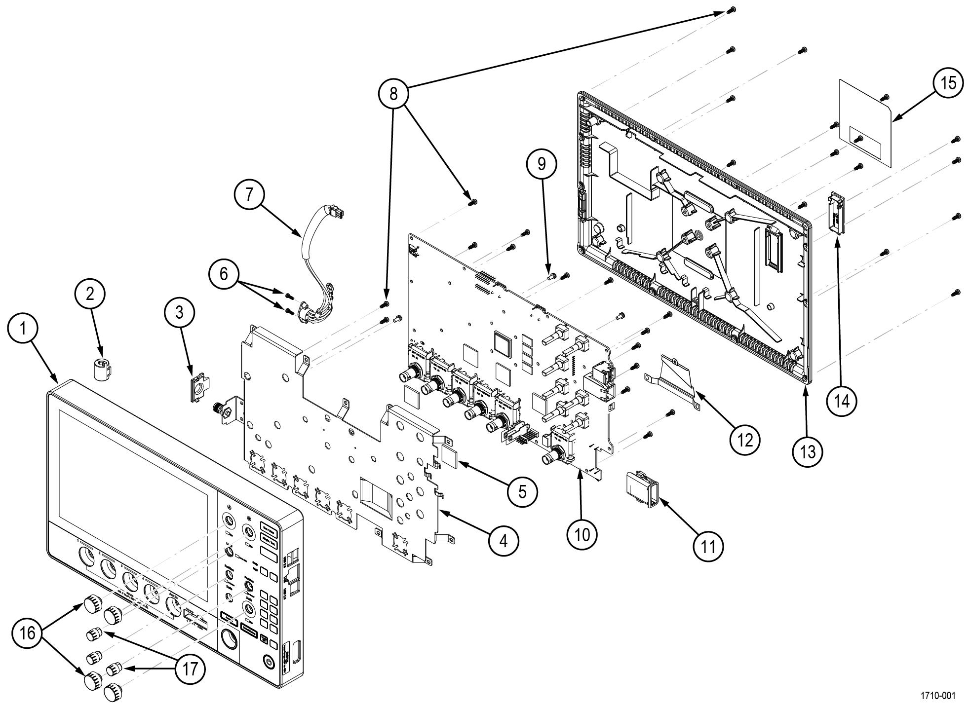
| Index number | Tektronix part number | Qty | Name and description |
|---|---|---|---|
| 1 | 065-1087-XX | 1 | SERVICE REPLACEMENT KIT; FRONT PANEL & CHASSIS FOR MSO22 |
| 065-1086-XX | 1 | SERVICE REPLACEMENT KIT; FRONT PANEL & CHASSIS FOR MSO24 | |
| 2 | 276-0894-XX | 1 | EMI SUPPRESSION; BROADBAND FERRITE; SPLIT ROUND CABLE, PKG APROX 15X15X18MML, IMPEDANCE 123 OHMS AT 100MHZ Also included in the Front Panel Service Replacement Kit |
| 3 | 200-5547-XX | 1 | HOUSING, GROUND LUG |
| 4 | 407-6225-XX | 1 | PLATE, MAIN HEAT SPREADER & EMI SHEILD |
| 5 | 342-1321-XX | 2 | THERMAL INTERFACE MATERIAL 20MM SQUARE, 2MM THICK |
| 6 | 211-1721-XX | 2 | SCREW, DELTA-PT, M2.5 X 8MM, T8 |
| 7 | 174-7435-XX | 1 | DC POWER CABLE ASSEMBLY |
| 8 | 211-1585-XX | 40 | SCREW, DELTA-PT, 3MM X 8MM, T10 |
| 9 | 211-1584-XX | 3 | SCREW, MACHINE, M3 X 0.5 X 6MM PAN HEAD, TORX T10 |
| 10 | 878-1798-XX | 1 | CIRCUIT BOARD ASSEMBLY; BUILD OPTION A; MAIN; 2 CH; 2 SERIES; 3895547XX; MSO22 |
| 878-1797-XX | 1 | CIRCUIT BOARD ASSEMBLY; STANDARD; MAIN; 4 CH; 2 SERIES; 3895547XX; MSO24 | |
| 11 | 351-1162-XX | 1 | GUIDE, MSO GUIDE |
| 12 | 337-4908-XX | 1 | SHIELD, BACKSIDE AFG |
| 337-4909-XX | 1 | INSULATOR, BACKSIDE AFG SHIELD | |
| 13 | 202-0592-XX | 1 | CASE, REAR |
| 14 | 200-5543-XX | 1 | COVER, BATTERY INTERFACE DOOR |
| 15 | 335-4466-XX | 1 | LABEL, REAR |
| 16 | 366-0968-XX | 4 | ASSEMBLY, KNOB WITH SPRING, MEDIUM |
| 17 | 366-0969-XX | 3 | ASSEMBLY, KNOB WITH SPRING, SMALL |
Help us improve our technical documentation. Provide feedback on our TekTalk documentation forum.