Introduction
Higher vertical resolution has long been a goal of oscilloscope designers, driven by the needs of engineers to measure finer detail on signals. However, delivering additional resolution means more than adding bits to the analog-to-digital converter (ADC) of the oscilloscope. The 4, 5 and 6 Series oscilloscopes include a new 12-bit ADC and two new low noise amplifiers that deliver not only theoretical resolution, but useful resolution. These revolutionary products also enable visualization of this higher resolution with a high definition display and fast update rate. This white paper describes an approach in which ADC resolution, combined with digital signal processing and a low-noise front end can provide even higher resolution than found in conventional high bit-rate ADC implementations.
This paper focuses on techniques designers of the Tektronix 4, 5 and 6 Series MSOs used to achieve higher-resolution acquisition details. It also describes the specification of Effective Number of Bits (ENOB) and how this important measure of system performance is properly applied as well as its limitations. For more information on multi-acquisition techniques such as waveform averaging, and more detail on ENOB, please see the references at the end of this paper.
The Quest for More Vertical Resolution
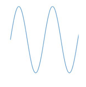
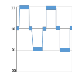
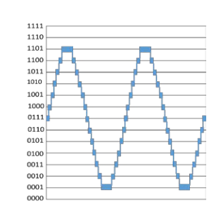
When a digital oscilloscope samples a signal, the ADC divides the signal into vertical bins (sometimes called digitizing levels or quantization levels or least significant bit (LSB)). Each bin represents a discrete vertical voltage level, and more bins mean more resolution. These digitizing levels in an ADC are represented as 2𝑁 where N represents the number of bits. A generic sine wave (Figure 2a) can look very different based on the vertical resolution. Figure 2b shows the sine wave digitized with a 2-bit ADC for 22 = 4 digitizing levels. Data could be stored in 4 different vertical bins: 00, 01, 10, or 11. A 4-bit ADC would have 16 digitizing levels and would be stored as 4-bit data (Figure 2c). Thus, the more digitizing levels, the higher the resolution, and the closer we are to representing the original analog signal in a digital oscilloscope.
Higher vertical resolution provides two important advantages:
- Clear visualization with the ability to “zoom” in on signals and see minute details
- It enables more precise measurements of voltage – particularly critical in power design validation
Traditional digital oscilloscopes have been built on 8-bit ADC technology, with much engineering effort going into increasing sample rate, thus improving horizontal resolution. Over time, 8-bit ADCs have been optimized for sample rate, noise performance, and low distortion. But the ADC on its own, provides 28 = 256 vertical digitizing levels which can be too coarse for applications like power design which demand higher vertical resolution.
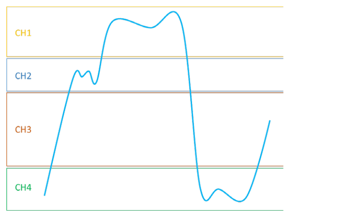
Working with 8-bit ADCs, a common approach to seeing more voltage detail is to overdrive multiple channels. In this approach, multiple channels are connected to the same signal and the voltage scales are set to intentionally overdrive the oscilloscope inputs. The vertical positions of each channel are adjusted to look at different parts of the signal. The user then “stiches” the signals back together in order to get increased vertical resolution This approach, illustrated in Figure 3, can introduce distortion as the 8- bit oscilloscope’s input amplifiers may struggle to recover from being overdriven. Test results are generally not guaranteed when an instrument is operated in this way.
New Oscilloscope ASICs Enable Higher Vertical Resolution
Advancements in oscilloscope acquisition system technology have enabled much higher vertical resolution than seen in previous 8-bit ADC acquisition systems. Much of this has been accomplished through carefully planned ASIC design implementations in oscilloscopes. In this white paper, we will illustrate how much improvement in higher resolution can be achieved through ASICs that deliver:
- Higher performance ADC (12-bit)
- HD display processing techniques
- Improved low noise, high gain analog front end
- Hardware filters to eliminate inherent noise
- Enabling high resolution triggering
Higher performance ADC (12-bit)
For example, in the Tektronix 4, 5 and 6 Series MSO oscilloscopes, there are a series of new ASICs that play key enablement roles. First is the analog-to-digital converter (ADC).
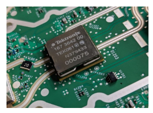
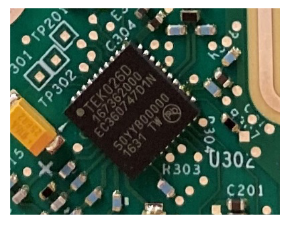
With a completely new ASIC (TEK049) providing four 12-bit successive approximation ADCs (Figure 4a). the TEK049 ADC runs at 25 GS/s and there can be one or two ASICs per 4, 5 or 6 Series MSO, depending upon channel count.
Since the ADCs built into the TEK049 ASIC are 12-bit, they provide 4,096 vertical digitizing levels, which is 16x more vertical resolution than previous 8-bit ADCs. In the 4 and 5 Series MSOs, they deliver finished 12-bit samples at 3.125 GS/s. At 6.25 GS/s the data is acquired through the 12-bit ADC but are stored in 8-bits of storage memory to accommodate the maximum transfer rate between the ASIC and memory. In the 6 Series MSO, they deliver finished 12-bit samples at 12.5 GS/s. At 25 GS/s the data is acquired through the 12-bit ADC but are stored in 8-bits of storage memory to accommodate the maximum transfer rate between the ASIC and memory.
HD Display Processing for Enhanced Waveform Viewing Capabilities
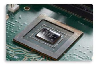
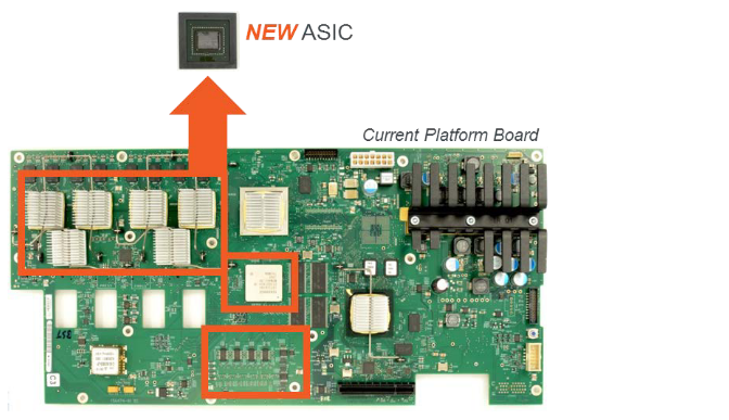
The TEK049 ASIC also incorporates display processing hardware that enables the 4, 5 and 6 Series MSOs to support a large HD display with a lively update rate. Having 1920 x 1080 pixels available allows the oscilloscope to take advantage of the higher ADC resolution and facilitate the viewing of important signal details critical for engineers. In other oscilloscopes the display system compresses the ADC codes into the number of vertical pixels available, which keeps a user from seeing important details that the ADC actually captured. The TEK049 also enables a very fast update rate with 16-bit color depth. This fast update rate with gray scaling allows users to pick out key features of the waveform, further enhancing the viewing capabilities for those who demand fine signal details. Incorporating many functions into one ASIC enables lower system noise, as signals are processed without having to transmit them through a PCB. Figure 5 shows a previous generation oscilloscope chipset with the same functions as the new TEK049.
Lower Noise and Greater Gain for High B/W, Low V/Div Settings
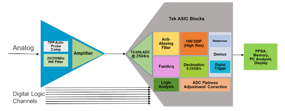
Also playing a critical role are new ASICs that enable the oscilloscope’s ability to support a wide range of full scales on the scope’s display. In the 4, 5 and 6 Series MSOs, an amplifier and attenuator system in the front end adjust the gain to always take advantage of the ADCs full scale. The amplifier noise needs to be very low to take advantage of the high-resolution ADC and enable the scope to be used at high bandwidths and at low volts-per-division settings. The new TEK061 ASIC (Figure 4b) in the 6 Series MSO provides industry leading performance at high bandwidth and small vertical scales. The new TEK026D (Figure 4c) ASIC is available on 4, 5 and 6 Series and ensures very low noise and even enables accurate probing to 1 GHz without the addition of noise from a probe amplifier. A general block diagram of the system is shown in Figure 6.
Hardware Filter Techniques for Improving Vertical Resolution
For years, Tektronix has provided noise reduction techniques and vertical resolution enhancements to achieve greater than 8-bit vertical resolution on instruments equipped with 8-bit ADCs. More detail on this is available in “Tools to Boost Oscilloscope Measurement Resolution to More than 11 Bits”. For this paper, we focus on techniques that can be used on single-shot acquisitions, as opposed to waveform averaging or equivalent-time sampling.
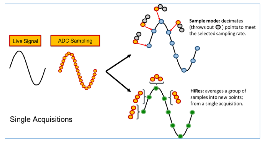
In general, oscilloscope ADCs are always running at maximum sample rate, no matter what the settings are. When lower sample rates are set by the user, sample points are decimated (thrown out) to store the desired record length / sample rate combination. This mode, in which extra samples are thrown out, is called “sample mode”. Tektronix has traditionally offered a more productive use for “extra” samples with an approach called high resolution or “HiRes” mode. Sample points are averaged together to create the desired sample rate in a process often referred to as ‘boxcar averaging’. Each sample point is made up of more information, providing better accuracy, and effectively delivering higher vertical resolution. Figure 7 illustrates sample mode vs HiRes (boxcar averaging) mode. This technique is widely-used today.
Using boxcar averaging, the increase in bits of vertical resolution is:
0.5 logD
where: D is the decimation ratio, or the maximum sample rate / actual sample rate. Predictably, the ability to improve vertical resolution is limited by the inherent noise in the system. For example, if the sample points are acquired by an ADC after going through an amplifier/attenuator with a high noise floor; the decreased accuracy of those points will counteract the resolution enhancements gained by boxcar averaging or traditional “HiRes” mode. It is important to recognize that high resolution mode works most effectively if the analog signal conditioning and the ADC sampling are working together to optimize live signal behavior.
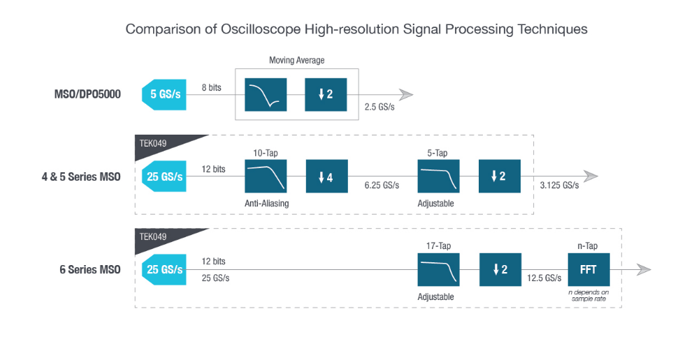
The 4, 5 and 6 Series MSOs improve even further on the boxcar averaging, or “HiRes” approach. In the traditional approach, high frequency noise is limited by the anti-aliasing filter which has a relatively high bandwidth.
The new high-resolution mode (dubbed High Res) uses hardware in the TEK049 ASIC to not only perform averaging, but also implement anti-aliasing filters and a uniquely-designed set of finite impulse response (FIR) filters for each sampling rate to ensure the user gets the best high-resolution representation of the original signal being measured.
The FIR filter maintains the maximum bandwidth possible for the selected sample rate, while preventing aliasing and removing noise energy from above the usable bandwidth. Figure 8 shows a depiction of the differences in filter use.
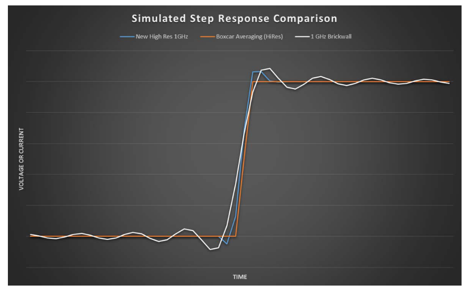
On the 4, 5 and 6 Series MSOs, the low-pass response for each filter is designed for a healthy balance between noise rejection and transient step response. While a brickwall filter might be considered for maximum noise rejection, it would provide non-optimal transient response. Gibbs phenomenon describes the effect in which a large discontinuity in frequency response (such as a brickwall filter) causes ringing and over/undershoot in the step response of a system, as shown in Figure 9. So, a balanced approach must be taken to limit noise without introducing poor step response. If not carefully balanced, an oscilloscope may provide low noise floor specs but lack accurate signal reproduction behavior in its waveform display.
High Res mode in the 4, 5 and 6 Series MSOs always provides at least 12 bits of vertical resolution and provides up to 16 bits of vertical resolution at 125 MS/s sample rates, or less.
ASIC Enables Triggering and Fast Display of High-Resolution Samples
In addition to viewing higher resolution signals; users must be capable of capturing events with confidence. Therefore, an oscilloscope’s trigger system must be equipped to handle the higher resolution to capture behavior that is being displayed in a consistent fashion. Because the TEK049 ASIC performs DSP filtering in real-time, using hardware blocks ahead of the trigger system, the trigger may be based on the processed high-resolution samples. This contrasts with traditional HiRes (boxcar averaging) methods which were applied to stored samples but not to the trigger signal, making it possible for high frequency transients or spikes to create false triggers not visible on the displayed screen.
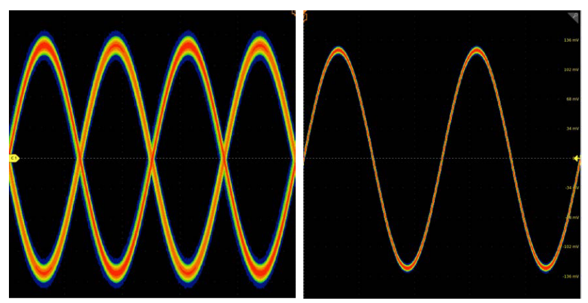
Tight integration of new improved High Res averaging and filtering with triggering also enables improved display modes such as FastAcq® waveform capture. This mode allows the instrument to capture over 500,000 waveforms per second and can be used in tandem with High Res to improve visual identification of signal detail critical to performance; such as power design validation. The left side of Figure 10 shows a noisy sine wave false-triggering on two edges in FastAcq mode, while the right side shows a FastAcq signal with High Res turned on. The right side is triggering on the filtered rising edge.
Resolution Without Accuracy is Meaningless
Higher resolution is meaningless if an instrument’s front end is noisy or prone to distortion, or if its sample rate is subject to time interval error. To quantify meaningful resolution; noise, distortion and jitter must be considered in addition to the number of bits in the ADC. To this end, the electronics industry has developed the notion of “Effective Number of Bits” (ENOB) to consider error due to noise, distortion, interleave errors and sampling jitter.
What is Effective Number of Bits (ENOB)?
ENOB represents the equivalent number of useful bits a digitizer or oscilloscope provides, taking into consideration instrument noise, harmonic distortion, linearity, and sampling jitter. It does so by inputting very high-quality signals and comparing the output of the digitizer to that input. Tektronix follows the methodology specified by the IEEE Standard for Digitizing Waveform Recorders (IEEE std. 1057). The ENOB is always lower than the number of bits in the ADC, due to the aforementioned noise and distortion. Typically, high-quality 8-bit ADC oscilloscopes have an ENOB between 4 and 6 bits, depending on the bandwidth and vertical scale selected. High resolution oscilloscopes with 10-bit or 12-bit ADCs typically have an ENOB between 7 and 9 bits. Since ENOB takes into account more than theoretical ADC resolution, it is a better measure of a digitizing system’s useful resolution.
Although it is an important factor in determining the accuracy of a digitizing system, ENOB is not an endall means for comparing measurement quality. It does not encompass errors in DC offset, gain, phase, and frequency. These errors must be considered separately; for example, if a measurement is being made that stresses accuracy in frequency performance, a better figure of merit may be Error Vector Magnitude (EVM). ENOB can hide poor frequency response or flatness on an oscilloscope.
To achieve higher ENOB, the 4, 5 and 6 Series MSO oscilloscopes incorporate enhancements highlighted earlier in this white paper:
- Higher performance ADC (12-bit)
- HD Display Processing Techniques
- Improved low noise, high gain analog front end
- Hardware filters to eliminate inherent noise
- Enabling high resolution triggering
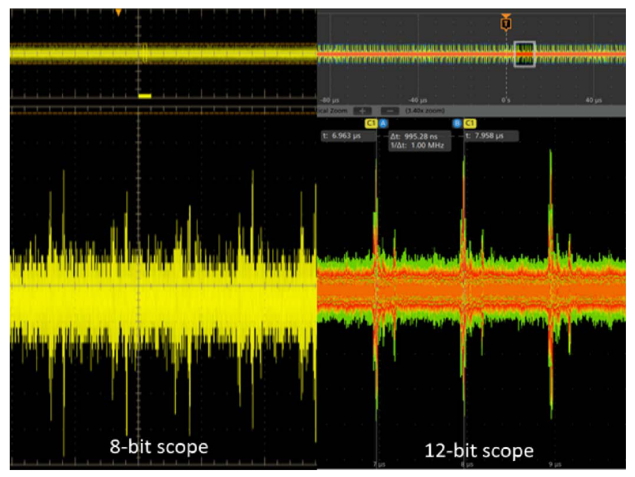
To see higher ENOB in action, the screenshot compares in Figure 11 are from a 1.5 V DDR3 power supply. The left side shows the DDR3 power supply captured by a traditional 8-bit oscilloscope with an ENOB of 6-bits. The supply appears to have significant noise and some prominent periodic voltage spikes. The right side of image shows the same supply but captured with a high-resolution oscilloscope with lower noise and better ENOB of over 7-bits. Notice how the baseline noise is heavily reduced as compared to the previous scope measurement. The prominent periodic spikes are also much more consistent in amplitude. Using an oscilloscope with higher ENOB can help in identifying the problem quicker and more easily. In this case the problem was 1 MHz switching noise from a 1.5 V buck regulator.
Summary
Higher vertical resolution in an oscilloscope can provide insight into important signal details. However, delivering this resolution means more than adding bits to the ADC. The 4, 5 and 6 Series MSOs incorporate a multi-faceted approach that combines not only higher ADC resolution, but also digital signal processing, trigger system integration, higher ENOB and low-noise analog front ends to achieve an effective increase in resolution.
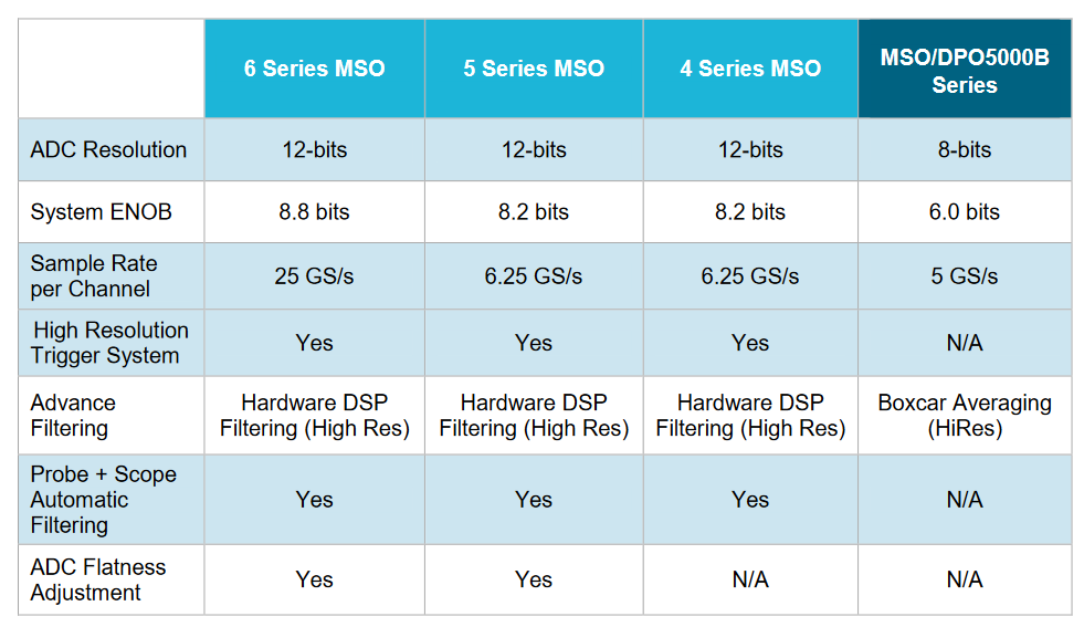
Comparing 4, 5 and 6 Series MSO Performance to a Previous Generation Instrument
Find more valuable resources at TEK.COM
Copyright © Tektronix. All rights reserved. Tektronix products are covered by U.S. and foreign patents, issued and pending. Information in this publication supersedes that in all previously published material. Specification and price change privileges reserved. TEKTRONIX and TEK are registered trademarks of Tektronix, Inc. All other trade names referenced are the service marks, trademarks or registered trademarks of their respective companies.
1/20 48W-61648-0