The power and flexibility of modern test equipment continues to evolve and expand. This application note discusses how a Tektronix 2 Series MSO Mixed Signal Oscilloscope and a low-cost USB-based realtime spectrum analyzer can be used to validate the operation of a mixed domain circuit.
Description of circuit under test
The circuit under test is a programmable RF synthesizer. This is a phase-locked loop (PLL) based RF synthesizer with output in the 2.4 GHz frequency range. The specific output frequency is programmed via a three-wire SPI bus. A microcontroller provides the SPI-bus signals to the synthesizer chip. The control voltage for the voltage-controlled oscillator (VCO) is available for examination along with the SPI bus and RF output. The validation test consists of sending a series of frequency-setting commands via the SPI bus. The response of the device under test (DUT) is examined and validated for proper operation.
Set up the decode on a specific frequency hop
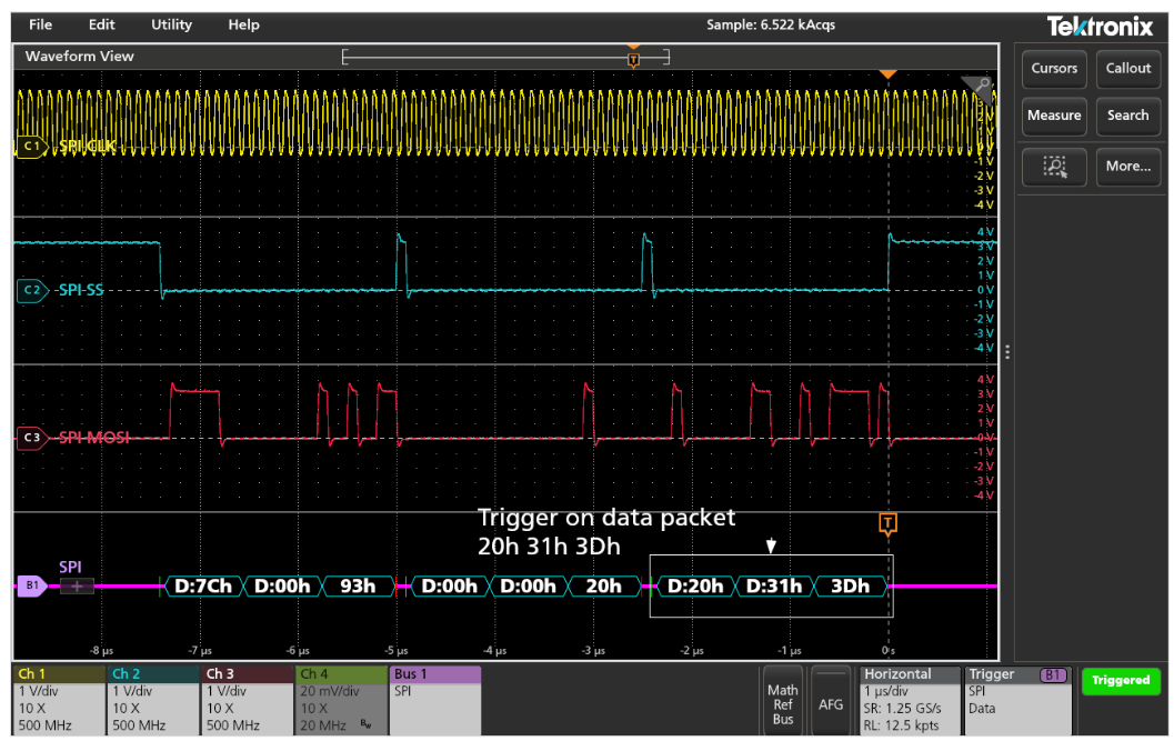
The first step is to set up the decode of the three-wire SPI bus and trigger on a specific frequency hop. This is uniquely identified by the last three data words of the instruction sent on the bus. In this case, the trigger is set up to find and acquire the three-byte sequence 20h 31h 3Dh (0x20313D).
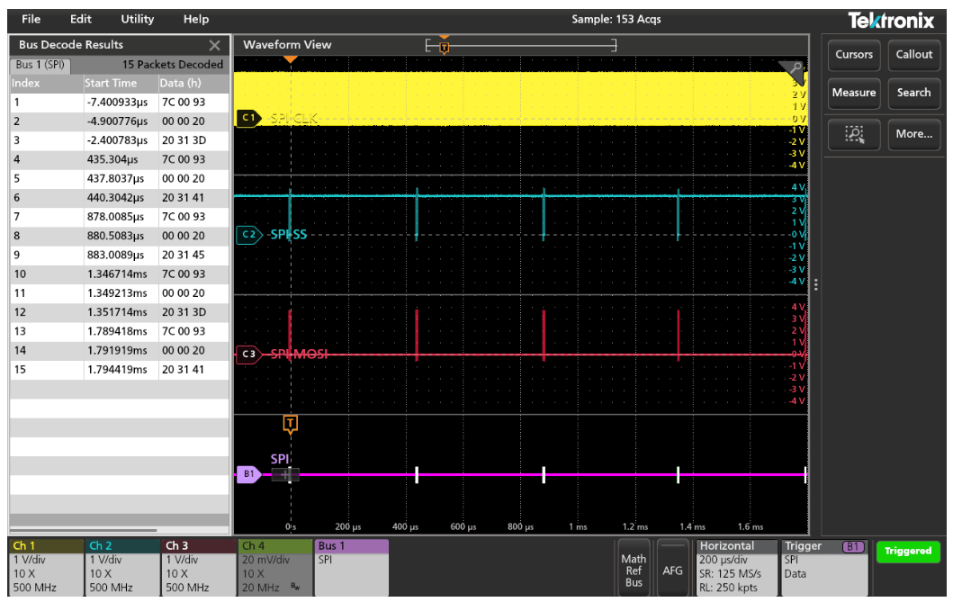
The validation sequence used here will change the frequency through three discrete steps. The horizontal scale is changed to acquire several consecutive steps, and a bus decode table is added to be able to see all of the bus values (since the waveform view will be too compressed to read inline). Of course, the Zoom function can be used to view the decode values directly on the bus waveform view as shown in the previous image.
2-MSO Option
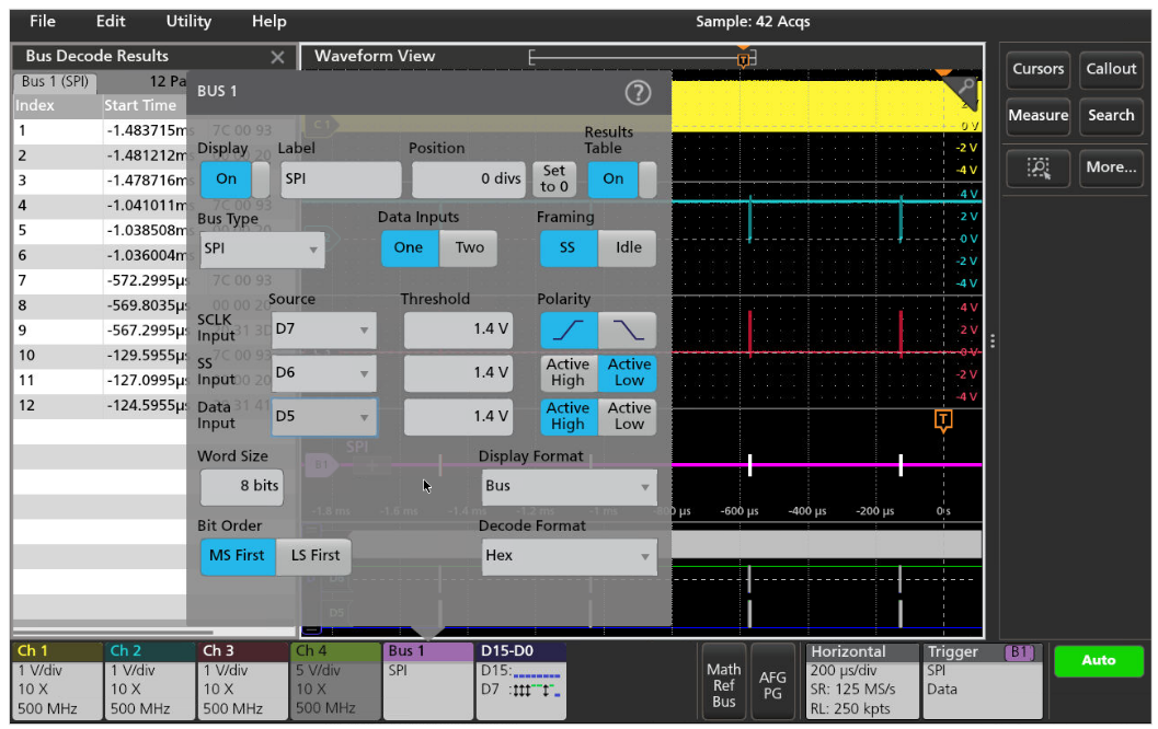
When the oscilloscope is equipped with the 2-MSO option, the logic probe can be used to acquire the SPI bus signals, freeing the analog channels to look at other signals in the system. Here the Bus 1 definition is changed to use digital channels D5, D6 and D7.
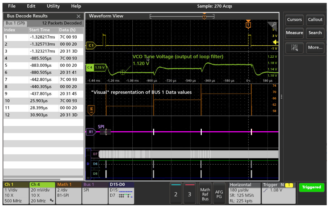
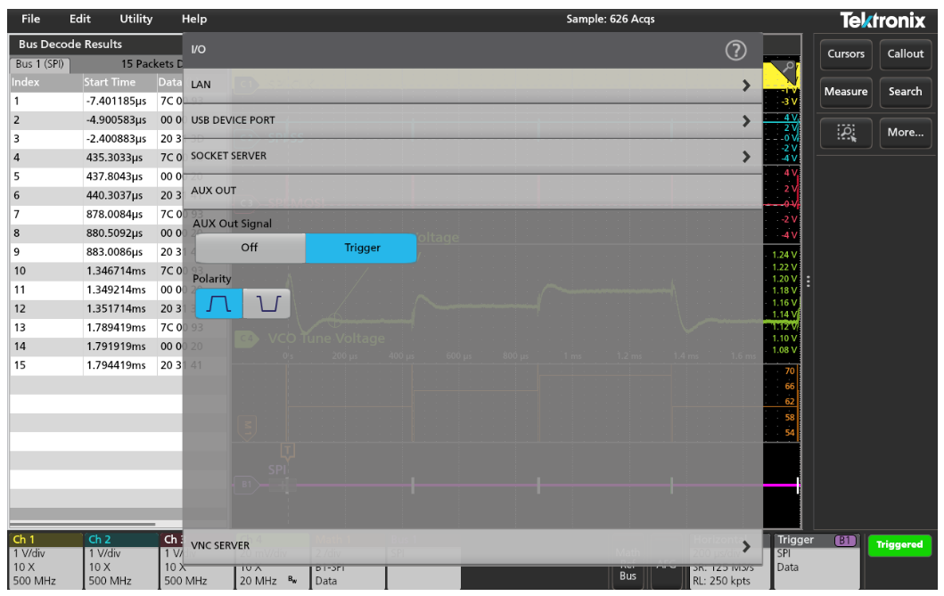
The analog channels are now free to examine other signals in the system. The system’s synchronization pulse is now probed with channel 1 and is used as the Trigger source. The control voltage for the VCO inside of the synthesizer is probed with channel 2. The change in this control voltage in response to the SPI commands is easily observed. However, it may be difficult to visualize the SPI data changes over time because they are just listed as numbers in the decode table. In the Math system of the MSO, a waveform can be added that graphically plots the data values sent on the bus. This makes it easy to see the correlation between the bus data and the resulting VCO tune voltage.
Synchronize RF data acquisition with the oscilloscope
The RF output of the synthesizer is in the 2.4 GHz frequency range. This exceeds the input bandwidth of the MSO, so this will be observed on the RSA306B USB-based Realtime Spectrum Analyzer. To synchronize the acquisition of the RF data with the oscilloscope, the AUX out is configured to provide a pulse when the oscilloscope is triggered. This pulse is then applied to the Ext Trigger input on the RSA.
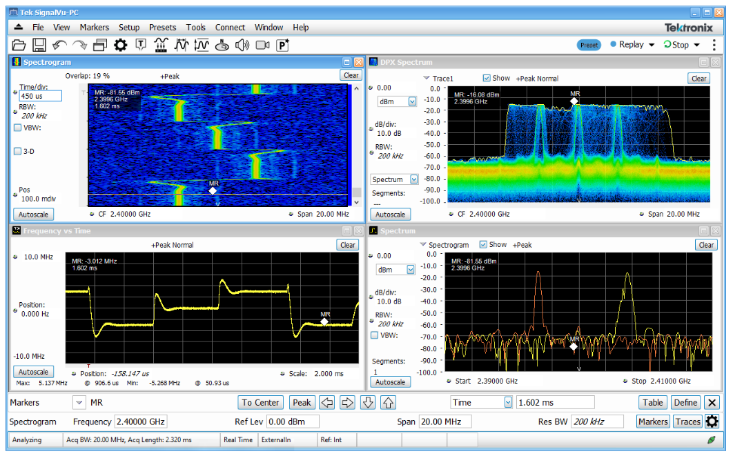
Armed with the oscilloscope trigger, the RSA acquires the RF signal synchronously with the oscilloscope’s analog and digital waveforms. The RF signal characteristics can then be examined to ensure that the behavior is meeting expectations.
In the example below, the realtime spectrum (DPX Spectrum) is shown, which illustrates the composite view of the instantaneous spectral content of the frequency hopping signal. The Spectrogram shows the seamless spectral history of the signal, and the Frequency vs Time display shows the “demodulated” frequency deviation of the signal. These waveforms match the expectation of the RF output based on the VCO tune voltage variation shown on the oscilloscope.
Conclusion
Capabilities of modern low-cost instrumentation like the Tektronix 2 Series MSO Mixed Signal Oscilloscope and the RSA306B USB-based Realtime Spectrum Analyzer can be used in conjunction to perform time-correlated multi-domain analysis. Synchronizing the acquisition of the RF data on the RSA with the triggered acquisition on the MSO is a simple matter of coupling the trigger output of the oscilloscope to the trigger input of the RSA. This combination enables full time-correlated validation of the analog, digital/bus signals at the DUT as well as the microwave RF output characteristics. This multi-domain choreography enables full mixed domain validation of the operation of a device like this programmable synthesizer chip.
Find more valuable resources at TEK.COM
Copyright © Tektronix. All rights reserved. Tektronix products are covered by U.S. and foreign patents, issued and pending. Information in this publication supersedes that in all previously published material. Specification and price change privileges reserved. TEKTRONIX and TEK are registered trademarks of Tektronix, Inc. All other trade names referenced are the service marks, trademarks or registered trademarks of their respective companies.
011823 48W-73980-0