THIS APPLICATION NOTE
- Gives a brief orientation on the physical layer and packet structures of CAN / CAN FD, LIN, and FlexRay buses, with a goal of providing just enough detail to help with troubleshooting
- Explains how to set up decoding on an oscilloscope equipped with CAN / CAN FD, LIN or FlexRay decoding
- Explains how to interpret decoded serial bus data on an appropriatelyequipped oscilloscope
- Explains what triggering and searching options are available
With optional serial triggering and analysis capability, Tektronix oscilloscopes become powerful tools for embedded system designers working with CAN, LIN, and FlexRay buses. In this application note the 5 Series MSO is used to demonstrate decoding and triggering on these buses.
Tektronix 2, 4, 5 and 6 Series MSO oscilloscopes support CAN, LIN, and FlexRay triggering and analysis. The operation of all of these instruments is practically identical to the 5 Series MSO used in this application note. See the Oscilloscope Selection Guide for more information.
Introduction
Embedded systems applications are growing rapidly in the automotive industry. Many vehicle designs use CAN, LIN or FlexRay to communicate among electronic control units (ECUs), and between ECUs and sensors, actuators and displays. These buses are critical in providing real-time communications in and among important subsystems from braking systems to infotainment systems.
CAN, LIN, and FlexRay are relatively mature bus protocols and are designed to be robust and easy to integrate. Even so, communications can be impacted by noise, board layout, and power-up/down timing. Problems can include excessive bus errors and lock-ups. Unlike basic protocol analyzers, oscilloscopes equipped with protocol decoding, can be used to see both the decoded bus traffic, as well as signal quality.
Perhaps more importantly, oscilloscopes can be used to troubleshoot problems at the system level. Automobiles rely on extensive networks of sensors, actuators and displays, and many problems involve bus timing relative to I/O events or values. Oscilloscopes are well-suited for looking at I/O signals and bus transactions at the same instant.
This ability to see bus signals and decoded traffic at the electrical level and systems level make oscilloscopes the best choice for troubleshooting.
CAN/CAN FD
Controller Area Network (CAN) was originally developed in the 1980s by the Robert Bosch GmbH as a low cost communications bus between devices in electrically noisy environments. Mercedes-Benz became the first automobile manufacturer in 1992 to employ CAN in their vehicle systems. Today, every automotive manufacturer uses CAN controllers and networks to control a variety of Electronic Control Units (ECUs) in their automobiles. It is the primary bus used for engine timing controls, anti-lock braking systems and powertrain controls to name a few. And due to its electrical noise tolerance, minimal wiring, excellent error detection capabilities and high data transfer speeds, CAN expanded into other applications such as industrial control, marine, medical, aerospace, and more.
As vehicle networks have evolved to support more functions, a need has arisen to support faster data communication between nodes. This has led to the following CAN standards:
- CAN FD is a higher speed version of CAN that can achieve a maximum data rate of 8 Mbps with a payload up to 64 bytes long compared to the maximum data rate of 1 Mbps and payload of 8 bytes for CAN. The first version of the CAN FD standard was released in 2012 but later updated into an ISO standard (ISO CAN FD) in 2015. The ISO version introduced additional safeguards to improve communication reliability. The original version is now known as non-ISO CAN FD and is not compatible with ISO CAN FD.
- CAN XL is a new standard developed by CAN in Automation(CiA). This third generation of CAN meets requirements of E/E zone architectures for future vehicles. Its main usage will be as a backbone network to bridge the gap of bitrates and data between classical CAN/CAN FD and Ethernet 100BASE-T1. CAN XL supports data rate up to 20 Mb/s and data field length up to 1 to 2048 bytes.
HOW IT WORKS
CAN / CAN FD / CAN XL defined the data link layer of the ISO 7-layer model. While there are various physical layers specifications (include fault tolerant and single wire), ISO 11898 is the most prolific — used in most applications. It is a (differential) 2-wire interface running over a shielded twisted pair (STP), unshielded twisted pair (UTP) or ribbon cable. The data rate is defined by the user, with 1 Mb/s being the fastest for CAN, 8 Mb/s the fastest for CAN FD and 20 Mb/s the fastest for CAN XL. The lowest rate is 20 kb/s. All the nodes on the bus must communicate at the same bus speed. (There are configurations in which all the nodes change their bus speed to a higher rate for reflashing or diagnostics but then return back to their normal rate.) Maximum cable length depends on the data rate used. The maximum line length can be thousands of meters at low speeds; 40 meters at 1 Mb/s is typical. Termination resistors are used at each end of the cable.
Non Return to Zero (NRZ) bit encoding is used with bit stuffing to ensure compact messages with a minimum number of transitions and high noise immunity. The CAN bus interface uses an asynchronous transmission scheme where any node may begin transmitting anytime the bus is free. Messages are broadcast to all nodes on the network. In cases where multiple nodes initiate messages at the same time, CAN / CAN FD uses bitwise arbitration and CAN XL uses CSMA/CR (carrier sense multiple access/ collision resolution) to determine which message is higher priority. Messages can be one of four types:
| MESSAGE TYPES | DESCRIPTION | |
| Data Frame | Used to transmit data | (CAN XL supports only Data Frames.) Data and Remote frames are controlled by start and stop bits at the beginning and end of each frame and include the following fields: Arbitration field, Control field, Data field, CRC field and an ACK field. |
| Remote Transmission Request (RTR) Frame | Used to request data (rarely used) | |
| Error Frame | Any node on the bus that detects an error transmits an error frame which causes all nodes on the bus to view the current message as incomplete and the transmitting node to resend the message | |
| Overload Frame | Initiated by receiving devices to indicate they are not ready to receive data yet | |
Structure of Data and Remote Transmission Request Frames
| CAN 2.0 | SOF 1 bit |
Arbitration Field 11 bits (Std ID) 29 bits (Ext ID) | Control Field 6 bits |
Data Field 0-8 bytes |
CRC Field 16 bits |
ACK 2 bits |
EOF 7 bits |
INT 3 bits |
| CAN FD | SOF 1 bit |
Arbitration Field 12 bits (Std ID) 32 bits (Ext ID) | Control Field 8 or 9 bits |
Data Field 0-64 bytes |
CRC Field or 22 bits |
ACK 2 bits |
EOF 7 bits |
INT 3 bits |
| CAN XL | SOF 1 bit |
Arbitration Field 11 bits (Priority ID), 1 bit (RRS), 1 bit (IDE), 1 bit (FDF) 1 bit (XLF) | Control Field 81 bits |
Data Field 0-2048 bytes |
CRC Field 32 bits (FCRC) and 4 bits (FCP) | ACK Field 4 bits (DAS) 2 bits (ACK) |
EOF 7 bits |
INT 11 bits |
| FIELD | DESCRIPTION |
| SOF | The frame begins with a start of frame (SOF) bit which is the same for CAN, CAN FD, and CAN XL. |
| Arbitration | Includes an Identifier (address) and the Remote Transmission Request (RTR) bit used to distinguish between a data frame and a data request frame, also called a remote frame. The identifier can either be standard format (11 bits - version 2.0A) or extended format (29 bits - version 2.0B). CAN FD shares the same addressing as CAN for standard and extended formats but removes the RTR bit and maintains a dominant r1 bit. Control Consists of six bits including the Identifier Extension (IDE) bit which distinguishes between a CAN 2.0A (11 bit identifier) standard frame and a CAN 2.0B (29-bit identifier) extended frame. For CANXL, we have 11 bit Priority Identifier, followed by 1 bit Remote Request Substitute(RRS), 1 bit Identifier Extension (IDE), 1 bit FD Form Identifier(FDF), and 1 bit XL Format Identifier(XLF). |
| Control | Includes the Data Length Code (DLC), a four-bit indication of the number of bytes in the data field of a Data frame or the number of bytes being requested by a Remote frame. CAN FD uses eight or nine bits in the Control Field and uses the IDE, r0 and DLC bits. Three additional bits are added that include Extended Data Length (EDL) used to determine if packet is CAN or CAN FD, Bit Rate Switch (BRS) used to separate arbitration phase from data phase and Error State Indicator (ESI). The same four-bit DLC is used differently in CAN FD for lengths ≥ 8. CANXL has 81 bit control field, it consists of 1 bit Reserve bit for XL Format(resXL), 4 bit Aribtration to Data Sequence(ADS), 8 bit Service Data Unit Type(SDT), 1 bit Simple Extended Content(SEC), 11 bit Data Length Code (DLC), 3 bit Stuff Bit Count(SBC), 13 bit Preface CRC(PCRC), 8 bit Virtual CAN Network ID(VCID) and 32 bit Acceptance Field(AF). Control Consists of six bits including the Identifier Extension (IDE) bit which distinguishes between a CAN 2.0A (11 bit identifier) standard frame and a CAN 2.0B (29-bit identifier) extended frame. For CANXL, we have 11 bit Priority Identifier, followed by 1 bit Remote Request Substitute(RRS), 1 bit Identifier Extension (IDE), 1 bit FD Form Identifier(FDF), and 1 bit XL Format Identifier (XLF). |
| Data | The CAN data field consists of 0 to 8 bytes of data. CAN FD supports 0 to 8 bytes but has an increased payload ability to support 12, 16, 20, 32, 48 or 64 bytes. CAN XL supports 1 to 2048 bytes of data. |
| CRC | A 15-bit cyclic redundancy check code and a recessive delimiter bit is used in CAN. CAN FD uses 17 bits (plus CRC delimiter bit) for payloads ≤ 16 bytes or 21 bits (plus CRC delimiter bit) for ≥ 16 bytes. There are 4 additional stuff bits used for CAN FD. CAN XL uses 32 bits and 4 additional Frame Check Pattern (FCP) bits. |
| ACK | The Acknowledge field is two bits long. The first is the slot bit, transmitted as recessive, but then overwritten by dominant bits transmitted from any node that successfully receives the transmitted message. The second bit is a recessive delimiter bit. There is a slight difference in CAN FD where the receiver recognizes 2 bit times as a valid ACK. For CAN XL, there is an additional 4 bit Data to Arbitration Sequence(DAS) at the start of ACK field. |
| EOF | Seven recessive bits indicate the end of frame (EOF). |
The intermission (INT) field of three recessive bits indicates the bus is free. Bus Idle time may be any arbitrary length including zero.
SETTING UP CAN / CAN FD / CAN XL BUS DECODING
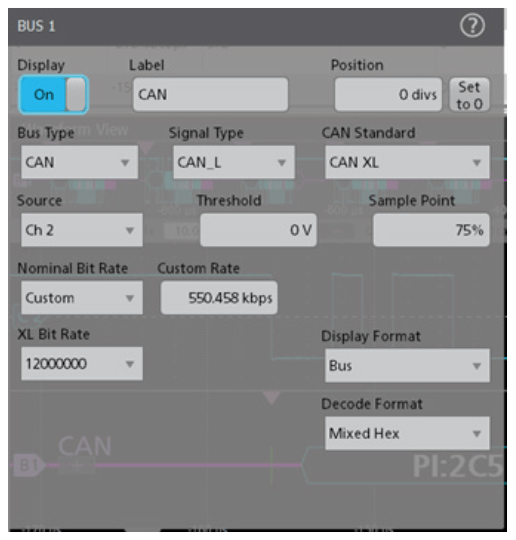
On Tektronix oscilloscopes equipped with CAN decoding and triggering, pressing the front panel Bus button lets you define inputs to the scope as a bus. To enable the oscilloscope to decode information being transferred, you enter some basic parameters:
- CAN standard
- Type of signal
- Input channel
- Bit rate(s)
- Voltage threshold
- Sample point (as a percent of bit time)
The CAN bus is a differential signal. Although the oscilloscope can acquire and decode the bus using single-ended probing, the signal fidelity and noise immunity is improved by using differential probing.
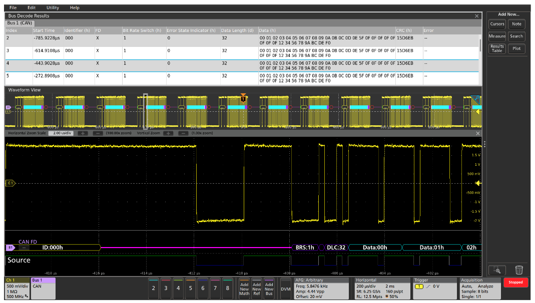
INTERPRETING CAN / CAN FD / CAN XL BUS INFORMATION
The decoded bus waveform indicates the elements of a CAN message using color-coded graphics.
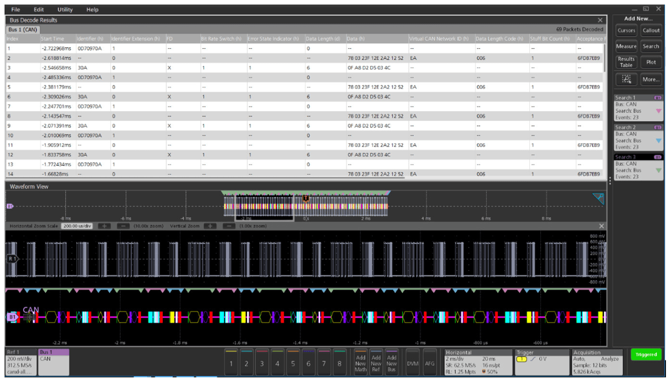
For firmware engineers, the Results Table format may be more useful. This time-stamped display of bus activity can be easily compared to the software listings, and provides easy calculation of the execution speed.
The Results Table also provides linkage back to the waveform displays. You can tap a line in the tabular display and the oscilloscope automatically zooms in on the corresponding bus signals and resulting decoded bus waveform, shown in the lower section of the screen.
| CAN BUS ELEMENT | INDICATED BY |
| Start of Frame is indicated by a vertical green bar. |
 |
| Bit Rate Switch (BRS) and Data Length Control (DLC) are shown in purple boxes. DLC values can be displayed in either hex or binary. |
 |
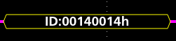
| Identifiers are shown in yellow boxes. Identifier values can be displayed in either hex or binary. |
 |
| Data is shown in cyan boxes. Data values can be displayed in either hex or binary. |
 |
| CRC values are shown in purple boxes. |
 |
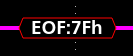
| End Of Frame is indicated by a red box. |
 |
SYMBOLIC CAN BUS DECODING
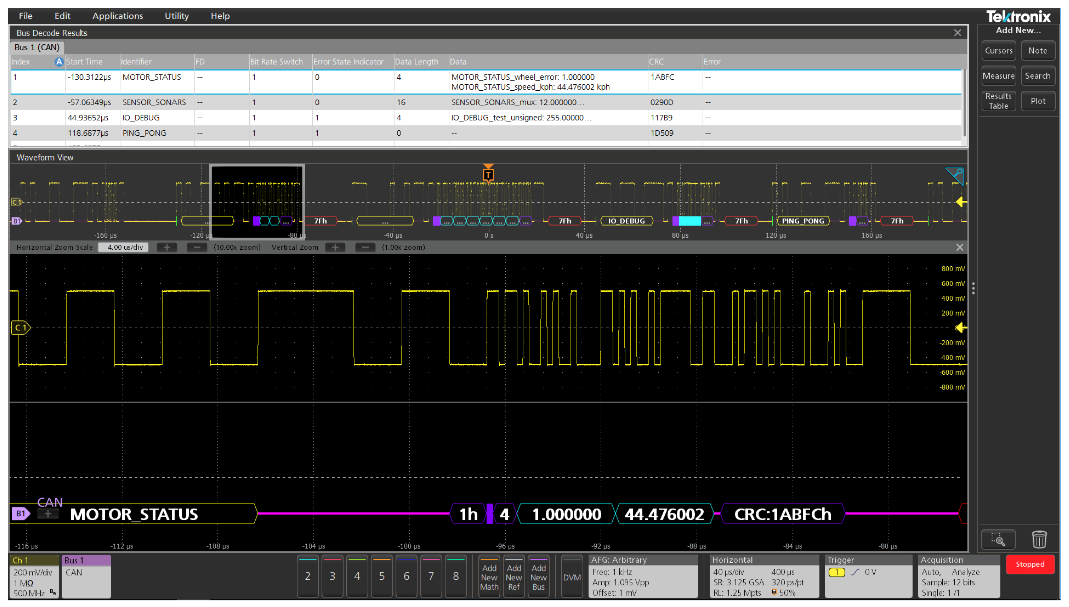
Symbolic can bus decoding, as defined in DBC database files, can be used to display CAN, CAN FD and CAN XL bus traffic in an easy-to-read format. By loading a DBC database file into the scope, you can view CAN traffic as text, rather than raw hex values. The file syntax is standardized, but the specific encoding and translation is proprietary and closely held by manufacturers.
In this example, a few symbolic message and signal values are shown in the bus waveform and results table displays.
TRIGGERING ON CAN BUS ACTIVITY
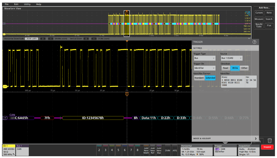
Begin able to trigger an acquisition based on specific bus activity makes the oscilloscope an important tool in system-level debugging. When the bus trigger is correctly set up, the oscilloscope will capture all input signals synchronized to the specified bus activity. This example shows the oscilloscope triggering on a write to extended identifier 12345678 hex.
CAN XL supports trigger options Start of Frame and End of Frame. The full CAN / CAN FD bus triggering capabilities are mentioned in the table.
| TRIGGER ON | DESCRIPTION | |
| Start of Frame | Trigger on any SOF field | |
| Frame Type | Data Frame, Remote Frame, Error Frame, or Overload Frame | |
| FD Bits | FD Bit Rate Switch Bit, FD Error State Indicator Bit | |
| Identifier | Any specific 11- or 29-bit identifier values with Read / Write qualification | |
| Data | Any user-specified CAN data | |
| Missing Ack | Trigger anytime the receiving device does not provide an acknowledge | |
| Bit Stuffing Error | Trigger if a bit stuffing error is detected | |
| FD Form Error | Trigger on invalid bits in the FD message frame | |
| Any Error | Trigger on Missing Ack, Bit Stuffing, and FD Form errors | |
| End of Frame | Trigger on any EOF field | |
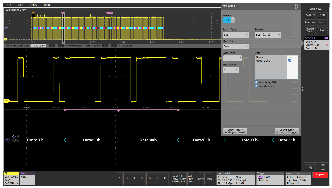
SEARCHING FOR CAN BUS ACTIVITY
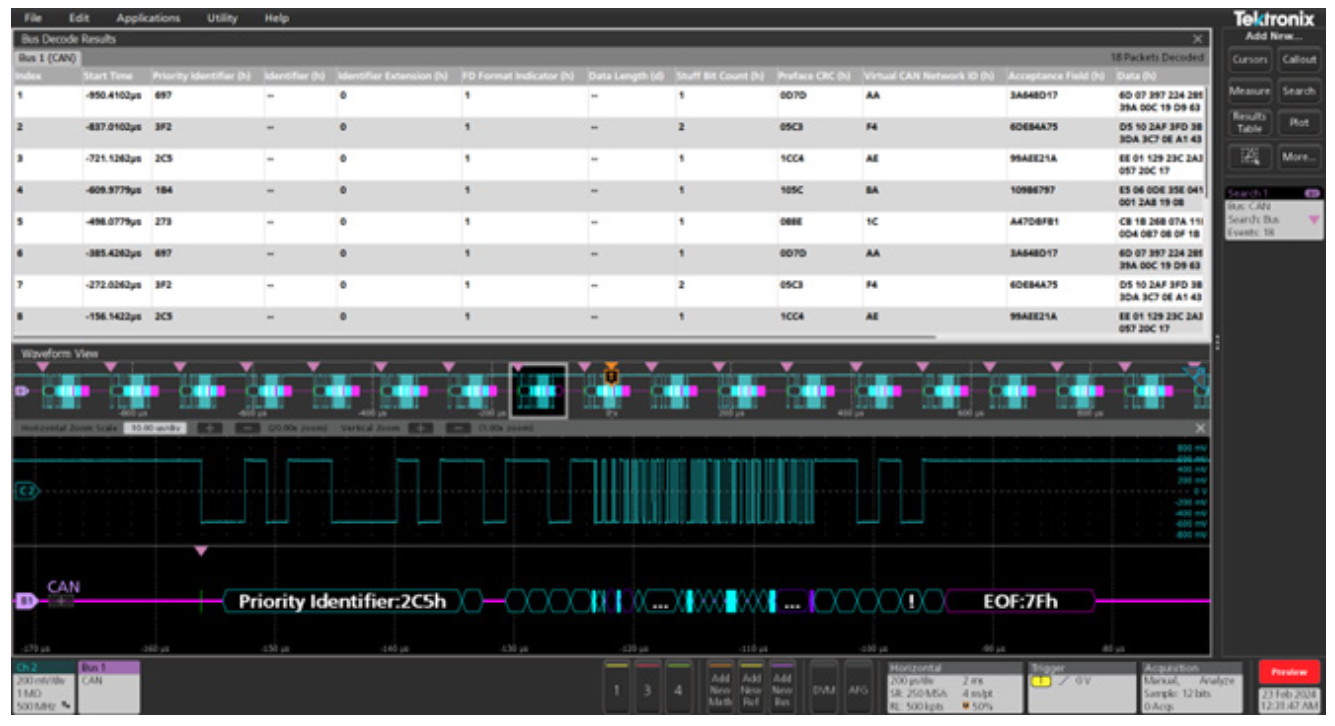
On a Tektronix oscilloscope equipped with CAN / CAN FD / CAN XL decoding, you can use the automated Wave Inspector search to find all of the bus events that meet specific search criteria and determine how many of them occurred during an acquisition. The setup is similar to bus trigger setup, with the same alternatives for specifying criteria. In Figure 6, the search function is set to automatically search for data values of 00 hex. It found and marked 10 occurrences.
The CAN XL supports the following Search options:
| Start of Frame | Search on any SOF field |
| Frame Type | XL Data Frame |
| Priority Identifier | Any specific 11- bit values for Identifier |
| Data | Any user-specified CAN data |
| XL Bits | Option to select specific bits for CAN XL |
| End of Frame | Search on any EOF field |
| Error | User can search for Missing Ack, XL Form Error, CRC, Any Error |
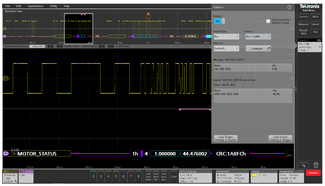
SYMBOLIC SEARCHING
In addition to searching on hex and binary values, when symbolic decoding is used Wave Inspector can automatically search on symbolic messages and signal values. In this example, search found the MOTOR_STATUS message with the MOTOR_STATUS_speed_kph signal value of 44.476 kph.
MIXED CAN BUS SUPPORT
The existing CAN also supports Mixed mode decode capabilities. This helps in automotive setup where the CAN network has different CAN modes like CAN 2.0, CAN FD and CAN XL. The user can select CAN 2.0 + CAN FD + CAN XL from standard type.
| CONFIGURATION OPTIONS FOR MIXED MODE CAN | |
| SD Bit Rate | Arbitration bit rate for CAN FD and CAN XL. This is also a bit rate for CAN 2.0. |
| FD Bit Rate | Data rate for CAN FD data transfer. |
| XL Bit Rate | Data rate for CAN XL data transfer |

| SEARCH OPTIONS FOR MIXED MODE CAN | |
| Start of Frame | Search on any SOF field |
| Type of Frame | XL Data Frame |
| Priority Identifier | Any specific 11-bit values for Identifier |
| Data | Any user-specified CAN data |
| XL Bits | Option to select specific bits for CAN XL |
| End of Frame | Search on any EOF field |
| Error | User can search for Missing Ack, XL Form Error, CRC, Any Error |
| FD Bits | Option to select specific bits for CAN FD |
| Identifier | Any specific 11- or 29-bit identifier values with Read / Write qualification |
LIN
The Local Interconnect Network (LIN) bus was developed by the LIN consortium in 1999 as a lower cost alternative to the CAN bus for applications where the cost, versatility, and speed of CAN were excessive. These applications typically include communications between intelligent sensors and actuators such as window controls, door locks, rain sensors, windshield wiper controls, and climate control, to name a few.
However, due to its electrical noise tolerance, error detection capabilities, and high speed data transfer, CAN is still used today for engine timing controls, anti-lock braking systems, powertrain controls and more.
HOW IT WORKS
The LIN bus is a low-cost, single-wire implementation based on the Enhanced ISO9141 standard. LIN networks have a single master and one or more slaves. All messages are initiated by the master with only one slave responding to each message, so collision detection and arbitration capabilities are not needed as they are in CAN. Communication is based on UART/SCI with data being sent in eightbit bytes along with a start bit, stop bit and no parity. Data rates range from 1 kb/s to 20 kb/s. While this may sound slow, it is suitable for the intended applications and minimizes EMI.
The LIN bus is always in one of two states: active or sleep. When it’s active, all nodes on the bus are awake and listening for relevant bus commands. Nodes on the bus can be put to sleep by either the Master issuing a Sleep Frame or the bus going inactive for longer than a predetermined amount of time. The bus is then awakened by any node requesting a wakeup or by the master node issuing a break field.

As shown in Figure 10, LIN frames consist of two main parts, the header and the response. The header is sent by the master while the response is sent by the slave. The header and response each have subcomponents:
| HEADER COMPONENTS | DESCRIPTION |
| Break Field | Used to signal the beginning of a new frame. It activates and instructs all slave devices to listen to the remainder of the header |
| Sync Field | Used by the slave devices to determine the baud rate being used by the master node and synchronize themselves accordingly |
| Identifier Field | Specifies which slave device is to take action |
| HERESPONSE COMPONENTS | DESCRIPTION |
| Data | The specified slave device responds with one to eight bytes of data |
| Checksum | Computed field used to detect errors in data transmission. The LIN standard has evolved through several versions that have used two different forms of checksums. Classic checksums are calculated only over the data bytes and are used in version 1.x LIN systems. Enhanced check- sums are calculated over the data bytes and the identifier field and are used in version 2.x LIN systems. |
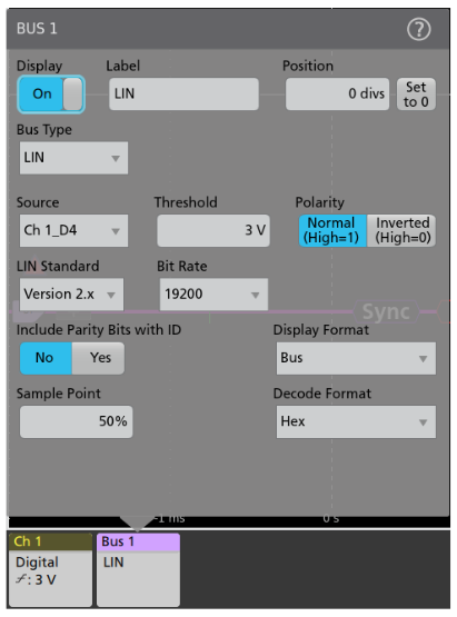
SETTING UP LIN BUS DECODING
On Tektronix oscilloscopes equipped with LIN decoding and triggering, pressing the front panel Bus button lets you to define inputs to the scope as a bus. To enable the oscilloscope to decode the information being transferred on the bus, you enter some basic parameters:
- Input channel
- LIN version being used
- Bit rate
- Polarity
- Threshold
- Where to sample the data (as a percent of bit time),
LIN signals can be captured using passive or active analog probes, but digital logic probes can also be used for acquiring LIN signals.
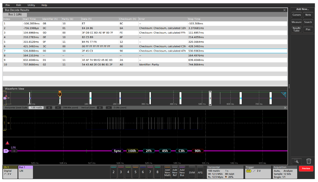
INTERPRETING THE LIN BUS
The decoded bus waveform graphically indicates the different elements of a LIN message.
| LIN BUS ELEMENT | INDICATED BY |
| Start of Frame is indicated by a vertical green bar. |
|
| Sync is shown in a purple box. |
 |
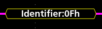
| Identifiers are shown in yellow boxes. Identifier values can be displayed in either hex, binary, or decimal. |
 |
| Data is shown in cyan boxes. Data values can be displayed in either hex or binary. |
 |
| Checksum values are shown in purple boxes (or red boxes, in case of errors). |
 |
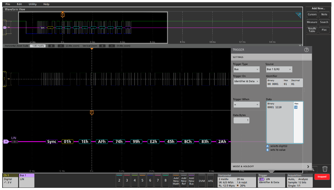
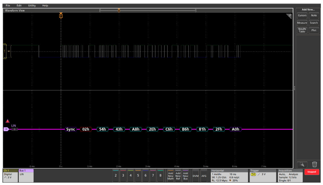
TRIGGERING ON LIN BUS ACTIVITY
With the LIN bus properly set up, the oscilloscope will be able to capture all of the input signals, based on the occurrence of a bus trigger event. In Figure 14, the oscilloscope has triggered when the identifier 01 hex is followed by a data value of 1E hex.
The full LIN bus triggering capabilities include the following trigger types:
| TRIGGER ON | DESCRIPTION |
| Sync | Any sync field |
| Identifier | Trigger on a specific identifier |
| Data | Trigger on specific data values or data ranges |
| Identifier & Data | Trigger on a combination of both identifier and data |
| Wakeup Frame | Any wakeup frame |
| Sleep Frame | Any sleep frame |
| Error | Sync errors, ID parity errors, or checksum errors |
These trigger types allow you to isolate different types of events a LIN bus and use them as triggers to view system activity. And with the other advanced serial features found in Tektronix oscilloscopes such as results tables and Wave Inspector search, you can easily debug LIN based automotive designs.
FlexRay
As cars get smarter and electronics find their way into more and more automotive applications, manufacturers are finding that existing automotive serial standards such as CAN and LIN do not have the speed, reliability, or redundancy required to address X-by-wire applications such as brake-by-wire or steer- by-wire. Today, these functions are dominated by mechanical and hydraulic systems. In the future they will be replaced by a network of sensors and highly reliable electronics that will not only lower the cost of the automobile, but also significantly increase passenger safety due to intelligent electronic based features such as anticipatory braking, collision avoidance, adaptive cruise control, etc.
HOW IT WORKS
FlexRay is a differential bus running over either a Shielded Twisted Pair (STP) or an Un-shielded Twisted Pair (UTP) at speeds up to 10 Mb/s, significantly faster than LIN’s 20 kb/s or CAN’s 1 Mb/s rates. FlexRay uses a dual channel architecture which has two major benefits. First, the two channels can be configured to provide redundant communication in safety critical applications such as X-by-wire to ensure the message gets through. Second, the two channels can be configured to send unique information on each at 10 Mb/s, giving an overall bus transfer rate of 20 Mb/s in less safety-critical applications.
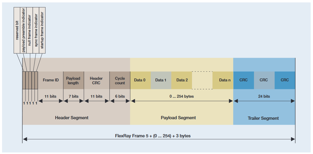
FlexRay uses a time triggered protocol that incorporates the advantages of prior synchronous and asynchronous protocols via communication cycles that include both static and dynamic frames. Static frames are time slots of predetermined length allocated for each device on the bus to communicate during each cycle. Each device on the bus is also given a chance to communicate during each cycle via a Dynamic frame which can vary in length (and time). The FlexRay frame is made up of three major segments; the header segment, the payload segment, and the trailer segment. Each segment is made up of one or more components:
| HEADER SEGMENT COMPONENTS | DESCRIPTION |
| Indicator Bits | The first five bits indicate the type of frame being transmitted. Choices include Normal, Payload, Null, Sync, and Startup. |
| Frame ID | Defines the slot in which the frame should be transmitted. Frame IDs range from 1 to 2047 with any individual frame ID being used no more than once on each channel in a communication cycle. |
| Payload Length | Indicates how many words of data are in the payload segment |
| CRC | Cyclic redundancy check (CRC) code calculated over the sync frame indicator, the startup frame indicator, the frame ID and the payload length |
| Cycle Count | The value of the current communication cycle, ranging from 0–63. |
| PAYLOAD SEGMENT COMPONENTS | DESCRIPTION |
| Data | The data field contains up to 254 bytes of data. For frames transmitted in the static segment the first 0 to 12 bytes of the payload segment may optionally be used as a network management vector. The payload preamble indicator in the frame header indicates whether the payload segment contains the network management vector. For frames transmitted in the dynamic segment the first two bytes of the payload segment may optionally be used as a message ID field, allowing receiving nodes to filter or steer data based on the contents of this field. The payload preamble indicator in the frame header indicates whether the payload segment contains the message ID. |
| TRAILER SEGMENT COMPONENTS | DESCRIPTION |
| CRC | Cyclic redundancy check (CRC) code calculated over all of the components of the header segment and the payload segment of the frame. |
Dynamic frames have one additional component that follows the Trailer CRC called the Dynamic Trailing Sequence (DTS) that prevents premature channel idle detection by the bus receivers.
SETTING UP FLEXRAY BUS DECODING
To set up decoding, you must specify some basic parameters describing the bus:
- Specify the FlexRay channel A or B
- Type of signal we’re probing (differential, half the differential pair, or the logic signal between the controller and the bus driver)
- Voltage thresholds. FlexRay requires two thresholds to be set when looking at non-Tx/Rx signals as it is a three-level bus. This enables the oscilloscope to recognize Data High and Data Low as well as the idle state where both signals are at the same voltage.
- Bit rate

DECODING AND TRIGGERING ON FLEXRAY
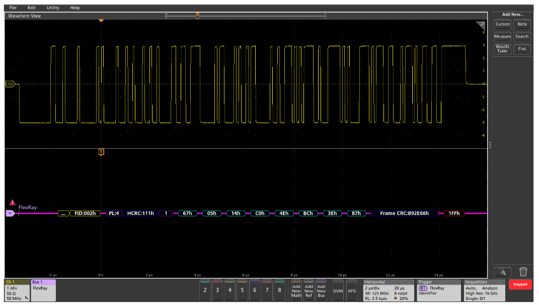
Once the bus is set up the oscilloscope will be able to isolate, capture, and display specific FlexRay bus events, as well as any other coincident signals. Such a time-correlated display allows you to verify causes and effects in the design. In this example the oscilloscope was set to trigger on the Frame ID value 002 hex.
The oscilloscope's FlexRay triggering capability includes the following types:
| TRIGGER ON | DESCRIPTION |
| Start of Frame | Triggers on the trailing edge of the Frame Start Sequence (FSS) |
| Indicator Bits | Normal, Payload, Null, Sync, or Startup frames |
| Identifier | Specific Frame IDs or a range of Frame IDs |
| Cycle Count | Specific Cycle Count values or a range of Cycle Count values |
| Header Fields | Combination of user specified values in any or all of the header fields including the Indicator Bits, Frame ID, Payload Length, Header CRC, and Cycle Count |
| Data | Trigger on up to 16 bytes of data. Data window can be offset by a user specified number of bytes in a frame with a very long data payload. Desired data can be specified as a specific value or a range of values |
| Identifier & Data | Trigger on a combination of Frame ID and data |
| End of Frame | Trigger on static frames, dynamic frames, or all frames |
| Error | Trigger on different error types including Header CRC errors, Trailer CRC errors, Null frame errors, Sync frame errors, and Startup frame errors |
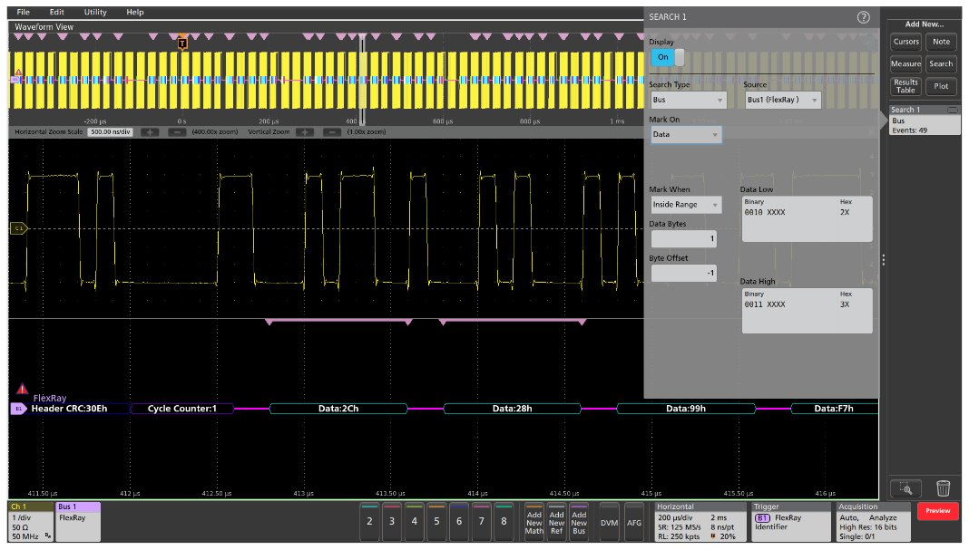
But how many of the events occurred? To find all of the bus events that meet a specific search criteria, you can use automated Wave Inspector search. The setup is similar to the bus trigger setup, allowing the oscilloscope to find and mark all of the specified bus events.
In the example above the oscilloscope was set up to trigger on a specific Frame ID. It captured and decoded approximately 80 FlexRay frames. Then Wave Inspector search was set up to go through the acquisition and and marked 49 occurrences within a range of data values. Each of the data values in the specified range is shown with the pink bracket icon. Using the arrow keys, you can instantly navigate between marked values.
And all of this was done with only 250,000 point record lengths. The 5 Series MSO, for example, can capture 62.5 Mpoints with standard record length, or 125 M points when equipped with extended record length.
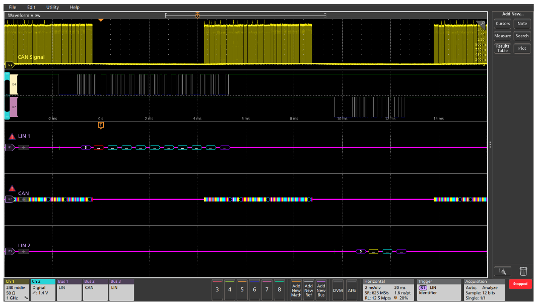
DECODING MULTIPLE BUSES AT ONCE
A powerful feature of the oscilloscope is the ability to define and decode many serial buses simultaneously. Going back to our earlier example with CAN bus; now imagine that the window controls are operated by a LIN bus. When the driver presses the Passenger Window Down control, a message is initiated on a LIN bus in the driver door, passed through a central CAN gateway and then sent on to another LIN network in the passenger door. In this case, we can trigger on the relevant message on one of the buses and capture and decode all three buses simultaneously, making it exceptionally easy to view traffic as it goes from one bus to another through the system. In this example, the scope has triggered on the first LIN message and captured all three buses.